Science Arts & Métiers (SAM)
is an open access repository that collects the work of Arts et Métiers Institute of Technology researchers and makes it freely available over the web where possible.
This is an author-deposited version published in: https://sam.ensam.eu
Handle ID: .http://hdl.handle.net/10985/8694
To cite this version :
Seifeddine BENELGHALI, Mohamed BENBOUZID, Jean-Frederic CHARPENTIER - Modeling and Control of a Marine Current Turbine Driven Doubly-Fed Induction Generator - IET Renewable Power Generation - Vol. 4, n°1, p.1-11 - 2010
Any correspondence concerning this service should be sent to the repository Administrator : archiveouverte@ensam.eu
Modeling and Control of a Marine Current Turbine
Driven Doubly-Fed Induction Generator
Seif Eddine Ben Elghali, Mohamed El Hachemi Benbouzid, and Jean Frédéric Charpentier
Abstract—This paper deals with the modeling and the control of a variable speed DFIG-based marine current turbine with and without tidal current speed sensor. The proposed MPPT control strategy relies on the resource and the marine turbine models that were validated by experimental data. The sensitivity of the proposed control strategy is analyzed regarding the swell effect as it is considered as the most disturbing one for the resource model. Tidal current data from the Raz de Sein (Brittany, France) are used to run simulations of a 7.5-kW prototype over various flow regimes. Simulation results are presented and fully analyzed.
Index Terms—Marine current turbine, Doubly-Fed Induction Generator, modeling, control, Maximum Power Point Tracking.
This work is supported by Brest Métropole Océane (BMO) and the European Social Fund (ESF). It is also supported by the GDR SEEDS CNRS N°2994 under the Internal Project HYDROLE. It is done within the framework of the Marine Renewable Energy Commission of the Brittany Maritime Cluster (Pôle Mer Bretagne).
S.E. Ben Elghali and M.E.H. Benbouzid are with the University of Brest, EA 4325 LBMS, Rue de Kergoat, CS 93837, 29238 Brest Cedex 03, France (e-mail: Seif-Eddine.Benelghali@univ-brest.fr, m.benbouzid@ieee.org).
J.F. Charpentier is with the French Naval Academy Research Institute (IRENav EA 3634), French Naval Academy, Lanveoc-Poulmic, BP 600, 29240 Brest Armées, France (e-mail: charpentier@ecole-navale.fr).
NOMENCLATURE
= Fluid density;
A = Cross-sectional area of the marine turbine;
Vtide = Fluid speed;
Cp = Power coefficient;
C = Tide coefficient;
Vst (Vnt) = Spring (neap) tide current speed;
λ = Tip speed ratio;
s, (r) = Stator (rotor) index (superscripts); d, q = Synchronous reference frame index; V (I) = Voltage (Current);
P (Q) = Active (Reactive) power; = Flux;
Tem (Tm) = Electromagnetic torque (Mechanical torque);
R = Resistance;
L (M) = Inductance (Mutual inductance);
= Total leakage coefficient, = 1 – M2/L
sLr;
θr = Rotor position;
ω (ωs) = Rotor electrical speed (electrical synchronous speed);
ωr = Rotor current frequency (ωr = ωs – ω);
= DFIG speed ( = ω/p); f = Viscosity coefficient; J = Rotor Inertia;
p = Pole pair number.
GLOSSARY
MCT = Marine Current Turbine;
DFIG = Doubly-Fed Induction Generator; MPPT = Maximum Power Point Tracking;
SHOM = French Navy Hydrographic and Oceanographic Service; BEM = Blade Element Momentum.
I.INTRODUCTION
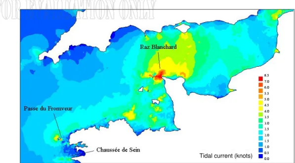
Only a fraction of the global ocean energy resource is to be found in sites which are economically feasible to explore with available technology. However, this fraction could still make a considerable contribution to electricity supply. This is the reason why the marine renewable sector is currently the focus of much industrial and academic research around the world [1]. Sites with attractive wave climate and intense tidal currents are abundant in the vicinity of the European coastline. It has been shown that 48% of the European tidal resource is in the UK, 42% in France, and 8% in Ireland. Three examples in France are shown in Fig. 1. The Raz Blanchard situated in Cap de la Hague experiences extreme tidal currents exceeding 8 knots and leading to a large amount of kinetic energy flux.
There are basically two ways of generating electricity from marine and tidal currents: by building a tidal barrage across an estuary or a bay in high tide areas, or by extracting energy from free flowing water (tidal kinetic energy). Within the last few decades, developers have shifted towards technologies that capture tidally-driven coastal currents or tidal stream [2]. The astronomic nature of this resource makes it predictable, to within 98% accuracy for decades, and independent of prevailing weather conditions. This predictability is critical to a successful integration of renewable energy in the electrical grid [3].
In this context, it is obvious that there is a need to quantify the potential to generating electricity from these various sites [4]. This paper deals then with the modeling and the control of a variable speed DFIG-based marine current turbine with and without tidal current speed sensor. The proposed MPPT control strategy is tested using tidal current data from the Raz de Sein (Brittany, France) for a 7.5-kW prototype over various flow regimes. It should be noted that when scanning the literature, one will find very few papers in this topic [5].
II.MARINE CURRENT TURBINE MODELING
The global scheme for a grid-connected marine current turbine is given by Fig. 2. A. The Resource Model
1) Resource Potential. The total kinetic power in a marine current turbine has a similar dependence to that of a wind turbine and is governed by the following equation [6-7].
3
1
2 tide
Tidal current (knots) Tidal current (knots)
Fig. 1. Raz Blanchard, Fromveur, and Raz de Sein sites in the French western coast.
Resource (Tidal current) Marine turbine Gearbox Generator Grid connection Resource (Tidal current) Marine turbine Gearbox Generator Grid connection Fig. 2. Marine current turbine global scheme.
However, a marine energy turbine can only harness a fraction of this power due to losses and (1) is modified as follows.
3
1
2 p tide
P C A V (2)
For marine turbines, Cp is estimated to be in the range 0.35–0.5 [8].
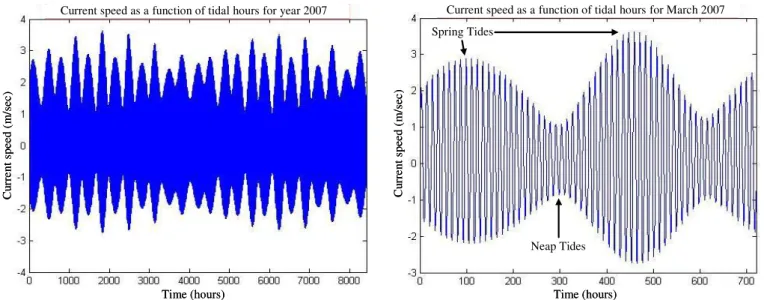
2) Resource Model. Tidal current data are given by Hydrographic and Oceanographic Services as for example the French Navy Hydrographic and Oceanographic Service (SHOM) and is available for various locations in chart form. The available charts give, for a specific site, the current velocities for spring and neap tides. These values are given at hourly intervals starting at 6 hours before high waters and ending 6 hours after. Therefore, knowing tides coefficient, it is easy to derive by interpolation a simple and
45
95 45 st nt tide nt C V V V V (3)Where C is the tide coefficient which characterize each tidal cycle (95 and 45 are respectively the spring and neap tide medium coefficient). This coefficient is determined by astronomic calculation of earth and
moon positions. Vst and Vnt are respectively the spring and neap tide current velocities for hourly intervals
starting at 6 hours before high waters and ending 6 hours after. For example, 3 hours after the high tide in
Brest, Vst = 1.8 knots and Vnt = 0.9 knots. Therefore, for a tide coefficient C = 80, Vtide = 1.53 knots.
This first-order model is then used to calculate the tidal velocity each hour. The implemented model will allow the user to compute tidal velocities in a predefined time range. Figure 3 shows the model output for a month (March 2007) and for a year (2007). This adopted resource model has several advantages including its modularity not to mention its simplicity. Indeed, the marine turbine site can be changed, the useful current velocity can be adapted, and the time range taken into account can also be adapted from one month to one year.
B. The Turbine Rotor Model
The harnessing of the energy in a tidal flow requires the conversion of kinetic energy in a moving fluid, in this case water, into the motion of a mechanical system, which can then drive a generator. It is not too surprising, therefore, that many developers suggest using technology that mirrors that which has been successfully utilized to harness the wind, which is also a moving fluid [2]. Moreover, much of the technology is based upon the use of horizontal axis turbines.
Time (hours) C ur re nt sp ee d (m /s ec )
Current speed as a function of tidal hours for year 2007
Time (hours) C ur re nt sp ee d (m /s ec )
Current speed as a function of tidal hours for year 2007
Time (hours) C ur re nt sp ee d (m /s ec )
Current speed as a function of tidal hours for March 2007 Spring Tides Neap Tides Time (hours) C ur re nt sp ee d (m /s ec )
Current speed as a function of tidal hours for March 2007 Spring Tides
Neap Tides
Compared to the largest wind turbines operating today, the output power and the size of a classical tidal turbine are extremely promising. Indeed, this is due to the sea water huge density and to the current velocity. For illustration, Fig. 4 shows a tidal turbine against an offshore wind turbine of the same power rating. Therefore, much can be transferred from the modeling and operation of wind turbines [9]. There are, however, a number of fundamental differences in the design and operation of marine turbines. Particular differences entail changes in force loadings, immersion depth, different stall characteristics, and the possible occurrence of cavitation [10-11].
Turbine rotor aerodynamics refers to the interaction of the wind turbine rotor with the incoming wind. The treatment of rotor aerodynamics in all current design codes is based on Glauert well-known, and well established BEM theory [12]. The BEM method has therefore been used for the marine turbine rotor modeling. It allows an iterative calculation of drag and lift coefficient for each blade section and the calculation of the global performance of a turbine. Indeed, it is widely used in the industry as a computational tool to predict aerodynamic loads and power of turbine rotors. Details of the model adaptation to marine turbines are given in the authors’ previous work [13]. For a given turbine geometry (number of blades, geometry of the blades, pitch, etc.), this model allows to calculate the mechanical power and torque for each fluid speed and turbine rotational speed. This model is relatively simple and computationally fast meeting the requirements of accuracy and control loop computational speed. Examples of the obtained results are given in section IV.A.
C. The Generator Model
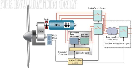
The generator chosen for the marine current system was the DFIG [14]. DFIG-based marine turbines, as for wind turbines, will offer several advantages including variable speed operation, and four-quadrant active and reactive power capabilities. Such system also results in lower converter costs and lower power losses compared to a system based on a fully fed synchronous generator with full-rated converter. Moreover, the generator is robust and requires little maintenance [5], [15-18]. A schematic diagram of a DFIG-based generation system is shown in Fig. 5.
The control system is usually defined in the synchronous d-q frame fixed to either the stator voltage or the stator flux [14]. For the proposed control strategy, the generator dynamic model written in a synchronously rotating frame d-q is given by (4).
3 ( ) 2 sd sd s sd s sq sq sq s sq s sd rd rd r rd r rq rq qr r rq r rd sd s sd rd sq s sq rq rd r rd sd rq r rq sq em sq rd sd rq em m d V R I dt d V R I dt d V R I dt d V R I dt L I M I L I M I L I M I L I M I T pM I I I I d J T T f dt (4)
III.CONTROL OF THE DFIG-BASED MARINE CURRENT TURBINE
The DFIG stator-side reactive power is given by
3 2
s sq sd sd sq
Q V I V I (5)
For a decoupled control, a d-q reference frame attached to the stator flux was used. Therefore, assuming the per phase stator resistance negligible and setting the stator flux vector aligned with the d-axis, the reactive power can be expressed as [14]
Gear Pitch Drive Brake DFIG DFIG Frequency Converter Marine Turbine Control
Main Circuit Breaker
Medium Voltage Switchgear Line Coupling Transformer Gear Pitch Drive Brake DFIG DFIG Frequency Converter Marine Turbine Control
Main Circuit Breaker
Medium Voltage Switchgear Line Coupling
Transformer
Fig. 5. Schematic diagram of a DFIG-based generation system.
3 2 s s s rd s V Q M I L (6)Since the DFIG control objective is to generate the maximum power, the speed reference is given by an MPPT strategy while setting the reactive power to zero [19]. Therefore, the reference of the rotational speed control loop is adjusted so that the turbine will operate around the maximum power for the current tidal speed. In order to determine whether this reference must be either increased or decreased, it is
necessary to estimate the operating point current position regarding the PMCT() curves maximum (Fig. 6).
As the rotor turbine model is well-known [13], the optimal value of the tip speed ratio λopt, and Pmax =
P(λopt) can be easily deduced. Therefore, the MCT will operate at the optimal operating point if
( )t opt
(7)
which supposes that the shaft rotational speed is closed-loop controlled so as to reach its optimal value
( ) opt ( )
ref t Vtide t
R
(8)
Here R is the marine turbine rotor radius.
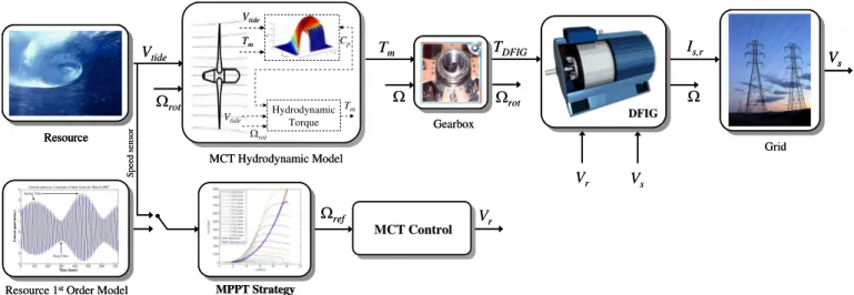
The above proposed control strategy of the DFIG-based MCT is illustrated by the block diagram in Fig. 7.
Po w er (W ) (rad/sec) Po w er (W ) (rad/sec)
Fig. 6. Power curves for different tidal current speed.
MCT Hydrodynamic Model
Resource 1stOrder Model
Time (hours) C ur re nt sp ee d (m /s ec )
Current speed as a function of tidal hours for March 2007 Spring Tides Neap Tides Time (hours) C ur re nt sp ee d (m /s ec )
Current speed as a function of tidal hours for March 2007 Spring Tides Neap Tides MPPT MPPT StrategyStrategy Tm Vtide ref Resource Vtides Cp Vtides Cp Hydrodynamic Torque Cp Vtide Vtide rot Tm Tm DFIG DFIG TDFIG Is,r Gearbox Grid Vs Vr Vr Vs rot rot MCT Control MCT Control Sp ee d se ns or MCT Hydrodynamic Model
Resource 1stOrder Model
Time (hours) C ur re nt sp ee d (m /s ec )
Current speed as a function of tidal hours for March 2007 Spring Tides Neap Tides Time (hours) C ur re nt sp ee d (m /s ec )
Current speed as a function of tidal hours for March 2007 Spring Tides Neap Tides Time (hours) C ur re nt sp ee d (m /s ec )
Current speed as a function of tidal hours for March 2007 Spring Tides Neap Tides Time (hours) C ur re nt sp ee d (m /s ec )
Current speed as a function of tidal hours for March 2007 Spring Tides Neap Tides MPPT MPPT StrategyStrategy Tm Vtide ref Resource Resource Resource Vtides Cp Vtides Cp Hydrodynamic Torque Cp Vtide Vtide Vtide rot Tm Tm Tm DFIG DFIG DFIG DFIG TDFIG Is,r Gearbox Grid Vs Vs Vr Vr Vs rot rot MCT Control MCT Control Sp ee d se ns or
Fig. 7. The proposed control structure.
IV.VALIDATION RESULTS
A. Validation Data and Parameters
In this work, the Raz de Sein site was chosen above several others listed in the European Commission report EUR16683 [20] due to the presence of high speed current coupled with appropriate depths suitable for marine turbine. Moreover, the marine current speed distribution for most of the time is greater than the minimum, estimated to be 1 m/sec, required for economic deployment of marine current turbine [4].
The turbine rotor model was validated through the comparison of the simulation model with experimental data from the available literature [13], [21]. Indeed, the simulated marine turbine
corresponds to the one tested in [21] (Fig. 8). The obtained power coefficient Cp is shown in Fig. 9: For a
0.8 m model of an MCT, a current velocity Vtide = 1.5 m/sec, and a pitch angle = 25°; a Cp of about 0.32
was found in comparison to 0.36 in the tank test. The adopted marine current turbine is of 1.44 m diameter and 7.5-kW.
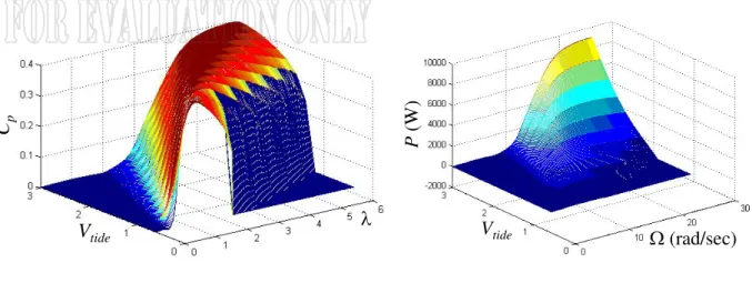
For the given turbine geometry the power for each rotor speed and a tidal current speed is determined
by the BEM hydrodynamic model. In this context, the obtained power coefficient Cp and the extractable
power curves are shown in Fig. 10.
The 7.5-kW DFIG parameters are given in the appendix.
Fig. 8. The tested marine current turbine [13].
Cp Cp Comparison Cp Comparison Cp Cp Cp Comparison Cp Comparison Cp (a) (b)
Vtide Cp Vtide Cp Vtide P (W ) (rad/sec) Vtide P (W ) (rad/sec)
(a) Cp(λ,Vtide) curves. (b) The extractable power P(,Vtide).
Fig. 10. Performances of the studied marine current turbine. B. Validation Results for a Filtered Resource
In this first case, the marine current turbine is simulated considering a resource first-order model (3). The resource is assumed to be non disturbed by sea-surface effects and by other turbulences (filtered resource).
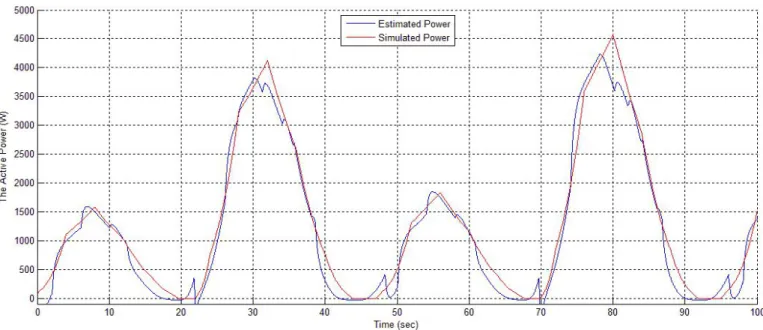
The DFIG-based MCT control performances are shown in Figs. 11 and 12 respectively illustrating the rotor speed tracking performance and the generated active power. The main merit of the DFIG is its capability to deliver constant voltage and frequency output for ±30% speed variation around conventional synchronous speed for a reduced power rotor AC/AC converter. Therefore, the rotor speed reference generated by the MPPT strategy was limited at ±30% of the conventional synchronous speed.
The obtained results show good tracking performances of the DFIG rotor speed. However, the active power exhibits some tracking errors.
The main difficulty to set the MCT multiphysic model was to include a variety of sub-models with different timescale such as the hydrodynamic loads, the turbine, the generator, etc. The built MCT model includes all the dynamic effects from very fast effects to very slow hydrodynamic loads. In our case and for efficient analysis, the tidal velocity timescale was changed from hours to seconds (a period of 24-h is represented by 100-sec). It should be noticed that the DFIG dynamic response is still faster than the hydrodynamic loads and the generated power is not affected by this change.
Fig. 11. The DFIG rotor speed and its reference.
Fig. 12. The DFIG active power. C. Validation Results for a Turbulent Resource
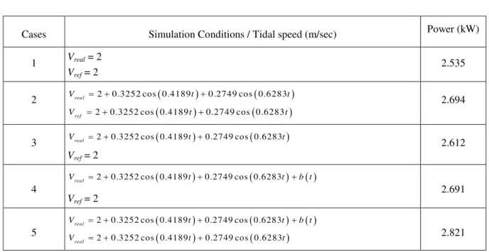
To evaluate the resource model and its impact on the generated power, three types of resources taking into account external disturbance have been simulated in different cases summarized in Table 1. In the considered cases, simulations are carried out during 90 sec. This simulation time has been chosen to evaluate the influence of swell and sea surface effect disturbances which have time constants or periods of few seconds. In these conditions, the predicted average value of the tidal speed (3) is assumed to be constant and equal to 2 m/sec (4 knots). It should be noted that the carried out simulations will also allow the evaluation of the predictability degree of the kinetic energy.
Table 1. The simulated cases.
Cases Simulation Conditions / Tidal speed (m/sec) Power (kW)
1 Vreal = 2 Vref = 2
2.535 2 Vreal 2 0.3252 cos 0.4189 t0.2749 cos 0.6283 t
2 0.3252 cos 0.4189 0.2749 cos 0.6283
ref
V t t 2.694
3 Vreal 2 0.3252 cos 0.4189 t0.2749 cos 0.6283 t
Vref = 2 2.612 4 2 0.3252 cos 0.4189 0.2749 cos 0.6283 real V t t b t Vref = 2 2.691 5 2 0.3252 cos 0.4189 0.2749 cos 0.6283 real V t t b t 2 0.3252 cos 0.4189 0.2749 cos 0.6283 real V t t 2.821
In the simulated cases, we consider several waveform cases for the tidal speed (Vreal) with and without
disturbances. The three taken resource values are composed by the kinetic speed, the swell disturbance,
and a random signal b(t) that represents all the other disturbances. Several tidal speed references (Vref)
taken as a reference for the control block (MPPT) are considered. In particular, the DFIG-based MCT performances are evaluated when a perturbed resource is associated to a constant reference tidal speed (cases 1, 3, and 4). These cases allow the use of the tidal predicted average speed as a reference for the MPPT calculations and therefore allow the DFIG-based MCT control without a tidal speed sensor.
To take into account the swell effect, which is considered as the most disturbing one for our resource model, a Stokes model have been used. This model is a very classical first order model used to predict the swell influence in the sea water column. For given swell amplitude H, a period T, a swell length L and ground sea depth d as shown in Fig. 13, the speed potential can be calculated for each depth z. The water speed created by the swell effect can be deduced by spatial derivation of this potential [22].
2 sin 2 2 2 tides V grad z d ch H L L t x d T T L sh L (9)
T : Swell period L : Swell length H : Swell amplitude d : Sea depth T : Swell period L : Swell length H : Swell amplitude d : Sea depth
Fig. 13. Swell characteristics.
This speed disturbance, calculated for typical intense swell specifications, is added to the predicted tidal current speed to roughly estimate how the swell can disturb the tidal current values in the turbine disk (case 2 to 5). It is also possible to add a white noise b(t) to the tidal current value which allows taking into account turbulence phenomena (case 4 and 5).
Figure 14 shows the DFIG rotor speeds and the corresponding generated active powers for Table 1 cases. It should be noted that Table 1 also gives the predicted active power for the different cases. The obtained results prove that the adopted first order model that predicts the resource tidal speed is quite efficient as a reference for the MPPT control block and can provide up to 95% -power ratio between cases 4 and 5 in Table 1- of the extractable power (in average) even if the resource is heavily disturbed. It can be noticed that if the real tidal current speed is used as a reference for the MPPT (cases 2 and 5); it leads to high variations of DFIG-based MCT speed and power that will mechanically stress the MCT. However, if the predicted average speed is used as a reference (cases 1, 3 and 4) these phenomena are strongly reduced without significantly affecting the MCT global extracted power.
This leads to the conclusion that a control strategy using the predicted tidal current average speed for the MPPT will not overload the marine current turbine even with a heavily perturbed resource.
Time (sec) T he D FI G ro to r s pe ed ( ra d/ se c) Time (sec) T he D FI G a ct iv e po w er (k W ) Time (sec) T he D FI G a ct iv e po w er (k W )
Time (sec) T he D FI G ro to r s pe ed ( ra d/ se c) Time (sec) T he D FI G a ct iv e po w er (k W ) (b) Case 1 and 4.
Time (sec) T he D FI G ro to r s pe ed ( ra d/ se c) Time (sec) T he D FI G a ct iv e po w er (k W ) (c) Case 1 and 5.
Time (sec) T he D FI G ro to r s pe ed ( ra d/ se c) Time (sec) T he D FI G a ct iv e po w er (k W ) (d) Case 4 and 5.
V.CONCLUSIONS
This paper dealt with the modeling and the control of a variable speed doubly-fed induction generator based marine current turbine. An MPPT-based control strategy was proposed for variable speed control. It relies on the resource and the marine turbine models that were validated by experimental data. Tidal current data from the Raz de Sein (Brittany, France) have been used to run simulations of a 7.5-kW prototype over various flow regimes. Simulation results show that the proposed control strategy is effective in terms of speed tracking. However, the active power exhibits some tracking errors of a maximum of 10%. These results prove the need for direct active power control.
Moreover, the sensitivity of the proposed control strategy was analyzed regarding a disturbed resource including the swell effect as it is considered as the most disturbing one.
The obtained results are very encouraging. Indeed, they prove that the adopted first order model that predicts the resource tidal speed is quite efficient as a reference for the MPPT control block and can provide up to 95% of the extractable power even if the resource is heavily disturbed. Furthermore, simulation results also show that a control without a tidal current speed sensor can be used for a marine current turbine system thanks to the predictability of the resource.
APPENDIX
PARAMETERS OF THE USED DFIG
Rs = 0.455 Ω, Ls = 0.084 H, Rr = 0.62 Ω, Lr = 0.081 H, M = 0.078 H, J = 0.3125 kg.m2, f = 6.73 10-3 Nms-1
REFERENCES
[1] C.M. Johnstone, K. Nielsen, T. Lewis, A. Sarmento and G. Lemonis, “EC FPVI co-ordinated action on ocean energy: A European platform for sharing technical information and research outcomes in wave and tidal energy systems,” Renewable Energy, vol. 31, pp. 191-196, 2006.
[2] S.E. Ben Elghali, M.E.H. Benbouzid and J.F. Charpentier, “Marine tidal current electric power generation technology: State of the art and current status,” in Proceedings of IEEE IEMDC'07, Antalya (Turkey), vol. 2, pp. 1407-1412, May 2007.
[3] 2005 IEEE Power Engineering Society General Meeting Panel Session, “Harnessing the untapped energy potential of the oceans: Tidal, wave, currents and OTEC,” San Francisco (USA), June 2005. [4] L.E. Myers and A.S. Bahaj, “Simulated electrical power potential harnessed by marine current
turbine arrays in the Alderney Race,” Renewable Energy, vol. 30, p. 1713-1731, 2005.
[5] J.W. Park, K.W. Lee and H.J. Lee, “Wide speed operation of a doubly-fed induction generator for
tidal current energy,” in Proceedings of the IEEE IECON'2004, Busan (South Korea), vol. 2, pp.
1333-1338, 2004.
[6] J.S. Couch and I. Bryden, “Tidal current energy extraction: Hydrodynamic resource characteristics,” Proc. IMechE, Part M: Journal of Engineering for the Maritime, vol. 220, n°4, pp. 185-194, 2006. [7] A.S. Bahaj and L.E. Myers, “Fundamentals applicable to the utilisation of marine current turbines for
energy production,” Renewable Energy, vol. 28, pp. 2205-2211, 2003.
[8] L.E. Myers and A.S. Bahaj, “Power output performance characteristics of a horizontal axis marine
current turbine,” Renewable Energy, vol. 31, pp. 197-208, 2006.
[9] E. Bossanyi, Wind Energy Handbook. New York: Wiley, 2000.
[10] W.M.J. Batten, A.S. Bahaj, A.F. Molland and J.R. Chaplin, “Experimentally validated numerical method for the hydrodynamic design of horizontal axis tidal turbines,” Ocean Engineering, vol. 34, n°7, pp. 1013-1020, May 2007.
[11] W.M.J. Batten, A.S. Bahaj, A.F. Molland and J.R. Chaplin, “Hydrodynamics of marine current
turbines,” Renewable Energy, vol. 31, pp. 249-256, 2006.
[12] H. Glauert, The Elements of Airfoil and Airscrew Theory. Cambridge University Press (2nd Ed.):
1959.
[13] S.E. Ben Elghali, R. Balme, K. Le Saux, M.E.H. Benbouzid, J.F. Charpentier and F. Hauville, “A simulation model for the evaluation of the electrical power potential harnessed by a marine current turbine,” IEEE Journal on Oceanic Engineering, vol. 32, n°4, pp. 786-797, October 2007.
[14] S. Müller, M. Deicke and R.W. De Doncker, “Doubly fed induction generator systems,” IEEE Industry Applications Magazine, vol. 8, n°3, pp. 26-33, May-June 2002.
[15] J.M. Carrasco, L.G. Franquelo, J.T. Bialasiewicz, E. Galvan, R.C.P. Guisado, M.A.M. Prats, J.I. Leon and N. Moreno-Alfonso, “Power-electronic systems for the grid integration of renewable energy sources: A survey,” IEEE Trans. Industrial Electronics, vol. 53, n°4, pp. 1002-1016, June 2006. [16] G. Tapia, A. Tapia and X. Ostolaza, “Proportional–integral regulator-based approach to wind farm
reactive power management for secondary voltage control,” IEEE Trans. Energy Conversion, vol. 22, n°2, pp. 488-498, June 2007.
[17] T.K.A. Brekken and N. Mohan, “Control of a doubly fed induction wind generator under unbalanced grid voltage conditions,” IEEE Trans. Energy Conversion, vol. 22, n°1, pp. 129-135, March 2007. [18] A. Tapia, G. Tapia, X. Ostolaza and J.R. Saenz, “Modeling and control of a wind turbine driven
doubly fed induction generator,” IEEE Trans. Energy Conversion, vol. 18, n°2, pp. 194-204, June 2003.
[19] E. Koutroulis and K. Kalaitzakis, “Design of a maximum power tracking system for wind-energy-conversion applications,” IEEE Trans. Industrial Electronics, vol. 53, n°2, pp. 486-494, April 2006. [20] EU Commission, “The exploitation of tidal marine currents,” Report EUR16683EN, 1996.
[21] A.S. Bahaj, A.F. Molland, J.R. Chaplin and W.M.J. Batten, “Power and thrust measurements of marine current turbines under various hydrodynamic flow conditions in a cavitation tunnel and a towing tank,” Renewable Energy, vol. 32, pp. 407-426, 2007.
[22] The Wise Group, “Wave modelling – The state of the art,” Progress in Oceanography, vol. 75, n°4, pp. 603-674, December 2007.
Seif Eddine Ben Elghali (S’04) was born in Téboulba, Tunisia, in 1981. He received the B.Sc. degree in Electrical Engineering in 2005 from ENIT, Tunis, Tunisia, and the M.Sc. degree also in Automatic Control in 2006 from the University of Poitiers, Poitiers, France.
He is currently pursuing Ph.D. studies on marine tidal turbine modeling and control. Mohamed El Hachemi Benbouzid (S’92–M’95–SM’98) was born in Batna, Algeria, in 1968. He received the B.Sc. degree in electrical engineering from the University of Batna, Batna, Algeria, in 1990, the M.Sc. and Ph.D. degrees in electrical and computer engineering from the National Polytechnic Institute of Grenoble, Grenoble, France, in 1991 and 1994, respectively, and the Habilitation à Diriger des Recherches degree from the University of Picardie “Jules Verne,” Amiens, France, in 2000.
After receiving the Ph.D. degree, he joined the Professional Institute of Amiens, University of Picardie “Jules Verne,” where he was an Associate Professor of electrical and computer engineering. In September 2004, he joined the University Institute of Technology (IUT) of Brest, University of Brest, Brest, France, as a Professor of electrical engineering. His main research interests and experience include analysis, design, and control of electric machines, variable-speed drives for traction and propulsion applications, and fault diagnosis of electric machines.
Prof. Benbouzid is a Senior Member of the IEEE Power Engineering, Industrial Electronics, Industry Applications, Power Electronics, and Vehicular Technology Societies. He is an Associate Editor of the
IEEE TRANSACTIONS ON ENERGY CONVERSION, the IEEE TRANSACTIONS ON INDUSTRIAL ELECTRONICS,
the IEEE TRANSACTIONS ON VEHICULAR TECHNOLOGY, and the IEEE/ASME TRANSACTIONS ON
MECHATRONICS.
Jean Frédéric Charpentier (M'02) was born in Tananarive, Madagascar, in 1969. He received the M.Sc. and PhD degree in electrical engineering from the National Polytechnic Institute of Toulouse, Toulouse, France in 1993 and 1996 respectively.
From 1996 to 1997 he was a post doctoral fellow at Laval University, Québec, Canada. From 1997 to 2002 he was an Assistant Professor at the University Institute of Technology (IUT) of Brest, University of Brest, Brest, France. Since 2002, he has been an Associate Professor in the French Naval Academy in Brest, France. His current research interests include design aspects on electrical machines and drives, electrical naval propulsion systems and marine renewable energy.
![Fig. 4. Tidal turbine against an offshore wind turbine [© MCT].](https://thumb-eu.123doks.com/thumbv2/123doknet/7305764.209518/7.892.314.600.695.1037/fig-tidal-turbine-offshore-wind-turbine-mct.webp)
![Fig. 8. The tested marine current turbine [13].](https://thumb-eu.123doks.com/thumbv2/123doknet/7305764.209518/11.892.299.613.388.620/fig-tested-marine-current-turbine.webp)