Science Arts & Métiers (SAM)
is an open access repository that collects the work of Arts et Métiers Institute of
Technology researchers and makes it freely available over the web where possible.
This is an author-deposited version published in: https://sam.ensam.eu Handle ID: .http://hdl.handle.net/10985/8765
To cite this version :
Anthony ROUX, Jennyfer LECOMPTE, Laure-Lise GRAS, Sébastien LAPORTE, Ivan
IORDANOFF - Tensile response of the muscle-tendon complex using discrete element model - In: Societe de Biomécanique, France, 2014-08-27 - Computer Methods in Biomechanics and
Biomedical Engineering, Supplement 1 - 2014
Any correspondence concerning this service should be sent to the repository Administrator : archiveouverte@ensam.eu
*Corresponding author. Email: anthony.roux@ensam.eu
Tensile response of the muscle-tendon complex
using Discrete Element Model
A. Roux*†, J. Lecompte†, L-L. Gras†, S. Laporte†, I. Iordanoff
‡ † Arts et Métiers ParisTech. LBM. 151 bd de l’hôpital. 75013 Paris‡ Arts et Métiers ParisTech. I2M. Esplanade des Arts et Métiers. 33405 Talence
Keywords: Muscle-tendon complex, Discrete Element Method, pennation angle, hyper-elastic behavior
1.
Introduction
Tear of the muscle-tendon complex (MTC) is one of the main causes of sport injuries (De Labareyre et al. 2005). However, the mechanisms leading to such injury are still unclear (Uchiyama et al. 2011). Before modeling the tear of the MTC, its behavior in tensile test will be first studied. The MTC is a multi-scale, non isotropic and non continuous structure that is composed of numerous fascicles gathered together in a conjunctive sheath (epimysium). Many MTC models use the Finite Element Method (FEM) (Bosboom et al. 2001) to simulate MTC’s behavior as a hyperviscoelastic material. The Discrete Element Method (DEM) used for modeling composite materials (Iliescu et al. 2010) could be adapted to fibrous materials as the MTC. Compared to FEM, the DEM could allow to capture the complex behavior of a material with a simple discretization scheme in terms of concept and implementation as well as to understand the influence of fibers’ orientation on the MTC behavior. The aim of this study was to obtain the force/displacement relationship during a numerical tensile test of a pennate muscle model with DEM.
2.
Material and Methods
Geometrical construction with DEM
The MTC model was built with the GranOO (Granular Object Oriented) software, developed at the Mechanics Institute of Bordeaux (I2M) by J.L. Charles et al. Fibers were constructed with spherical discrete elements linked by springs. The extra cellular matrix (ECM) was created by springs between fibers, in longitudinal and transversal directions. Tendons of the MTC were composed of fibers with links between them to create sliding. Those tendon’s fibers presented the same architecture as muscle’s fibers and they were composed of the same material as epimysium. The myo-tendinous junction was constructed by multi-links between tendon and muscle to respect the finger-like insertion (Turrina et al. 2013) (Figure 1).
Mechanical properties
Young’s modulus values of the MTC’s components were retrieved from the literature to model the
microscopic stiffness of each spring (Table 1). The stiffness of each element was related to discrete elements’ cross-sectional area, initial length of links and structure’s Young’s modulus. Myo-tendinous junction’s Young’s modulus was supposed to be a compromising value between Young’s moduli of muscle and tendon. ECM’s Young’s modulus was also fixed.
Table 1 : Young’s Modulus of MTC’s components
Tensile test simulation
In this numerical tensile test, the MTC was fixed on its lower extremity and the upper extremity was subjected to a linear displacement. The force/displacement relationship was computed during the numerical test. Pennation angle variation and volume of the MTC was also computed to confirm the incompressibility property of the MTC.
Figure 1: MTC geometry in DEM
3.
Results and Discussion
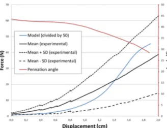
The force/displacement curve could be divided into two parts. In the first part, the force was approximately null. It was due to the alignment and the orientation of all muscle’s fiber with the tensile axis which was the main axis of the MTC. The second part showed the hyper-elastic behavior of the stretching MTC, with a gap of 2N in order to fit with in vitro experimental data of Gras et al. (2012) over the sternocleidomastoideus muscle (SCM) (Figure 2). MTC architectural parameters are computed regarding in vitro SCM data from Gras et al. (2012), except for pennation angle which has been arbitrary chosen at 45°.
MTC Components Young's Modulus (MPa) Reference
Fiber 28,2 Lieber et al. 2003
Tendon 800 Matschke et al. 2013
ExtraCellular Matrix 100 /
Figure 2: Example of force/displacement curve (blue) and pennation-angle/displacement curve (red) for a MTC with muscle’s length = 134 mm, tendon's length = 20.1 mm, central width = 16.1 mm and pennation angle = 45°.
The force/displacement computed curve’s shape was in agreement with experimental ones despite a 50 times higher value. This difference could be attributed to the chosen values of mechanical properties of MTC’s components, which were not adapted to our model. Values of mechanical properties should be adjusted in order to fit with experimental data. Furthermore, we used Young’s modulus from patellar tendon (Matschke et al. 2013) which could be not directly applied to SCM tendon. In addition, we have made hypothesis about mechanical properties on the ECM (one of the main components of the MTC) and the myo-tendinous junction, due to the lack of data in the literature which could lead to those differences. The variation of the pennation angle during the tensile test was in agreement with the literature since during a passive muscle stretching, the pennation angle decreased, allowing a greater alignment between fibers and the muscle axis (Zhao et al. 2011). The variation of the volume of the MTC, calculated during the simulation, was less than 1%, as previously described in the literature. This confirms the incompressibility property of MTC thanks to springs’ properties in DEM.
4.
Conclusions
The DEM seems to be a promising method to model the Muscle-Tendon Complex. The shape of numerical curve was in agreement with the experimental ones confirming the possibility to model the hyper-elastic macroscopic response of the muscle with simple elastic microscopic elements. The next step will be to adjust the numerical model in regard to the literature and to add viscoelastic properties in the MTC components. Furthermore, the study of the stress inside a cross
sectional area of muscle and tendon during the tensile test will help to detect where the MTC tear is most likely to occur.
References
Bosboom EM, Hesselink MK, Oomens CW, Bouten CV, Drost MR, Baaijens FP. 2001 Passive transverse mechanical properties of skeletal muscle under in vivo compression. J. Biomech. 34(10):1365–1368.
De Labareyre H, Rodineau J, Brasseur JL, Roger B, Bouvat E. 2005 Critères de reprise après un accident musculaire. J. Traumatol. Sport 22:232-235.
Gras LL, Mitton D, Viot P, Laporte S. 2012 Hyper-elastic properties of the human
sternocleidomastoideus muscle in tension. J. Mech. Behav. Biomed. Mater. 15:131-140. Iliescu D, Gehin D, Iordanoff I, Girot F, Gutierrez
M. 2010 A discrete element method for the simulation of CFRP cutting. Compos. Sci. Technol. 70:73–80.
Lieber RL, Runesson E, Einarsson F, Friden J. 2003 Inferior mechanical properties of spastic muscle bundles due to hypertrophic but compromised extracellular matrix material. Muscle Nerve 28:464–471.
Matschke V, Jones JG, Lemmey AB, Maddison PJ, Thom JM. 2013 Patellar Tendon Properties and Lower Limb Function in Rheumatoid Arthritis and Ankylosing Spondylitis versus Healthy Controls: A Cross-Sectional Study. Sci. World J. 2013:514743.
Turrina A, Martinez-Gonzalez MA, Stecco C. 2013 The muscular force transmission system: Role of the intramuscular connective tissue. J. Bodyw. Mov. Ther. 17:95-102.
Uchiyama Y, Miyazaki S, Tarnaki T, Shimpuku E, Handa A, Omi H, Mochida J. 2011 Clinical results of a surgical technique using endobuttons for complete tendon tear of pectoralis major muscle: report of five cases. Sports Med. Arthroscopy Rehabil. Ther. Technol. 3:20.
Zhao H, Wu Y, Hwang M, Ren Y, Gao F, Gaebler-Spira D, Zhang L. 2011. Changes of calf-tendon biomechanical properties induced by passive-stretching and active-movement training in children with cerebral palsy. J. Appl. Physiol. 111:435–442.