Technology researchers and makes it freely available over the web where possible.
This is an author-deposited version published in: https://sam.ensam.eu
Handle ID: .http://hdl.handle.net/10985/7534
To cite this version :
Brahim TLILI, Corinne NOUVEAU, Yacine BENLATRECHE, Nasri MUSTAPHA, Michel LAMBERTIN - Hardness and scratch response of PVD multilayer coatings - In: 3ème Congrès International Conception et Modélisation des Systèmes Mécaniques, Tunisia, 2009-03 - CMSM 2009 - 2009
Hardness and scratch response of PVD multilayer coatings
Brahim TLILI
a, Corinne NOUVEAU
b, Yacine BENLATRECHE
b, Nasri MUSTAPHA
a,
Michel LAMBERTIN
baUR. Mécanique Appliquée, Ingénierie et Industrialisation (M.A2I), ENIT, BP 37 Le Belvédère, 1002 Tunis, Tunisie / Phone. +216 71875726 / Fax. +216 71872729,
[email protected]
,
[email protected]
bLaboratoire Bourguignon des Matériaux et Procédés (LaboMaP), Arts et Métiers ParisTech de Cluny, Rue Porte de Paris, F-71250, Cluny, France / Phone. + 33 3 85 59 53 89 / Fax. + 33 3 85 59 53 70
[email protected], [email protected],[email protected]
Abstract – In the present investigation, novel Cr/CrN, CrN/CrAlN and Cr/CrN/CrAlN multilayered coatings
thin films have been developed by dual RF magnetron sputtering. They consist of superposing Cr, CrN and CrAlN layers of 50–500nm thick, up to a total thickness of 0.45–1µm. These coatings were grown on AISI4140 steel samples. The mechanical properties of these coatings were studied by scratch-tests and nano-indentation measurements. The hardness of the films reaches 15.8 GPa for a Cr/CrN multilayered coating sputtered at a bias voltage of -900V. High peak load tests were used to estimate the film adhesion on steel substrates; critical loads (Lc2) of 11N showed weak adhesion properties of the film. Moreover, an inventory of the major scratch-tests
failure modes was established, which were classified into plastic deformation and different forms of cracking, spallation and coating perforation events. No evidence of interfacial failure(s) of the sub-layers was observed after the adhesion and nanoindentation tests.
Keywords: Adhesion / multilayer / nanoindentation / scratch-tests / PVD.
Résumé – Lors de la présente étude, de nouveaux revêtements minces multicouches Cr/CrN, CrN/CrAlN et
Cr/CrN/CrAlN ont été développés par pulvérisation RF dual magnétron. Ils se composent en une superposition de couches de Cr, CrN et CrAlN de 50-500nm d'épaisseur individuelle, jusqu'à une épaisseur totale de 0,45-1μm. Ces revêtements ont été déposés sur des échantillons en acier AISI4140. Les propriétés mécaniques de ces revêtements ont été étudiées par scratch-tests et des mesures de nano-indentation. La dureté des films atteint 15,8 GPa pour le revêtement multicouche Cr/CrN déposé sous une tension de -900V appliquée à la cible de chrome. Des tests sous une charge normale élevée de 20N ont été utilisés pour estimer l'adhérence de film avec le substrat de base. Une charge critique (Lc2) de 11N montre une bonne adhérence du film avec l’acier. En outre, un
inventaire des différents types d’endommagements obtenus par scratch tests a été fait. Ceux-ci ont été classés selon la présence de déformation plastique et des différentes formes de fissuration. Aucune délamination inter- faciale des sous-couches n’a été observée après les tests d’adhérence et de dureté.
1 Introduction
Among many ways to enhance the mechanical properties of hard coatings, one is to deposit multilayer structures. A simple way is to produce metal/metal nitride multilayers. Unlike other multilayer systems (e.g.TiN/NbN) just one target is needed and the film sequence is dictated only by switching the reactive gas inlet. The first step in this regard is an interlayer of metal between the steel substrate and the hard coating, which is widely used to enhance adhesion [1]. One of the first metal nitride/metal multilayers studied was the TiN/Ti system [2]. There are also reports on the CrN/Cr system [3, 4].
The main advantage of such a sequence is an increase of fracture toughness while retaining the hardness. The soft (metallic) layers act as barriers for crack propagation [2]. Another advantage is the relief of internal stress, which enhances adhesion. For multilayers with individual layer thickness in the range of 10 nm, an increase of microhardness has been reported [3]. In this paper, several multilayer coatings were deposited with various superposed Cr, CrN and CrAlN interlayers. Two basic mechanical properties were measured (adhesion and hardness) and a comparison was done between all multilayer coatings.
2 Experimental procedure
2.1 Coating deposition
Multilayer coatings were deposited on mechanically polished steel (AISI 4140) substrates by using a dual RF magnetron sputtering system (NORDIKO type 3500-13, 56 MHz) equipped with two targets of high purity (Cr of 99.995 % and Al of 99.999 %). Before deposition the substrates were ultrasonically cleaned and, in situ, sputter etched in a pure argon atmosphere. To improve corrosion resistance and adhesion, a metallic Cr layer with a thickness of about 50 nm was deposited prior to the deposition of the ceramic CrN one. The total thickness of the coatings varies from 0.5 to 1.5 µm. The deposition conditions such as target power, bias voltage, rotational velocity of the substrate-holder and deposition time are illustrated intable 1. The deposition temperature was around 200°C.
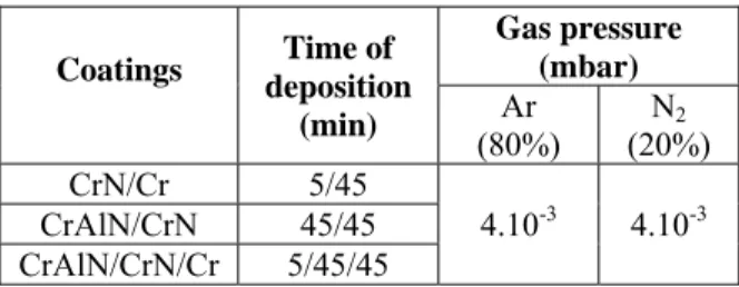
Tableau 1. Deposition conditions
Nitrogen of very high purity was introduced into the vacuum chamber as the reactive gas. The residual pressure was 10-6 mbar. The distance
between the target and surface backing was 10 cm. Previous to the deposition operation, the surface backings and targets were further etched by an argon ions bombardment during 5 min.
2.2 PVD-interlayer material
CrAlN/CrN/Cr coatings 1µm thick or CrN/Cr ones overall 0.5µm thick were deposited on AISI4140 samples using a PVD method. During the initial stage of the PVD process, a thin metallic Cr layer (≤50nm) was deposited. The CrN/Cr or CrAlN/CrN/Cr interlayers can be defined as a sort of graded coating. In fact, the bi-layer CrN/Cr or three-layer CrAlN/CrN/Cr were achieved by progressively decreasing the argon concentration inside the deposition chamber from 100% to 80% of the gas mixture, and increasing the nitrogen content. As a result, the resulting CrN or CrAlN layers are progressively poorer in nitrogen going towards the outermost layers. However, when 20% of argon is completely replaced by nitrogen in the gas mixture, a resulting layer of metallic-Cr is superimposed on the underlying graded CrN one.
2.3 Hardness measurements
The testing device is a micro-indenter Fischerscope H100 XYp (maximum load of 1 N, load resolution of 0.02 mN, depth resolution of 2 nm). Indentation consists in continuously applying a load to a specimen via a sharp Vickers pyramid indenter (angle face-to-face of 136°) and to continuously monitors the depth of penetration in the sample. The force is generated electromagnetically and incrementally increased stepwise up to the peak load of 1, 10, 100 or 1000 mN. The calibration procedure follows the requirements of standard ISO-14577.
2.4 Scratch-tests
Scratch-test is nowadays the most commonly method used to evaluate the adhesion of the coating/substrate interface. The method is repeatable and capable of generating stresses, which exceed the interfacial bond strength of thin layers.
Coatings deposition Time of (min) Gas pressure (mbar) Ar (80%) (20%) N2 CrN/Cr 5/45 4.10-3 4.10-3 CrAlN/CrN 45/45 CrAlN/CrN/Cr 5/45/45 Coatings Target power (kW) Bias voltages (V) Rotation velocity (rpm) 4 Al Cr CrN/Cr -300 -900 0.5 CrAlN/CrN CrAlN/CrN/Cr
In the scratch-test, a diamond stylus (Rockwell – tip radius 200 μm) is drawn over the sample surface under a stepwise or continuously increasing normal force (20N) until a particular failure of the coating occurs and the coating detaches. The normal load at which this happens is called the critical load Lc
expressed in Newton (N). To determine the critical load, light (LM) or scanning electron microscopy (SEM), acoustic emission (AE) and frictional force measurement are used. Coating detachment at the critical load is a quantification of the adhesion. Three critical loads (LC1, LC2 and LC3) were
determined from a set of three scratches on each specimen (Figure. 1). LC1 is the load at which
cohesive failures occurred; LC2 is the load
corresponding to first occurrence of adhesive failure (i.e., the load at which the substrate was first exposed); and LC3 is the load at which the coating
was completely removed from the scratch track. The specimen surface and diamond tip were cleaned with isopropanol before each scratch. Although acoustic emission and frictional force were recorded during the tests, the critical loads were determined by optical microscopy.
Figure 1. Worn surface micrographs of multilayer
coatings CrN/CrAlN deposited on AISI 4140 steel and tested at 20N showing critical loads LC1, LC2
and LC3.
3 Results and discussion
3.1 Hardness and elastic modulus
evaluated by nanoindentation
measurements
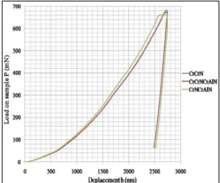
Hardness tests of the deposited multilayer coatings were made in the ‘load-unload’ mode, in which loading of the indenter with a specified force takes place, holding it for the predetermined time, and then the indenter load force is released (Figure. 2). When carrying out the test, one can observe not only plastic deformation of the material but also its elastic deformation. Microhardness determined by this way is called dynamical micro-hardness
(Figure.3). The precise meter circuit allows
registering the depth of the created imprint while loading or unloading the indenter. With the use of the Hardness Fischerscope H100 XYp, which is part of the ultramicrohardness tester, and the dependency between the load and the depth of the indenter into the examined coating, the Young’s modulus as the stiffness of coatings are summarized in table 2. The stiffness of the examined coatings is between 2.5-3N/μm, whereas Young’s modulus is between 208-260 GPa (Figure. 4).
Figure 2. Typical loading–unloading curves for
Cr/CrN, CrN/CrAlN and Cr/CrN/CrAlN multilayer coatings.
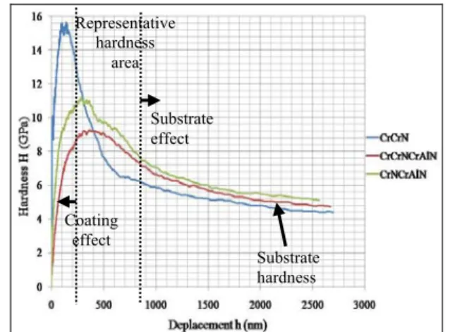
The presence of three regimes can be identified in
figure. 3. For example, for an indentation depth (d) greater than 10% of the coating thickness, the Vickers hardness value steadily decreases towards the substrate value with increasing indentation depth or equivalently increasing indentation load in the case of multilayer coatings (CrAlN/CrN). In the opposite side, for indendation depth greater than 40%, the hardness starts increasing dramatically with decreasing indentation depth or equivalently decreasing load. The results obtained here in respect of the variation of hardness with the composition of the coating are consistent with the only available data of Barshilia et al. [5] and Okumiya [6].
The Young’s modulus, also known as the modulus of elasticity (E), is difficult to determine due to the low thickness of the coatings. On the other hand, its value has a strong influence on the contact stress field, coating delamination and detachment, coating fracture, residual stress state within the coating, etc.
Figure 3. Variation of nanoindentation hardness
with indenter depth for the Cr/CrN, CrN/CrAlN and Cr/CrN/CrAlN multilayer coatings.
Figure 4. Young’s modulus of the Cr/CrN,
CrN/CrAlN and Cr/CrN/CrAlN multilayer coatings.
3.2 Adhesion evaluated by scratch-tests
How evaluate then the results of the scratch-tests? Two basically different results are normally available: on the one hand the mentioned detection of cracks and delaminations looking at the scratch by microscopy after the test procedure and on the other hand the recorded signals of tangential force (Ft) and acoustic emission (AE) during scratching.Carrying out the test in practice, the question of the definition of cracks and delaminations is still open, as is the question of the evaluation of the Ft and AE
plots. Also not clear is the correlation between the on-line plots and the aspects of damage [7].
The critical load values Lc1 of Cr/(Cr,N),
Cr/CrN/Cr(Al,N) and CrN/Cr(Al,N) multilayer coatings are 8.5, 5 and 1.3 N respectively. The adhesion value for Cr/CrN and Cr/CrN/Cr(Al, N) multilayer coatings are increased remarkably in comparison of CrN/Cr(Al, N) one. As far as Cr/ (Cr, N) coatings, the microstructures and properties of substrate and coatings have huge difference. During deformation, the stress will e concentrated
in the boundary between substrate and coatings. It results in the coating cracking and the adhesion strength decreasing. The sharp interface between the coating and the substrate may be eliminated by introducing the concept of gradient and multilayer. For CrN/Cr (Al,N) multilayer coating, interface in PVD CrN/Cr(Al,N) multilayer coating are sites for energy dissipation. The interface can then relax the stress of the coating. Moreover, the interface between Cr and CrN layers would absorbs the energy of micro cracks propagation and prevents them during coating deformation. It is possible that the direction of micro cracks propagation changes and is along the interface when the micro cracks propagate to the interface.
The values of the critical load Lc2 characterized by
adhesion of the examined multilayer coatings to the AISI4140 substrate, is caused mainly by the forces of adhesion and has been determined using the scratch-test with a linear growing load (Figure. 5-7).
Figure 5. Plot of the dependence of the acoustic
emission and friction force from the scratch path for the CrN/Cr coating deposited onto a AISI4140 substrate.
Figure 6. Plot of the dependence of the acoustic
emission and friction force from the scratch path for the CrAlN/CrN coating deposited onto a AISI4140 substrate. Substrate hardness Substrate effect Coating effect Representative hardness area
Figure 7. Plot of the dependence of the acoustic
emission and friction force from the scratch path for the CrAlN/CrN/Cr coating deposited on to a AISI4140 substrate.
The second critical load Lc2 is the point at which
the damage becomes continuous and complete delamination of the coating starts; the first appearance of cracking chipping, spallation and delamination outside or inside the track with the exposure of the material substrate – the first adhesion-related failure event. After this point, all of the acoustic emission, friction force signals become noisier [8,9]. The summary results are presented in table 2.
Employment of the additional thin (Cr) interlayer in monolayers improves adhesion of the nitride coating to the substrate, as it counteracts propagation of cracks and reduces stresses in the coating/substrate zone.
In general, the adhesion between the PVD coatings and substrate is physical adhesion because of low deposition temperature. A crack was initiated along the scratch track at a certain load, and was followed by a complete delamination leading to failure of the coating.
Tableau 2. Mechanical properties of the
multilayers.
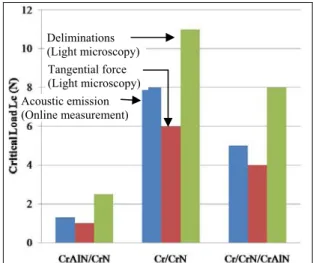
Influence of interface design. As the scratch-test is
a complex test procedure, the adhesion between coating and substrate plays a dominant role. Quantitative results are available as shown in figure 8. The results from light microscopy could be confirmed in this case by the on-line measurements of AE and Ft which is not the case in general.
Investigations on coating substrate compounds having the same covering layer CrAlN/CrN but different interfacial layers show that critical loads detected by first delaminations change in practice. Lc increases with more complex interface design.
Figure 9 illustrates the first delaminations of the multilayer coatings CrN/Cr, CrAlN/CrN and CrAlN/CrN/Cr.
Figure 8. Critical loads for different evaluation
methods over three types of interface.
On the one hand the aspects of damage can be similar, even if the critical load is different (see CrN/Cr and CrN related to CrAlN), and on the other hand the optical images show that similar values for the first delaminations, when having an identical interface (pure chromium), could be very different in size having different intermediate layer (see CrN/Cr and CrN/Cr related to CrAlN).
Coatings Thickness (µm) Lc1 (N) Lc2 (N) CrN/Cr 0.51 8.5 11 CrAlN/CrN/Cr 1 5 7.8 CrAlN/CrN 0.645 1.3 2.5 Coatings Young’s modulus (GPa) Harmonic contact stiffness, (N/µm) Hardness (GPa) CrN/Cr 260 3 15.8 CrAlN/CrN/Cr 208 2.5 9.3 CrAlN/CrN 256 2.8 11.3 Tangential force (Light microscopy) Deliminations (Light microscopy) Acoustic emission (Online measurement)
Figure 9. First delaminations for the multilayer
coatings: (A) CrN/Cr, (B) CrAlN/CrN/Cr and (C) CrAlN/CrN
4 Conclusions
Scratch testing is one of the most used techniques to evaluate adhesion of tribological hard coatings. This and the increasing demand for universal test methods that can be used in industrial applications have led to many publications in this field. Since the test procedure of the scratch-test is almost standardized, a standardized evaluation method is open for discussion [10]. One of the most interesting points is the discussion on the definition of the critical load Lc. The previous results showed
the following:
• Stress states, mechanisms of failure and aspects of damage must not be mixed in interpretation of scratch-tests.
• The optical inspection (microscopy) shows in contrast to online recording definitely the kind of damage. AE and Ft can only confirm the results
from the optical observation.
• Weak adhesion of the coatings deposited to the substrate should be connected with the existence of the interface and the difference in surface roughness from the pure metal and the PVD coatings. This may be attested by the critical load Lc2, which is in
the range 2.5-11 N, depending on the coating type. • Mechanism of the PVD coatings failure revealed by the adhesion test is connected with the arc shaped cracks caused by tension and spalling occurring at the bottom of the developing scratch. • Cr/CrN/CrAlN and Cr/CrN multilayer coatings exhibits approximately identical performance but different failure forms in scratch-tests. Nevertheless the performance of Cr/CrN/CrAlN multilayer coating in scratch-tests is superior than that of CrN/CrAlN coating due to the better adhesion of Cr/CrN multilayer coating.
• The hardness of Cr/CrN and Cr/CrN/CrAlN multilayer coatings is increased due to interface hardening. The adhesion value of Cr/CrN and Cr/CrN/CrAlN multilayer coating is better than that of CrN/CrAlN coating because the interfaces between Cr and CrN layer relax the stress during coating deformation.
5 References
[1] S. Han, J. H. Lin, X. J. Guo, S. H. Tsai, Y. O. Su, J. H. Huang, F. H. Lu, H. C. Shih, The effect of Cr interlayer on the microstructure of CrN coatings on steel, Thin Solid Films 377-378 (2000) 578-584
[2] M. Larsson, M. Bromark, P. Hedenqvist, S. Hogmark, Deposition and mechanical properties of multilayered PVD Ti---TiN coatings, Surf. & Coat. Technol. 76-77 (1995) 202-205
[3] A. Lousa, J. Romero, E. Martínez, J. Esteve, F. Montalà,L.Carreras,Multilayered
chromium/chromium nitride coatings for use in pressure die-casting, Surf. & Coat. Technol. 146-147 (2001) 268-273
[4]Riccardo Polini, Massimiliano Barletta, on the use of CrN/Cr and CrN interlayers in hot filament chemical vapour deposition (HF-CVD) of diamond films onto WC-Co substrates, Diamond & Related Materials 17 (2008) 325–335
[5] S. Baragetti, G.M. La Vecchia, A. Terranova,
Variables affecting the fatigue resistance of PVD-coated components, International Journal of Fatigue 27 (2005) 1541–1550 Introduction of crack
A
Discontinuous ductile perforation of the coatingC
Crack propagationB
[6] M. Okumiya, M. Griepentrog, Mechanical properties and tribological behavior of TiN–CrAlN and CrN–CrAlN multilayer coatings
Surf. & Coat. Technol 112 (1999) 123–128
[7] Mats Larsson, M. Bromark, Per Hedenqvist, Sture Hogmark, deposition and mechanical properties of multilayered PVD Ti-TiN coatings, Surf. & Coat. Technol 76-77 (1995) 202–205 [8] A.O. Sergici, N.X. Randall, Scratch testing of coatings, Advanced Materials and Processes 4 (2006) 1-3
[9] Y. He, I. Apachitei, J. Zhou, T. Walstock, J. Duszczyk, effect of prior plasma nitriding applied to a hot-work tool steel on the scratch-resistant properties of PACVD TiBN and TiCN coatings, Surf. & Coat. Technol 201 (2006) 2534-2539 [10] Davies, D., and J. A. Whittaker. 1967. Methods of testing the adhesion of metal coatings to metals. Metallurgical reviews, 12: 15-26