HAL Id: hal-00405314
https://hal.archives-ouvertes.fr/hal-00405314
Submitted on 20 Jul 2009
HAL is a multi-disciplinary open access
archive for the deposit and dissemination of
sci-entific research documents, whether they are
pub-lished or not. The documents may come from
teaching and research institutions in France or
abroad, or from public or private research centers.
L’archive ouverte pluridisciplinaire HAL, est
destinée au dépôt et à la diffusion de documents
scientifiques de niveau recherche, publiés ou non,
émanant des établissements d’enseignement et de
recherche français ou étrangers, des laboratoires
publics ou privés.
Global Approach for Technical Data Management
Application to Ship Equipment Part Families
Julien Le Duigou, Alain Bernard, Nicolas Perry, Jean-Charles Delplace
To cite this version:
Julien Le Duigou, Alain Bernard, Nicolas Perry, Jean-Charles Delplace. Global Approach for Technical
Data Management Application to Ship Equipment Part Families. CIRP Journal of Manufacturing
Science and Technology, Elsevier, 2009, 1 (3), pp.185-190. �10.1016/j.cirpj.2008.10.005�. �hal-00405314�
Global Approach for Technical Data Management
Application to Ship Equipment Part Families
J. Le Duigou1,2, A. Bernard1, J.C. Delplace2, S. Gabriel3
1
Institut de Recherche en Communication et Cybernétique de Nantes, Ecole Centrale de Nantes, France
2
Centre Technique de l’Industrie Mécanique, France
3
PSL Concept, France
Abstract
For several years, digital engineering has increasingly taken a more important place in the strategic issues of mechanical engineering companies. Our proposition is a global approach that enables technical data to be managed and used throughout the product life-cycle. This approach aimed to provide assistance for costing, development and the industrialization of the product, and for the capitalization, the reuse and the extension of fundamental knowledge. This approach has been experimented within a company environment that designs and produces families of ship equipment parts. This case study is presented together with the software that has been developed for this company.
Keywords:
Product Life-cycle Management, Data Model, Axiomatic Design
1 INTRODUCTION
In the present industrial context, French mechanical engineering industries are faced with growing challenges. After having refocused on their primary business in order to increase their production by increasing efficiency, they are now being asked to acquire more diversified skills. Market globalisation and an increase in customer demands has forced companies to produce more complex and individualized products in a shorter lead time. To solve this paradox (refocus on the primary business and need of multiple specific skills), companies have adapted by regrouping in order to pool their mutual skills. When this is done over a short period and on a specific project, it is called ‘virtual enterprise’, and ‘extended enterprise’ when it is done over a longer period.
One of the key points of the success of such an enterprise is the ability to communicate on the target product. Products that generate a large amount of information, i.e. the classical communication system phone/fax/email used by 90% of companies is not structured enough to enable efficient cooperation. For many years, software has been developed to pool all this information. From the EDM (Electronic Document Management) in the 80’s to the PDM (Product Data Management) and the PLM (Product Life cycle Management) nowadays, the companies and particularly the contractorsunderstand the benefit of such software.
Within this context Cetim (an industrial technical centre that represents 7000 companies of French mechanical engineering industries) decided to launch a survey on digital and collaborative engineering for the mechanical engineering companies [1]. This survey showed that only 5% of SMEs of fewer than 100 people use a PLM system to manage their technical data. However, a second survey in the same year [2] showed that more than 70% of these same SMEs consider as important the reuse of knowledge, the share of information in the company and with the outside, the security of information access and storage and the follow-up of modifications. These are the exact functionalities offered by the PLM software tools. After many visits to SMEs, the CEOs see the main obstacles to a PLM installation as being the complex
nature of the installation, use, and maintenance. It is also very costly. It seems, however, that the SMEs in the mechanical engineering industry have very specific needs in terms of PLM. 70% of these companies have customers in various business fields (mainly in the automobile and aeronautic sectors). As a consequence, they have a lot of technical skills to manage at the same time because the OEMs use different CAD and PLM systems.
There is a true need for PLM in SMEs in the mechanical engineering industry, but there are some obstacles that stand in the way of this development. Based on this premise, Cetim launched a project aimed to help the emergence of digital and collaborative engineering in those SMEs. This project links up with the strategy of the IVGI (Virtual engineering for industrial engineering) project in the IRCCyN laboratory that optimizes the integration of technical knowledge in the enterprise processes. These activities need the implementation of specific methods and data models for the mechanical engineering companies. First of all, we will work on the scientific studies that will enable us to establish the starting point of our approach. Then we will present our work method, a research/action approach, based on a spiral cycle structured on successive phases of analysis, development, experimentation, and then linking up with the methods and models modified by the experience feedback. We will describe our contribution and an industrial case study. In prospect, we target a generic method and data model to structure and manage the technical data, adapted to the SMEs in the mechanical engineering industry.
2 PLM: FROM CONCEPT TO DATA MODEL
In this chapter, we will first of all concentrate on the design of PLM, then we will examine the different methods of modelling which enable the creation of a data model on which are based the PLM functionalities. Finally we will analyse the different standards that enable the communication and sharing of technical data between companies that do not have the same data model.
2.1 The PLM concept
For many years, the software providers have been extolling the merits of PLM and the return on investment of that software. But PLM is first of all an enterprise strategy [3]. It involves managing all the data concerning a product, throughout its life-cycle, and all the internal and external actors involved in the development of this product. An acceptable definition of PLM is: “A strategic business approach that applies a consistent set of business solutions in support of the collaborative creation, management, dissemination and use of product definition information across the extended enterprise from concept to end of life - integrating people, processes, business system, and information” [4].
This concept enables, for example, planning departments to access information directly from a design department, and to propose modifications, thus shortening the product development cycle and avoiding retro design which is both long and costly. At a more strategic level, PLM enables CEOs to follow critical information on a product line or the exact time to market of new products.
Much work has been done in this field, especially in the aeronautic and automobile sectors in order to propose technical data management methods [5, 6], but also in smaller companies, such as sand foundries [7].
2.2 The modelling of business objects
PLM relies on a data model being composed of business objects that intervene in the business processes. Several modelling methods and languages have been developed so as to model these objects. The modelling languages enable these objects and related activities to be represented (SADT, IDEF3, BPMN [8], FBS-PPRE [9]]…). The establishments of patterns, based on this modelling language, describe an approach to represent the processes (CIMOSA [10], ARIS [11], GERAM [12], GRAI [13], PERA [14]…). These methods contribute to the adjustment of methods and data models required for PLM implementation.
Nevertheless, in an extended enterprise context, it is necessary for these different models to be able to communicate together. Therefore standardized models are required to enable sharing or communication between companies that have not made the same choice of modelling.
2.3 The standards of data models
Much work has been done in different sectors to increase the interoperability of data models with the standards, using mainly the STEP norm (STandards for the Exchange of Product model data) [15, 16]. STEP is an international exchange standard of ISO (ISO 10303), that describes how to represent and exchange product models by covering the whole life-cycle [17]. STEP uses a formal representation language of data called EXPRESS (ISO 10303-11), and its graphical representation, EXPRESS-G [18].
The Application Protocols (AP) are information models of STEP specific for an industry and/or a life-cycle phase. What is of interest to us is the AP214 [19], which is specific to the automobile sector, and AP239 [20] which focuses more on the aeronautic sector.
Those models are not fully interoperable, despite having common integrated resources, because the objects and the attributes are different depending on the sector of application. Hence the creation of PDM Schema [21] that tried to unify the different information models of STEP APs using their common objects.
It seems that if many methods exist for modelling business objects, their use for the creation and maintenance of a data model that supports PLM is not
detailed enough for industrial exploitation. We will keep the FBS-PPRE modelling method which enables the dynamic representation of objects independently of their roles (the same object can be a product, a resource or a process, depending on the context), which can be useful in an extended enterprise context. Moreover we notice that in spite of the existence of standards, it is still difficult to get a data model both adapted to the company and interoperable with the standards. So we will develop an approach that uses the maximum of the best appropriate standards for SMEs in the mechanical engineering industry. We will explain how we intend to obtain this result in the next chapter.
3 RESEARCH APPROACH
Our approach aims to propose a methodology in order to structure and manage the technical data of companies in the mechanical engineering industry in the context of extended enterprise. We will propose methods to structure and manage technical data and the data models needed by those methods, using the existing standards. To define these methods and to reach a common data model for the different companies, we have implemented a three-step research approach, a research/action type, based on a spiral cycle approach, typically consistent in terms of scientific experimentation: proposal of models and methods, development of the experiment, the experiment itself and results, analysis of these results and identification of the limitations of the method and the proposed models, proposition of modifications, implementation of these modifications and definition of the next experiment scenario, and so on until the desired results are obtained.
3.1 Phase 1: audit of the companies, typology of SMEs in the mechanical engineering industry and choice of pilot companies
The first phase of our work is to interview several companies to extract the present practices in terms of digital and collaborative engineering, and the best practices to implement. Benchmarking was also done on existing software tools to list the functionalities and their ability to meet SME needs.
Now we have to choose a number of pilot companies for our research.
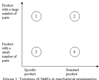
Figure 1: Typology of SMEs in mechanical engineering industry.
For this, we will make a typology of SMEs in the mechanical engineering industry. We took as differentiation axes the number of parts in the product (produced by the SME) and the fact that the product is
standard or specific. We obtained four zones (Figure 1). Thereby we deduced that there were four types of SMEs: Type1: SMEs that produce specific products with numerous parts, for example the special machine producers.
Type2: SMEs that produce standard products with numerous parts, for example the system integrators. Type3: SMEs that produce specific products with few parts, for example the mould makers.
Type4: SMEs that produce standard products with few parts, for example the elementary part producers.
This typology classifies the different companies present in an extended enterprise, from the toolmaker to the integrator, through all the intermediaries. Then we chose companies covering the different zones of our typology for our pilot companies.
3.2 Phase 2: Immersion in the companies and integration of specific methods
This consists in working in the different companies so as to directly integrate the technical data structuring and managing methods. This phase is coupled with the implementation of the methods with real data in the companies to verify the gap between our proposal and the objectives. From the initial situation of the company, we act by action/research to arrive at the final state that we defined during the audit phase.
3.3 Phase 3: Generalisation and proposal
In this last phase, based on the analysis of the different pilot companies, we will generalize the method of managing technical data, and create a global data model. This model will be compatible with the standards and applicable to all the types of companies in the mechanical engineering industry so that it may be used in an extended enterprise context.
4 A TYPE 2 COMPANY: PSL CONCEPT
This case study must enable us to put into practice methods of technical data structuring and management, adapting to this specific company. In order to do this, we will begin to analyse the needs of this company in terms of PLM. Then we will propose an approach to improve on the initial situation. And finally, we will validate this method by implementing it on a product family.
4.1 Description of the company and initial performances
The PSL Concept produces and sells equipment for ships. Among these products, there are reserve rudders, pulleys and tackles, sheaves, jam cleats and various accessories. This company organizes the main part of their products into families. In fact, as many system integrators, their products are made from standard products, to which options and modifications are added to meet customer needs.
Various processes are used to produce the parts, the blocks in carbon composite are cast, then cut by milling, and finally they are manually assembled with the other parts.
4.2 Needs in terms of PLM
After the audit done in phase 1, it seems that the main needs in this company are as follows:
Knowledge capitalisation
An improvement of design, resulting from customer feedback, a set of tests or the optimization of the designer, are not reproduced on the other products of the family without the involvement of the designer on each product. This process is lengthy and is a source of error.
BOM management
The BOM are made manually and have to be updated when there is a major modification of the product design.
Reference management
Due to the diversity of existing products (1200 references only for pulleys), the product references are hard to manage efficiently.
Quote
Giving a precise quote of a new product is complex because it is difficult to know the quantities of raw materials that will be consumed and the manufacturing time before the detailed design of the product.
Archive management
When a client comes back with a product, it is not always easy to find the original drawings of the product that has been sold with the references of the different parts. Thus the audit phase underlines the main PLM needs of this company. Now we will propose an approach to give a global solution to these needs. It is an information system based on the principles, methods and models previously presented. Then, we will implement prototype software based on our approach and we will compare the results with the objectives of the company.
4.3 Proposed approach
First of all we aimed at organizing the technical data of a family of products. The families in PSL CONCEPT could be organized by main functions of the products. It seems that an organisation of technical data by function could be the most efficient way of being able to link the design parameters and the functions of the product. With this organisation we could globally manage the technical data depending on the functions of the family.
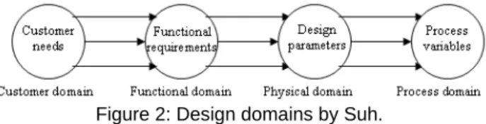
Suh [22, 23, 24] proposes the axiomatic design linking the functional parameters to the design parameters. He divides the design into four domains (customer, functional, physical, process). Each domain contains specific design objects (customer needs (CNs), functional requirements (FRs), design parameters (DPs) and process variables (PVs)) (Figure 2).
Figure 2: Design domains by Suh.
The functional requirements are defined as the minimum data that fully complete the customer needs. The design process moves on by breaking down the hierarchical upper level and zigzagging between functional, physical and process domains. To guide the designers’ choices, axioms are defined. Two design axioms have been defined as follows:
First axiom – independency axiom: maintain the independence of functional requirements.
Second axiom – information axiom: minimize the information content (of the design).
Design matrix representing the links between FRs and DPs enable the design to be visualized and optimized by applying axioms.
We were inspired by this principle to decline it into the technical data structuring and management of a family of products. We broke down the different functions of the family, then we created a set of functional dimensioning parameters for the products in order to link those parameters to the different functions (Figure 3).
4.4 Validation of the approach
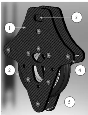
We focus on a major and well-known family of products for the company: the pulleys. We will start with a brief description of the pulleys (Figure 4).
A standard pulley is composed of two flanges (1), of one or more sheaves (2), of fastening and of different accessories as for example a jam cleat. To translate the movement, the fag end (a sailboat string) moves onto the sheave’s groove. The flanges have many options such as adding guides (4) to maintain the contact between fag end and sheave in special use conditions or beckets (5) and different kinds of openings (3) to fix the pulley.
Figure 3: Domain breakdown and links between them. Thus, if a function is not required by the customer, and if this function is only linked to a single sub-product, then this sub-product will not be present in the final product. The word sub-product is for a part in an assembly and for a part of a part. Moreover the modification of a functional parameter leads to the modification of the design parameters which are linked to it. On this basis we have developed several functionalities to meet the needs in terms of PLM of this company.
Knowledge Capitalisation
When a modification of the design is made, this modification is implemented on all the products of the family that use the function concerned by the modification. There is no longer information loss when a product is improved because if the function or the definition of the design parameter is modified, all the products of the family will be automatically modified and so have the benefit of the improvement.
Reference management
In order not to have to open a large number of references without producing the referenced product, we introduced a system of referencing based on the functions of the product family. This system enables that a new product (an unseen combination of functions) automatically obtains a reference link to the specified functions, without
having to open all the possible references beforehand. Figure 4: Description of a pulley.
Quote
A software program was implemented to automatically construct the CAD file of a pulley from the functional requirements.
After a study of the price of the product family, we noticed that the price of a product is linked to the functions of this product. So ascertaining empirically the relation between the price and each function, we were able to obtain a global price for a product from its functional definition.
To create this program we started by breaking down the functionalities of a pulley (Figure 5). Then we carried out a functional dimensioning of the different sub-parts of the pulley and we set these parameters in the CAD file. Then we brought together the dimensioning parameters in accordance with the functions of the pulley in order to obtain a link between the functions and the parameters in the CAD file. So we obtained a parametric model of the family of pulleys in a single CAD file with a link to the function requirement of each pulley.
Archive management
By registering the modification dates of functional parameters and the former values of these parameters, we are able to find the exact CAD of a past product, by using the parameters at the product sale date.
We have thus defined a global approach of structuring and management of technical data, which enables us to create a software solution to automatically design a family of products and to meet the company needs. This software implementation is presented in the next chapter.
Now we will give an example for a specific function of the creation process. We will focus on the function “to keep the contact between the fag end and the sheave” (Figure 5) when the parameter “angle of traction” is greater than 90°. If the maximum angle of traction is greater than 90°, we should add guides to the flanges and a screw between
the two flanges ((4) Figure 4). The fag end passes between the sheave and the screw and it is then forced to stay in contact with the sheave. On the CAD model, the feature “guide extrusion” passes automatically from a suppressed state to a resolved state. The construction parameters of the guide are then downloaded and filled in according to the function requirements (Figure 6 and Table 1).
Figure 6: Sketch of the guide on the flange.
Guide param eters Angle of the guide Gap with the sheave Diamet er of the screw Diamet er of the washer Radius of the fillet Definiti on in functio n of the FRs 180° - Angle of traction +10° Fag end diamet er + 4mm Consta nt Consta nt Fag end diamet er + 4mm
Table 1: Design parameters of the guide.
When one of guide parameters is modified, all the pulleys that have an “angle of traction” functional requirement greater than 90° will be modified. We will no longer change the value of the parameters, but will directly change their definition. Let us take an example: if the fag end is often jammed between the screw of the guide and the sheave (cause by an accumulation of impurities), then we can change the definition of the parameter “gap with the sheave” from “fag end diameter +4mm” to “fag end diameter +5mm”. Then all the new pulleys with a maximum angle of traction greater than 90° will have 1mm more in the gap between the screw and the sheave, so the impurities will no longer jam the end fag.
All the parameters and their definitions are temporarily stored in a spreadsheet. They will then be stored in the PLM data base.
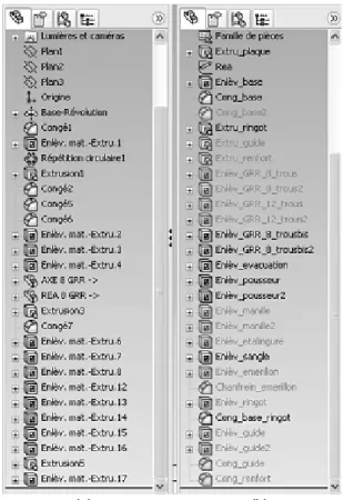
Figure 7 represents the feature management diagram of the old version of a flange created manually and the new version of the same flange, created with the program. We notice that the diagrams differ. In the old version the features are created as the flange is constructed. In the new one the features are organized by functions. We also notice that some features of the new version are not used. These features represent functions not required by the customer and so not present in the functional requirements.
(a) (b) Figure 7: Feature diagrams of the old version of a flange
(a) and the new one (b).
The referencing of the flanges and pulleys is automated in the software. It means that if the part or the assembly is new the reference is created. If the part is old the reference is copied. In both cases the references are added to the layouts and the BOMs.
When the product is an assembly we add a functionality to automate the creation of the BOM, based on the CAD BOM functionality.
The drawings were created automatically in order to keep a paper record of the pulleys and its parts.
A table for the quotes was also made to calculate the price of a pulley depending on its functionalities. Each function has a price depending onthe number of sheaves and the diameter of the fag end. Adding all the prices of the functions required by the customer we obtain the global quote of the pulley.
4.5 Conclusions and discussions on the case study of a type 2 company
First the software carries out a needs analysis. Then it produces the CAD model for the specific pulley, shows the quote, opens a reference if necessary and creates the layouts and the BOM. The design time for a new pulley has gone from hours to minutes.
Moreover there is now a single CAD file to manage, with an associated table of parameter definitions for the 1200 pulley references. With the record of modifications of the parameter definitions and the functional requirements of each sale we can find an old version of a pulley directly from this CAD file.
We propose a global approach to meet the specific PLM needs of this company. The implementation of the software based on this approach and the results that we have obtained prove that the approach is in phase with the needs of this kind of company, a type 2 SME in the mechanical engineering industry.
Nevertheless we intentionally chose a family of well-known products. We have to think of the feasibility of this
[11] Scheer, A.W., 1998, ARIS. Handbook on Architectures of Information Systems, Springer-Verlag., p541-566.
approach if we choose a new range of products. Many parameter definitions were obtained with an empirical value, and it could be difficult to assume those coefficients
for a new product range. [12] GERAM, 1999, GERAM: Generalised Enterprise Reference Architecture and Methodology v1.6.3, IFIP–IFAC Task Force on Architectures for Enterprise Integration.
5 CONCLUSIONS AND PROSPECTS
We proposed and implemented a global approach to meet PLM needs of a type 2 company. The results obtained confirm that this solution meets the needs in terms of PLM of this type of company. But in an extended enterprise, we cannot limit our approach to one type of company. It must be possible to link integrators, detail parts producers and mould makers or machine tool producers in order to bring a modern industrial project to fruition. That is why our next industrial cases will be an elementary part producer and a machine tool producer. That will enable us to underline the specific problems of the other type of companies and of the other life-cycle steps such as the BOM management or the plan of procedure management in the industrialisation or production phases.
[13] Doumeingts, G., and al., 1998, Decisional Modelling using the GRAI Grid. Handbook on Architectures of Information System, Springer-Verlag., p313-338. [14] Williams, T.J., 1994, The Purdue Enterprise
Reference Architecture, Computers in Industry 24, p141–158.
[15] Chambolle, S., 1999, Un modèle produit piloté par les processus d’élaboration : Application au secteur automobile dans l’environnement STEP, Thèse de doctorat, Ecole Centrale Paris.
[16] El Khalkhali, I., Ghodous, P., Martinez, M., Fravel, J., 2002, An information infrastructure to share product models using STEP standard, 9th IPSE international conference on concurrent engineering: research and applications, Cranfield University, 27th-31st July 2002.
6 REFERENCES
[1] Cetim, 2007, Enquête de besoin sur le travail collaboratif, Document interne.
[17] ISO 10303-1, 1994, Industrial Automation Systems and Integration - Product Data Representation and Exchange - Part 1: Overview and Fundamental Principles. ISO - International Organization for Standardization.
[2] Cetim, 2007, Etude sur les besoins en PLM, Document interne.
[3] Terzi, S., 2005, Element of Product Lifecycle Management: Definitions, Open Issues and Reference Models, PhD thesis, Université Henry
Poincaré Nancy-I. [18] ISO 10303-11, 1994, Industrial Automation Systems and Integration - Product Data Representation and Exchange - Part 11: Description Methods: The EXPRESS Language Reference Manual. ISO - International Organization for Standardization. [4] CIMdata Inc., 2003, Product Lifecycle
Management “Empowering the future of business”. [5] Bacha, R., 2002, De la gestion des données
techniques pour l’ingénierie de production. Référentiel du domaine et cadre méthodologique pour l’ingénierie des systèmes d’information techniques en entreprise, Thèse de doctorat, Ecole Centrale Paris.
[19] ISO 10303-214, 1998, Industrial Automation Systems and Integration - Product Data Representation and Exchange - Part 214: Application Protocol: Core Data for Automotive Mechanical Design Processes. ISO - International Organization for Standardization.
[6] Nguyen Van, T., 2006, System engineering for collaborative data management systems: Application to design/simulation loops, PhD thesis, Ecole Centrale Paris.
[20] ISO 10303-239, 2005, Industrial Automation Systems and Integration - Product Data Representation and Exchange - Part 239: Application Protocol: Product Life Cycle Support. ISO - International Organization for Standardization. [7] Delplace, J.C., 2004, L’Ingénierie numérique pour
l’amélioration des processus décisionnels et opérationnels en fonderie, Thèse de doctorat, Ecole
Centrale de Nantes. [21] PDM Schema, 2001, PDM Schema v1.2 : http://www.pdm-if.org/pdm_schema/index.html [8] White, S.A., 2004, Introduction to BPMN :
http://www.bpmn.org/ [22] Suh, N.P., 1990, The Principle of Design, Oxford University Press.
[9] Labrousse, M., Bernard, A., Veron, P., Process/Product/Resource integration, in Tools and Methods of Competitive Engineering, Edited by Imre Horwvath, Paul Xirouchakis, Volume1, pp. 384-394, Millpress Rotterdam Netherlands, ISBN 90-5966-018-8, 2004.
[23] Harutunian, V., Nordlund, M., Tate, D., Suh, N.P., 1996, Decision Making and Software Tools for Product Development Based on Axiomatic Design Theory, CIRP Annals – Manufacturing Technology, Volume 45, Issue 1, Pages 135-139. [24] Suh, N.P., Do, S.H., 2000, Axiomatic Design of
Software Systems, CIRP Annals - Manufacturing Technology, Volume 49, Issue 1, Pages 95-100. [10] Kosanke, K., Zelm, M., 1999, CIMOSA modelling