HAL Id: hal-00468932
https://hal.archives-ouvertes.fr/hal-00468932
Submitted on 26 Jun 2019
HAL is a multi-disciplinary open access
archive for the deposit and dissemination of
sci-entific research documents, whether they are
pub-lished or not. The documents may come from
teaching and research institutions in France or
abroad, or from public or private research centers.
L’archive ouverte pluridisciplinaire HAL, est
destinée au dépôt et à la diffusion de documents
scientifiques de niveau recherche, publiés ou non,
émanant des établissements d’enseignement et de
recherche français ou étrangers, des laboratoires
publics ou privés.
Technology-Oriented Optimization of the Secondary
Design Parameters of Robots for High-Speed Machining
Applications
Sébastien Briot, Anatol Pashkevich, Damien Chablat
To cite this version:
Sébastien Briot, Anatol Pashkevich, Damien Chablat. Technology-Oriented Optimization of the
Sec-ondary Design Parameters of Robots for High-Speed Machining Applications. ASME 2010
Inter-national Design Engineering Technical Conferences & Computers and Information in Engineering
Conference IDETC/CIE, Aug 2010, Montréal, Canada. pp.DETC2010-28107,
�10.1115/DETC2010-28107�. �hal-00468932�
TECHNOLOGY-ORIENTED OPTIMIZATION OF THE SECONDARY DESIGN PARAMETERS OF
ROBOTS FOR HIGH-SPEED MACHINING APPLICATIONS
Sébastien Briot a, b Anatol Pashkevich a, b, Damien Chablat a
a
Institut de Recherches en Communications et Cybernétique de Nantes (IRCCyN), UMR CNRS 6597
1 rue de la Noë, BP 92101, 44321 Nantes Cedex 3 France
b
Ecole des Mines de Nantes
La Chantrerie, 4 rue Alfred-Kastler, BP 20722, 44307 Nantes Cedex 3 France
Professor and author of correspondence, Phone: +33 2 51 85 83 00, Fax: +33 2 51 85 81 99, Email: Anatol.Pashkevich@emn.fr.
ABSTRACT
In this paper, a new methodology for the optimal design of the secondary geometric parameters (shape of links, size of the platform, etc.) of parallel kinematic machine tools is proposed. This approach aims at minimizing the total mass of the robot under position accuracy constraints. This methodology is applied to two translational parallel robots with three degrees-of-freedom (DOF): the Y-STAR and the UraneSX. The proposed approach is able to speed up the design process and to help the designer to find more quickly a set of design parameters.
1 INTRODUCTION
Parallel kinematic machines (PKM) are commonly claimed to offer several advantages over their serial counterparts, such as high structural rigidity, better payload-to-weight ratio, high dynamic capacities and high accuracy [1–3]. Therefore, they are prudently considered as promising alternatives for many modern material processing operations, especially in automotive and aerospace industry, in which high accuracy positioning and high-speed motions of a work tool are required. Thus, PKM have gained essential attention of a number of companies and researchers. However, most of the existing PKM still suffer from two major drawbacks, namely, a complex workspace and highly non-linear input/output relations [4, 5].
For most of PKM, the performances vary considerably for different points in the workspace and for different directions at one given point. This is a serious disadvantage for machining applications [6, 7], which require regular workspace shape and acceptable performances throughout. In milling applications,
for instance, the machining conditions must remain constant along the whole tool path [8]. Nevertheless, in many research papers, this criterion is not taken into account in the algorithmic methods used for the optimization of robots [9, 10].
Our previous work [11] was focused on the optimal design of the primary geometric parameters (length of links, shape of the base, etc.) of robots for given geometric, kinematic and kinetostatic properties (e.g. size of the workspace, maximum speeds, forces transmission, accuracy). Contrary to many works on optimal design of parallel robots (see for example [12, 13]), it was proposed to use technology oriented indices in order to define the optimal design parameters. This work was the first step of an optimization process. Indeed, the previously proposed algorithm does not allow obtaining any information about the value of the secondary design parameters (e.g. shape of links, size of the platform, etc.). For finding these values, other constraints should be considered, such as constraints derived from the robot dynamics (acceleration capacities), its elastostatic behaviour or its natural frequencies.
Thus, this paper is the continuity of work [11]. Here, a new methodology for the optimal design of the secondary design parameters of parallel kinematic machine tools is proposed. This approach aims at minimizing the total mass of the robot under position accuracy constraints. The main contribution of this paper is in the area of CAD methodology and application of the operation research methods to the integrated design optimization of complex mechanical structures, such as parallel robots.
The paper will be divided as follows. In the second part, the design problem and methodologies are explained. In the third section, the performance measures, design constraints and objectives are presented and the optimization procedure is described. It is applied to an industrial case study in part four. Finally, in the last section, conclusions are drawn.
2 DESIGN PROBLEM AND METHODOLOGY
Design of a robot involves simultaneous optimisation of many types of criteria that may evaluate the kinematic, the kinetostatic or also the dynamic properties. However, the design of a manipulator, once its architecture is known, may be decomposed into two steps:
- Step 1: find the values of the primary geometric parameters (length of links, base radii, joint limits, etc.) using geometric, kinematic and kinetostatic constraints and objectives (workspace, velocity, effort transmission, etc.); - Step 2: find the values of the secondary geometric
parameters (cross-section, shape of links, etc.) using dynamic, elastostatic and/or elastostatic constraints and objectives (acceleration capabilities, maximal deformations of the tool, natural frequencies of the structure, etc.). Step 1 has been studied in many works [9-13]. Indeed, as it is based on simple geometric, kinematic and kinetostatic models, this step is mostly the simplest to achieve. This is not the case of the second optimization level which requires more complicated and time-consuming models. For example, in order to obtain a very accurate elastostatic model, finite element analysis (FEA) should be used. However, because of the huge number of elements used for the meshing of the robot, such model cannot be integrated in a design optimization process.
Here, a design methodology that uses more efficient models is proposed. This will allow obtaining near-optimal results in a reasonable computational time. Then, these results may be introduced in more accurate, but more time-consuming models, in order to verify that they respect the design specifications. If they do not, two solutions are possible: (i) to improve the accuracy of the model used in the optimization loop or (ii) to modify the design constraints (with safety coefficient) in order to obtain acceptable results. It should be mentioned that, even if several optimization loops are necessary, this approach will considerably speed up the design process.
To formulate the design problem, let us define the manipulator geometry by the mapping g: W, where =
1 × … n and = p1 × … pn denote respectively the
configuration space and the workspace. i are the joint
coordinates and pi are the coordinates of the end-effector. n is
the number of degrees of freedom (DOF). Besides, for each workspace point P W, let us define the matrices Kd(P, ),
Ks(P, ), Kv(P, ), that describe various mechanical properties
of the manipulator (dynamics, stiffness, etc.) for any given set of the design parameters . Let us also assume that for each type of the matrices K, {d, s, …}, there are defined physically consistent scalar measures (K), {i, a, …} that may be directly included in the design objectives or constraints. Some examples of such measures (input efforts, accuracy of the tool, etc.) are presented in the following sub-sections.
Similarly, for the global evaluation of the manipulator, let us introduce the performance measures (g, ), {m, e, n, …}, that depend both on the adopted geometrical structure g and the physical parameters of the links . Examples of the global measures include the total mass of the manipulator, the maximal admissible input effort, the minimal admissible natural frequency, etc.
Then, following the general methodology adopted for the considered application area (high-speed machining), the design optimisation problem can be stated as achieving the best value of the performance indices
( , )min,
π
π
g (1)
subject to the constraints
K(P π, ) S, , (2) that must be satisfied for all points of the workspace W which includes the manufacturing task. Since in practice this problem cannot be solved by the direct search methods, in the following subsections, there will be presented the discretisation scheme and relevant optimisation algorithms allowing to obtain desired solutions in reasonable time.
3 PERFORMANCE MEASURES AND DESIGN
CONSTRAINTS
In the following of this paper, it is assumed that the primary design parameters are already known. Thus, let us now present the procedure for optimization of the secondary design parameters.
3.1 Design constraints and objectives
Several indices may be used in order to define the secondary geometric parameters of the robots. As an example, it is possible to choose the maximal deformations under a load (variable or constant), the first natural frequency, which indicates the way a mechanism tends to vibrate, the input efforts, that are needed in order to observe the dynamic capacities of the mechanism, etc. All these indices are strongly related to the shape of the links of the robot and their material properties (density, stiffness, etc.). However, some of them seem to be more important, such as the required input efforts and the maximal deformations. Indeed, if manufacturers have no problems to define a fixed strong value for a maximal admissible accuracy or for the dynamics capacities of the robot (acceleration), this is not the case with the natural frequencies, for which the minimal admissible value may vary up to 50%, depending on the manufacturer’s opinion. Therefore, in the following of this paper, proposed indices are only based on the computation of the maximal deformations and maximal input efforts.
Now, we have to choose if the maximal deformations and the maximal input efforts will be used as constraints or as objectives. Indeed, it seems quite obvious to use the maximal deformations as constraints because, mostly, the desired accuracy of the mechanism is given. For the input efforts, the question is a bit more complex. The input efforts allow characterizing the dynamic properties of the robot (acceleration capabilities) and also to choose the well-appropriated actuator during the design process. If the actuator is powerful enough to accept the desired input efforts, the mechanism will be able to accelerate properly. If not, the mechanism will accelerate more slowly. Of course, most powerful actuators will be more expensive. So, the input
efforts should not be considered as mechanical constraints of the mechanism, but as design objectives in order to minimize the cost of the robot and also its power consumption.
In the next parts, the design constraints and the design objectives are defined.
3.2 Design constraints: the deformations
The modelisation of the deformations used in this part has been presented in [14]. This model, which combines advantages of the traditional methods (the finite element analysis [15, 16], the matrix structural analysis [17, 18] and the virtual joint method [19, 20]) is based on a multi-dimensional lumped-parameter model that replaces the link flexibility by localized 6-DOF virtual springs that describe both the linear/rotational deflections and the coupling between them. In addition, it employs a new solution strategy of the kinetostatic equations, which allows computing the stiffness matrix for the overconstrained architectures, including the singular manipulator postures. This gives almost the same accuracy as FEA but with essentially lower computational effort because it eliminates the model re-meshing through the workspace.
This model states that the deformations ti of the extremity
of the leg i of the manipulator are related to the efforts fi
applied to its extremity via the relation:
0 t q f 0 J J S i i i T i q i q i δ δ , Si Ji
Ki 1JiT (3) where qi represents the passive joints displacements of theleg i, i
K is the stiffness matrix describing the rigidity of all the elements of the leg i and Ji , J are the Jacobian matrices iq
relating the displacements of the extremity of the leg i to the spring deflections i and passive joint displacements qi,
such as i i i i q i J q J θ t δ δ δ , i i i q q t J , i i i θ t J . (4)
After the stiffness matrices Ki for all kinematic chains are
computed, the stiffness of the entire manipulator can be found by simple addition:
n i i m 1 K K . (5)Then, once Km is known, the deformations t of the tool
under a load f may be computed as: f K
t 1
δ
m . (6)
Here, it is clear that the matrix Km depends on the position
of the end-effector, and as a consequence, that the deformations vary with the position of the robot in its workspace.
We would like to mention that the vector t is a six
dimensional vector, of which three first components, denoted by the vector tt, represent the translational deformations of
the tool of the robot, and the three last components, denoted by the vector tr, its rotational deformations.
So, using the proposed elastostatic modelisation, let us express the design constraints. The vector containing all or some components of the vector tt (tr, resp.) is denoted as p
(, resp.). pmax (max, resp.) is the maximal admissible
value for the norm of the vector p (, resp.) wherever in the workspace W. Thus, the design constraints may be written as:
max δ ) δ ( max p p W , (7a) max δ ) δ ( max Φ W . (7b)
3.3 Design objective: minimisation of the input efforts
The input efforts of a manipulator depend on its position, velocity and acceleration, as well as the shape and material density of its links. However, it is clear that, at a design stage, one cannot consider the velocity and the acceleration of the manipulator, as it depends on the required application. So the number of sets of admissible velocities and accelerations is infinite. Moreover, these parameters may be also optimized in a next step [21], but only when the type of application is given, which is not the case now.
From the shape Si and material density i of a link i, one
may found its mass and matrix of inertia. It could be shown that the parameters that have the most influence on the input efforts of a manipulator (for given positions, velocities and accelerations) are the masses of the links. The influence of the axial moments of inertia is negligible compared to the influence of the masses. Therefore, the problem of minimizing the input efforts may be reduced to the minimization of the total mass mrobot of the robot:
, min ) , ( ,ρ S ρ S robot m where S = [S1,… , Sn]T, = [1,… , n]T(8)
(n being the total number of links) subject to the constraints
max δ ) δ ( max p p W
and max(δΦ)δmax
W
. (9)
In the next part, the algorithm used for the design procedure is presented.
3.4 Design procedure
The simplest way to find the design parameters is to apply the following straightforward algorithm:
for = min to max
compute the deformations p(P, ) under a load f for
any point P of the workspace W if max(δp(P,π))δpmax
W and maxW (δΦ(P,π))δmax
then compute mrobot() end end
(
)
min
arg
π
π
π robot optm
The main drawback of this algorithm is that, as it computes the deformations of the robot for all workspace points P, it is very time-consuming. Thus, it should be simplified.
Two ways may be followed in order to accelerate the computing process. The first one consists in assuming that the largest deformations will appear at the boundary of the studied workspace. Thus, only a short number of points are tested. The assumption is realistic because, kinematically speaking, i.e. analyzing the Jacobian matrix, the properties of most of robots are better in the centre of the workspace than on its boundary. As the stiffness matrix of the robot depends partially on the
Jacobian matrix, the assumption is quite realistic. However, there are no direct proofs of that. But this considerably speeds up the routine process.
The second way is to use the goal attainment programming. The goal attainment optimization allows generating specific Pareto-optimal solutions. Let us apply the goal-attainment technique that yields the following nonlinear programming formulation: π , min (10) subject to i h h f w fi( ) i i ; ( ) i; 0 0 π π
(11)Here, is an unrestricted scalar variable, wi0 are designer
selected weighting coefficients, and 0 i
f are the goal to be realized for each design objective. For computational conveniences, the design constraints have been transformed in the scalar form h(π)hi0. In this formulation, minimization
of tends to force the specifications to meet their goal. If, at the solution point, is negative, the goals have been over-attained; if is positive, then the goals have been under-attained. The method is appealing since it is possible for the designer to specify unrealizable objectives and still obtain a solution which represents a compromise. For more information about the goal-attainment optimization, the reader may refer to [22].
4 APPLICATION EXAMPLES
4.1 Industrial problem
Let us demonstrate the efficiency of our design approach on a concrete problem coming from the industrial sector of the region of Nantes (France).
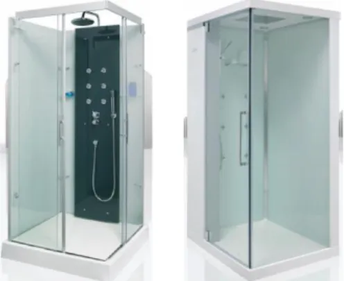
One of the most important activity areas of this region is the manufacturing of bathroom components (shower cabin, washbasin, bathtub, etc. as shown in Fig. 1). Most of parts used during the assembly process of the bathroom component are flat and made of thermosetting materials. The main operations achieved on these parts is trimming, i.e. the suppression of the edges of the parts in order to obtain a good surface roughness.
The machines tools that are used for the trimming of these bathroom components must be designed such as they attain the following characteristics:
- workspace Wabc of size {2.5 m × 2.5 m × 0.5 m}; - ||vxy|| = 60 m/min (vxy contains the components of the
platform velocity vector v in the xy plane);
- ||fxy|| = 300 N (fxy contains the components of the external
effort vector f in the xy plane);
- ||pxy|| = 0.25 mm (pxy contains the components of the
platform deformations vector p in the xy plane).
Looking at these requirements, and from our industrial experience, several types of robots may be envisaged, such as the Y-STAR [23], the UraneSX [24], the Orthoglide [3], the Hybridglide [25], the 3-UPU [26], etc. However, because the workspace is not a cube, but a flat parallelepiped, it appears that only two kinds of architectures, that have non-orthogonal arrangement of legs and that are already used in machining process, seem to be best adapted: the Y-STAR (Fig. 2) and the UraneSX (Fig. 3). It should be mentioned that, in our study, the prismatic guides of the UraneSX are vertical.
Figure 1. Typical examples of bathroom components.
In our previous work [11], the optimal primary geometric parameters have been found, taking into account the above requirements. The values of the optimal lengths of legs for the two robots were 2.16 m for the Y-STAR and 4.62 m for the UraneSX. The value of the optimal radius of the base circumcircle for the UraneSX was 2.77 m.
Starting from these parameters, it is proposed to achieve the optimization of the secondary geometric parameters of these two robots. The assumption is made that the base, the platform and the feet are designed such as they may be considered rigid. The only deformable links are the bars of the parallelograms. This assertion is quite realistic when considering the huge length of the legs. So, the only parameters to optimize are:
- the radius of platform circumcircle (i.e. the circle passing through the points Bi of Figs. 2a and 3a), denoted as RTool;
- the length 2d of the small links of the parallelograms (see Figs. 2a and 3a);
- the cross-sections SBar of the long bars of parallelograms
(see Figs. 2a and 3a)
Let us first present the elastostatic modelisation of the two robots.
4.2 Elastostatic modelisation
As presented in Figs. 2 and 3, both manipulators have similar architectures (Fig. 41). They may only be differentiated by the position and orientation of the axes of the actuated prismatic pairs. Therefore, their elastostatic models may be obtained in similar ways.
As the feet, base and platform are considered rigid, each chain of Fig. 4 may be decomposed into two subchains (Fig. 5) which are linked to the same foot. The subchains may be described as:
(a) a rigid link between the manipulator base and the ith actuator (part of the base platform) described by the constant homogeneous matrix i
Base
T ;
(b) a 1-DOF actuating joint which is defined by the homogeneous function matrix
iaq0
V , where i
q0 is the
actuated coordinate;
(c) a rigid foot linking the actuating joint and the axis of the parallelogram, which is described by the constant homogeneous matrix TFooti ;
1
On this picture, P stands for an actuated prismatic joint, and U for a passive universal joint.
(a)
(b)
Figure 2. The robot Y-STAR: (a) kinematic chain and (b)
prototype.
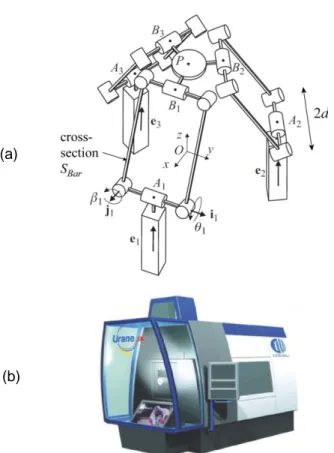
(a)
(b)
Figure 3. The robot UraneSX: (a) kinematic chain and
(b) prototype.
Figure 4. Architecture of the Y-STAR and the UraneSX.
Figure 5. Modelisation of the subchains.
(d) a 2-DOF passive U-joint at the beginning of the bar of the parallelogram, allowing two independent rotations with angle i
q1 and i
q2, which is described by the
homogeneous matrix function VU
q1i,qi2
;(e) a rigid bar linking the two axis of the parallelogram, which is described by the constant homogeneous matrix
Bar
T ;
(f) a 6-DOF virtual spring describing the bar mechanical stiffness, which is defined by the homogeneous matrix function Vs
0i,...,
5i
where
0i,
1i,
2i
,
3i,
4i,
5i
are the virtual spring coordinates corresponding to the spring translational and rotational deflections, respectively; matrix Vs is composed of six elementary transformations;(g) a 2-DOF passive U-joint at the end of the bar of the parallelogram, allowing two independant rotations with angle q3i and
i
q4, which is described by the
homogeneous matrix function VU
q3i,q4i
;(h) a rigid link from the manipulator leg to the end-effector described by the constant homogeneous matrix transformation i
Tool
T . In the following simulations, the controlled point of the end-effector is considered to be located at the extremity of a milling cutter of length equal to 20 cm.
The corresponding mathematical expression defining the end-effector location subject to variations of all above defined coordinates of a single kinematic chain i may be written as follows:
i Tool i i U i i s Bar i i U i Foot i a i Base i q q q q q T V V T V T V T T 4 3 5 0 2 1 0 , ,..., ... ... , , i = 1 to 6 (12) In the rigid case, the virtual joint coordinates i i5 0,...,
areequal to zero, while the passive and active coordinates
i i
q
q0,..., 4 are obtained through the inverse kinematics, ensuring
that all matrices Ti are equal to the prescribed one that
characterizes the desired spatial location of the moving platform (kinematic loop-closure equations). Particular expressions for all components of the product (12) may be easily derived using standard techniques for homogeneous transformation matrix.
Now, matrices Ji , Jiq presented at Eq. (3) have to be
found. The matrix Ji may be obtained from the differentiation of the matrix Ti with respect to the spring parameters ij (j = 0 to 5), at the point 0
i j , considering that
0 0 0 0 ' 0 ' ' ' ' 0 ' ' ' ' 0 iz ix iy iy ix iz ix iy iz R ij i j i j L ij i j i p p p j H V H T (13)where the first and the third multipliers are the constant homogenous matrices which do not include the displacement
i j
, and the second multiplier corresponds to the derivative of the elementary translation or rotation corresponding to ij. In the right-hand term, symbol “ ' ” stands for the derivation of the variables with respect to ij. Therefore, p'ix, p' and iy p'iz
(resp.
'ix, 'iy and
'iz) correspond to the small translationsalong (resp. rotations about) x, y and z axes of the extremity of the leg i due to the variation of the parameter i
j
. The Jacobians i
q
J can be computed in a similar manner, but
the derivatives are evaluated in the neighbourhood of the “nominal” values of the passive joint coordinates i
j
q (i = 1, to
4) corresponding to the rigid case (these values are obtained from the inverse kinematics.
Once these matrices are obtained, the stiffness matrix of the robots may be easily obtained using expressions (3) to (5).
4.3 Computation of the total mass
The total mass of the robot is obviously the sum of the masses of each of its links, i.e. the masses of the three feet plus the six axes and bars of the parallelograms plus the platform.
The length of the bars of the parallelograms is already known here. But this is not the case of their shape, which should be properly defined by an analysis of the effort transmission and deformations of the mechanism. Indeed, looking at the two robots under study, it appears that the bars of the parallelograms have only to support traction/ compression and torsion solicitations.
It is known (and it could also be easily demonstrated) that the best appropriated shape of bars able to best resist to these
Figure 6. Attachment of the bars of the parallelogram
onto the platform.
types of solicitations is the hollow cylinder. Thus, once this shape is fixed, one can compute the mass of one bar of a parallelogram:
Bar Bar
Bar Bar Bar BarBar
Bar l R r l S
m
2 2
. (14)where Bar is the density of the material, lBar is the length of
the bars, RBar is the external radius of the cross-section, and rBar the internal radius (RBar and rBar are parameters that should
be defined during the optimization process). SBar is the value
of the cross-section. It should be mentioned that, for any fixed value of SBar, the cross-section that has the best torsional
stiffness is the cross-section with the largest value of RBar.
Therefore, for one given maximal value RBarmax of RBar, rBar
should be equal to
Barmax 2 Bar/Bar R S
r . (15)
The mass of the feet is directly linked to their shape and length (which is considered equal to 2 d, where d is a parameter that should be defined during the optimization process). In a first approximation, it is considered that these feet should have the shape of cylinders. This shape is not the best one, but at this design stage, it is sufficient to give an approximation of their mass. It will be refined in another step using CAD/FEA software. So, their mass is equal to
d k R
d
mFoot Foot Foot 1 2
2
2
. (16)where Foot is the density of the material, and RFoot is the
external radius of the cross-section. The parameter k1 regroup
all constant terms of expression (16).
Finally, the mass of the platform will also vary with its shape. It is commonly considered that the platform may be kinematically represented by a circle. Therefore, it will be considered here that its shape is a cylinder. Once again, this is not the best solution, but at this design stage, it is sufficient to give an approximation of their mass. It will be also refined in another step using CAD/FEA software. So, its mass is equal to
2 2 2 Tool Tool Tool Tool h R k R m
. (17)where Tool is the density of the material, h is the height of the
cylinder and RTool is the platform radius (which is a parameter
that should be defined during the optimization process). The parameter k2 regroup all constant terms of expression (17).
Finally, the total mass of the platform is equal to
2 2 1
6
6 BarlBarSBar k d k RTool
It should be mentioned here that, to avoid interferences between two adjacent parallelograms links, the radius RTool of
the platform should be superior to 2 d/ 3 (Fig. 6).
In the next subsection, a design procedure that allows finding the optimal design parameters SBar, d and RTool will be
proposed.
4.4 Optimization results
Before using the optimization algorithm proposed in section 3.4, the lower and upper bounds of the search intervals for the parameters d, SBar and RTool have to be fixed. These intervals
are:
- d [0.1 m, 0.7 m]; the lower limit of 0.1 m is set because of design issues. Indeed it is difficult to design parallelograms with small axes and a lower limit for d of 0.1 m is considered as a minimal acceptable value;
- RTool [2 d/ 3, 0.8 m];
- SBar [10-5 m², 0.01 m²].
The obtained results are presented below.
4.4.1 Comparison between the alternative solutions
At this step, as the exact form of the feet and of the platform is not known, one way to proceed is to make the parameters k1
and k2 vary. This will allow the designer to test several
potential designs with CAD/FEA software and to find, in the last step of the optimization process, the most adapted one.
Here, the used values of parameter k1 are 25, 100 and 200.
These values correspond to axes of parallelogram made of aluminium, of which radius is equal 5 cm, 10 cm and 15 cm respectively.
The lower value of 5 cm is chosen because, in our previous work [11], it was shown that the maximal rate between the force applied to the platform and the force applied to the feet was about 10. It means that, if the force applied to the platform is 300 N, the maximal force applied to the feet will be of 3000 N. Let us consider a beam of length 0.4 m. The value of 0.4 m is chosen here as it corresponds to the medium value of the search interval for parameter d. It could be shown that the deformation of a beam under a load of 3000 N, of which the circular section’s radius is 5 cm, is a bit less than 0.25 mm (0.25 mm being the maximal desired value of the end-effector deformation). The other values for the radius (10 cm and 15 cm) are used because the exact form of the feet is not known. Thus, it is preferable to make the radius vary, in order to test several potential design with CAD software and to find the most adapted one.
The used values of parameter k2 are 250, 500, 750 and
1000. These values correspond to platform of height comprised 3 cm, 6 cm, 9 cm and 12 cm. As it is difficult to know the real shape of the platform, the lower value of 3 cm is chosen because it is approximately the width of the platform of the Orthoglide robot [3] manufactured by Symetrie® and located at the IRCCyN (France). The other values are used because the exact form of the platform is not known. Thus, it is preferable to make the height of the platform vary, in order to test several potential design with CAD software and to find the most adapted one.
In a first step, let us analyze the evolution of the design parameters as a function of the desired accuracy of the platform. It is proposed to vary the value of pmax from 0.01
mm to 0.5 mm. For any set of parameters k1, k2 and pmax, the
values of the optimal design variables are computed. The less time-consuming algorithms proposed in section 3 are used. The results are presented at tables 1 and 2. It is only presented one table per robot for the two algorithms proposed above, because the obtained results in the two cases are identical. Thus, the assumption made in section 3 for accelerating the computing process was correct, i.e. in this case, the worst points for accuracy are located at the boundary of the workspace.
It may be observed for the UraneSX (Y-STAR, resp.) that, for any fixed value pmax ≤ 0.1 mm (pmax = 0.01 mm, resp.),
the values of design variables SBar, d and RTool evolve as a
function of the parameters k1 and k2. This is not the case for
pmax = 0.5 mm (pmax ≥ 0.05 mm, resp.). In this case, the
design parameters remain constant whatever is the values of k1
and k2. The optimal value of d is 0.1 m, which was the lower
bound fixed in our optimization algorithm. As previously said in section 4.4, this lower limit was fixed because of design issues. The reason for which all the values of the design variables SBar, d and RTool are constant for pmax = 0.5 mm
(pmax ≥ 0.05 mm, resp.) is that optimal solutions will appear
for d < 0.1 m, but it is not possible to pass though this limit. Thus, because of the huge impact of the feet platform masses on the total mass of the robot, the algorithm converge to the sizes of platform and feet that will keep the total mass as small as possible.
It could also be observed that, when the parameters k1 and
k2 increase, i.e. when the cross-section of the feet and the
height of the platform cylinder increase, the optimal robots will be obtained when the values of the length d of the axes of the parallelograms and of the platform radius RTool decrease.
This is due to the fact that the mass of the feet and of the platform largely increase with the increase in the parameters d and RTool. When this appears, it may also be observed that the
cross-section of the bars of the parallelograms increases. This phenomenon is due to the fact that, the smaller the length d of the axes, the poorer the torsional stiffness of the parallelograms. Therefore, it is necessary to increase the cross-section of the bars in order to assure the good stiffness of the entire mechanism.
Finally, it should be mentioned that, for identical sets of parameters k1, k2 and pmax, the mass of the Y-STAR is lower
than that of the UraneSX.
4.4.2 Optimization results for bathroom components milling
In order to be sure that the obtained robot will not suffer from a lack of accuracy due to non modelized phenomena (such as clearance, elasticity of joints, etc), some safety coefficient is applied to the value of ||pxy||. The corrected value is fixed to
0.1 mm.
First, the height of the platform was fixed to 3 cm, i.e. k2 =
250. For pmax = 0.1 mm, the maximal value of d is 0.22 m. It
could be shown that the maximal deformation of the foot, represented by a aluminium beam of length 0.22 m, under a load of 3000 N (see section 4.4.1), of which cross-section’s radius is 10 cm, is about 0.002 mm, i.e. it is insignificant compared with the deformations of the bars of the parallelogram. Thus, parameter k1 is fixed to 100.
Table 1. Values of the secondary geometric parameters
of the UraneSX, for bars of the parallelograms made of aluminum and for max
Bar R = 7.5 cm. pmax (mm) k1 k2 m (kg) SBar (cm²) d (m) RTool (m) 0.01 25 250 168 17,93 0,5 0,29 500 185 19,29 0,42 0,24 750 197 20,76 0,36 0,21 1000 208 21,37 0,34 0,20 100 250 202 19,73 0,4 0,23 500 214 20,76 0,36 0,21 750 223 22,07 0,32 0,18 1000 232 22,88 0,3 0,17 200 250 238 21,37 0,34 0,20 500 247 22,88 0,3 0,17 750 254 22,88 0,3 0,17 1000 261 23,80 0,28 0,16 0.05 25 250 49 4,75 0,28 0,16 500 55 5,21 0,24 0,14 750 59 5,51 0,22 0,13 1000 62 5,87 0,2 0,12 100 250 67 5,87 0,2 0,12 500 71 5,87 0,2 0,12 750 73 6,30 0,18 0,10 1000 76 6,84 0,16 0,09 200 250 86 6,84 0,16 0,09 500 88 6,84 0,16 0,09 750 89 7,51 0,14 0,08 1000 91 7,51 0,14 0,08 0.1 25 250 30 2,75 0,22 0,13 500 34 3,15 0,18 0,10 750 36 3,42 0,16 0,09 1000 38 3,42 0,16 0,09 100 250 44 3,42 0,16 0,09 500 45 3,75 0,14 0,08 750 47 4,17 0,12 0,07 1000 48 4,17 0,12 0,07 200 250 56 4,70 0,1 0,06 500 57 4,70 0,1 0,06 750 58 4,70 0,1 0,06 1000 59 4,70 0,1 0,06 0.5 25 250 10 0,94 0,1 0,06 500 11 0,94 0,1 0,06 750 12 0,94 0,1 0,06 1000 13 0,94 0,1 0,06 100 250 18 0,94 0,1 0,06 500 19 0,94 0,1 0,06 750 20 0,94 0,1 0,06 1000 20 0,94 0,1 0,06 200 250 28 0,94 0,1 0,06 500 29 0,94 0,1 0,06 750 30 0,94 0,1 0,06 1000 30 0,94 0,1 0,06
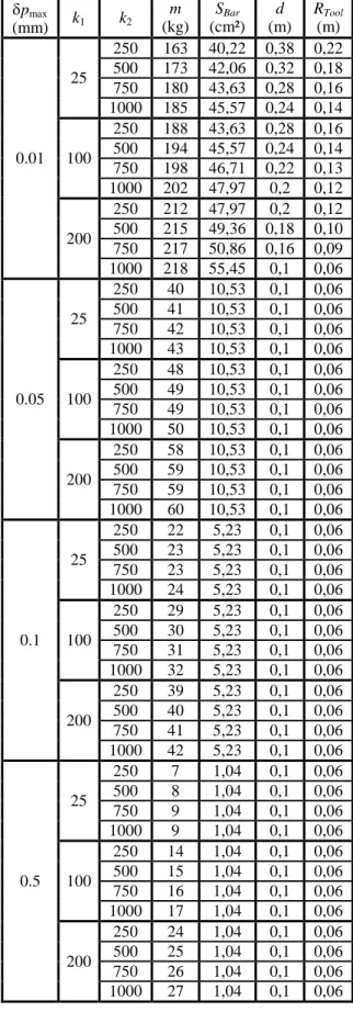
Table 2. Values of the secondary geometric parameters
of the Y-STAR, for bars of the parallelograms made of aluminum and for max
Bar R = 7.5 cm. pmax (mm) k1 k2 m (kg) SBar (cm²) d (m) RTool (m) 0.01 25 250 163 40,22 0,38 0,22 500 173 42,06 0,32 0,18 750 180 43,63 0,28 0,16 1000 185 45,57 0,24 0,14 100 250 188 43,63 0,28 0,16 500 194 45,57 0,24 0,14 750 198 46,71 0,22 0,13 1000 202 47,97 0,2 0,12 200 250 212 47,97 0,2 0,12 500 215 49,36 0,18 0,10 750 217 50,86 0,16 0,09 1000 218 55,45 0,1 0,06 0.05 25 250 40 10,53 0,1 0,06 500 41 10,53 0,1 0,06 750 42 10,53 0,1 0,06 1000 43 10,53 0,1 0,06 100 250 48 10,53 0,1 0,06 500 49 10,53 0,1 0,06 750 49 10,53 0,1 0,06 1000 50 10,53 0,1 0,06 200 250 58 10,53 0,1 0,06 500 59 10,53 0,1 0,06 750 59 10,53 0,1 0,06 1000 60 10,53 0,1 0,06 0.1 25 250 22 5,23 0,1 0,06 500 23 5,23 0,1 0,06 750 23 5,23 0,1 0,06 1000 24 5,23 0,1 0,06 100 250 29 5,23 0,1 0,06 500 30 5,23 0,1 0,06 750 31 5,23 0,1 0,06 1000 32 5,23 0,1 0,06 200 250 39 5,23 0,1 0,06 500 40 5,23 0,1 0,06 750 41 5,23 0,1 0,06 1000 42 5,23 0,1 0,06 0.5 25 250 7 1,04 0,1 0,06 500 8 1,04 0,1 0,06 750 9 1,04 0,1 0,06 1000 9 1,04 0,1 0,06 100 250 14 1,04 0,1 0,06 500 15 1,04 0,1 0,06 750 16 1,04 0,1 0,06 1000 17 1,04 0,1 0,06 200 250 24 1,04 0,1 0,06 500 25 1,04 0,1 0,06 750 26 1,04 0,1 0,06 1000 27 1,04 0,1 0,06
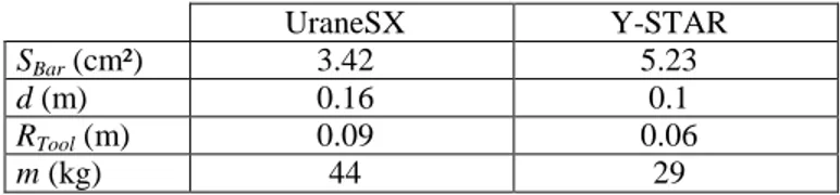
Table 3. Values of the optimal secondary geometric
parameters for the UraneSX and Y-STAR robots.
UraneSX Y-STAR
SBar (cm²) 3.42 5.23
d (m) 0.16 0.1
RTool (m) 0.09 0.06
m (kg) 44 29
Taking into account these parameters and extracting data from tables 1 and 2, the optimal design parameters are presented in table 3.
Our simulations show that manufacturing a Y-STAR for high-speed machining of composite will allow creating robots with a lower mass.
4.5 Discussion
From the obtained results, it should be mentioned several comments. For reason of simplicity and reduction of computational time, it has been considered that the only deformable parts were the links of the parallelograms and that all other elements where rigid. This assumption about the feet and platform is quite realistic because, generally, they are designed such as they have very little deformations. However, the deformations of the bearings and axes that will be used in order to create the universal joints have not been taken into consideration. These parts have generally smaller cross-sections than the others; therefore they may lead to non negligible deformations of the robot. Thus, the proposed model is not sufficient to fix the desired cross-section of the links, and more refined FEA model should be created in order to validate the results. However, these models are complicated and an optimization algorithm using them will be much more time consuming than that proposed here.
So, it should be concluded that the proposed design procedure is not sufficient to definitely fix the design of a robot. However, the algorithm will give the designer an idea of the near-optimal solution that should be confirmed by a FEA analysis. This will be used in order to readjust the values of parameters ki and pmax. After several loops between the
FEA software and the optimization algorithm, the designer will converge to an optimal solution. This optimal solution could be obtained using only FEA model, but the proposed algorithm will considerably accelerate the design process.
5 CONCLUSIONS
In this paper, a new methodology for the optimal design of the secondary geometric parameters of parallel kinematic machine tools was proposed. This approach aims at minimizing the total mass of the robot under position accuracy constraints. This methodology was applied to two translational parallel robots with three DOF: the Y-STAR and the UraneSX. The proposed approach will help the designer to find more quickly an optimal set of design parameters and they will allow considerably accelerating the design process.
To conclude, we would like to mention that our next task in the design optimization of robots will be the analysis and comparison of the results obtained during this optimization process with several other architectures. We also would like to work on the definition of more meaningful criteria (different from the total mass) for the characterization of the robots dynamic properties. Finally, another research perspective is to
more deeply focus on the improvement of the elastic models accuracy, especially in the neighbourhood of singular configurations. Indeed, it appears that near singularities, the elastic behaviour of robots becomes nonlinear. As a result, the classical deformation models are no more accurate enough. Therefore, it is necessary to solve this problem.
6 ACKNOWLEDGMENT
This work has been funded by the French région Pays de la Loire (RoboComposite project).
7 REFERENCES
[1] Merlet, J.-P., 2000, “Parallel Robots,” Kluwer Academic Publishers, Dordrecht.
[2] Tlusty, J., Ziegert, J.C., and Ridgeway, S., 1999 “Fundamental Comparison of the use of Serial and Parallel Kinematics for Machine Tools,” CIRP Annals, Vol. 48(1), pp. 351-356.
[3] Chablat, D., Wenger, P., and Merlet, J.-P., 2004, “A Comparative Study between Two Three-DOF Parallel Kinematic Machines using Kinetostatic Criteria and Interval Analysis”, 11th World Congress in Mechanism
and Machine Science, Tianjin, China.
[4] Tsai, L.W., 1999, “Robot Analysis: the Mechanics of Serial and Parallel Manipulators,” John Wiley and Sons, New York.
[5] Bonev, I.A., “The parallel mechanism information center,” available from: <http://www.parallemic.org>. [6] Kim, J., and Park, C., 1997 “Performance Analysis of
Parallel Manipulator Architectures for CNC Machining Applications,” Proceedings of the IMECE Symposium on
Machine Tools, Dallas, TX.
[7] Wenger, P., Gosselin, C.M., and Chablat, D., 2001, “A Comparative Study of Parallel Kinematic Architectures for Machining Applications,” Proceedings of the 2nd
Workshop on Computational Kinematics, Seoul, Korea,
pp. 249-258.
[8] Rehsteiner, F., Neugebauer, R., Spiewak, S., and Wieland, F., 1999, “Putting parallel kinematics machines (PKM) to productive work,” CIRP Annals 48, Vol. 1, pp. 345-350.
[9] Luh, C.-M., Adkins, F.A., Haug, E.J., and Qui, C.C., 1996, “Working capability analysis of Stewart platforms,” ASME Journal of Mechanical Design, Vol.
118(6), pp. 89-91.
[10] Merlet, J.-P., 1999, “Determination of 6D Workspace of Gough-Type Parallel Manipulator and Comparison between Different Geometries,” International Journal of
Robotics Research, Vol. 19(9), pp. 902-916.
[11] Briot, S., Pashkevich, A., and Chablat, D., 2010, “Optimal Technology-Oriented Design of Parallel Robots for High-Speed Machining Applications,”
Proceedings of the 2010 IEEE International Conference on Robotics and Automation (ICRA2010), Anchorage,
Alaska, May 3-8.
[12] Pashkevich, A., Chablat, D., and Wenger, P., 2009, “Design Optimization of Parallel Manipulators for High-Speed Precision Machining Applications,” Preprints of
the 13th IFAC Symposium on Information Control Problems in Manufacturing (INCOM’2009), Moscow,
[13] Merlet, J.-P., 2008, “Jacobian, Manipulability, Condition Number, and Accuracy of Parallel Robots,” Journal of
Mechanical Design, Vol. 128(1), pp. 199-206.
[14] Pashkevich, A., Chablat, D., and Wenger, P., 2009, “Stiffness Analysis of Overconstrained Parallel Manipulators,” Mechanism and Machine Theory, 44(5), pp. 966-982.
[15] El-Khasawneh, B.S., and Ferreira, P.M., 1999, “Computation of Stiffness and Stiffness Bounds for Parallel Link Manipulators,” International Journal of
Machine Tools and Manufacture, Vol. 39(2), pp.
321-342.
[16] Bouzgarrou, B.C., Fauroux, J.C., Gogu, G., and Heerah, Y., 2004, “Rigidity Analysis of T3R1 Parallel Robot Uncoupled Kinematics,” Proceedings of the 35th
International Symposium on Robotics, Paris, March.
[17] Deblaise, D., Hernot, X., and Maurine, P., 2006, “Systematic Analytical Method for PKM Stiffness Matrix Calculation,” Proceedings of the IEEE
International Conference on Robotics and Automation (ICRA), Orlando, Florida, May, pp. 4213-4219.
[18] Ghali, A., Neville, A.M., and Brown, T.G., 2003, “Structural Analysis: A Unified Classical and Matrix Approach,” Spon Press, NY.
[19] Gosselin, C.M., and Zhang, D., 2002, “Stiffness Analysis of Parallel Mechanisms Using a Lumped Model,”
International Journal of Robotics and Automation, Vol.
17(1), pp. 17-27.
[20] Majou, F., Gosselin, C.M, Wenger, P., and Chablat, D., 2007, “Parametric Stiffness Analysis of the Orthoglide,”
Mechanism and Machine Theory, Vol. 42(3), pp.
296-311
[21] Angeles, J., 2003, “Fundamentals of Robotics Mechanical Systems,” Second Edition, Springer.
[22] Fleming, P.J., and Pashkevich, A., 1985, “Computer Aided Control System Design Using a Multi-Objective Optimisation Approach,” Control 1985 Conference, Cambridge, UK, pp. 174-179.
[23] Hervé, J.M., 1992, “Group Mathematics and Parallel
Link Mechanisms,” IMACS/SICE International
Symposium on Robotics, Mechatronics, and Manufacturing Systems, Kobe, Japan, pp. 459-464. [24] Company, O., and Pierrot, F., 2002, “Modelling and
Design Issues of a 3-Axis Parallel Machine-Tool,”
Mechanism and Machine Theory, Vol. 37, pp.
1325-1345.
[25] Company, O., 2000, “Machine-Outils Rapides à Structure Parallèle. Méthodologie de Conception, Applications et Nouveaux Concepts,” PhD thesis, Montpellier University.
[26] Tsai, L.W., and Joshi, S., 2000, “Kinematics and Optimization of a Spatial 3-UPU Parallel Manipulator,”
ASME Journal of Mechanical Design, Vol. 122(1), p.