HAL Id: hal-01287829
https://hal.archives-ouvertes.fr/hal-01287829
Preprint submitted on 14 Mar 2016
HAL is a multi-disciplinary open access
archive for the deposit and dissemination of
sci-entific research documents, whether they are
pub-lished or not. The documents may come from
teaching and research institutions in France or
abroad, or from public or private research centers.
L’archive ouverte pluridisciplinaire HAL, est
destinée au dépôt et à la diffusion de documents
scientifiques de niveau recherche, publiés ou non,
émanant des établissements d’enseignement et de
recherche français ou étrangers, des laboratoires
publics ou privés.
Copyright
Hardware Acceleration of Real-Life Applications: from
Theory to Implementation
Sébastien Bilavarn, Taheni Damak, Robin Bonamy
To cite this version:
Sébastien Bilavarn, Taheni Damak, Robin Bonamy. Hardware Acceleration of Real-Life Applications:
from Theory to Implementation. 2012. �hal-01287829�
Hardware Acceleration of Real-Life Applications:
from Theory to Implementation
S
ÉBASTIEN
B
ILAVARN1,*
, T
AHENI
D
AMAK2
,
AND
R
OBIN
B
ONAMY3
1LEAT, University of Nice Sophia Antipolis, CNRS 2LETI, National Engineering School of Sfax, Tunisia. 3CAIRN, University of Rennes 1, CNRS, IRISA *Corresponding author: bilavarn (at) unice (dot) fr
There has been a lot of research to support the benefits of reconfigurable hardware acceleration
in high performance low power System-on-Chips. Despite numerous advances made over the
last two decades, especially in code generation support, reconfigurable system-on-chips still face
application programming challenges. As the full automated synthesis of real-world applications
such as digital video coding is still not supported for complexity reasons, acceleration is likely
to occur as an execution of software code and dedicated hardware involving large amounts of
data communication. These overheads alter significantly the benefits of hardware acceleration
and usually requires important hardware expertise. In these conditions, a bottleneck lies in the
fast implementation of optimised on-chip bus interfaces, indeed this time consuming hardware
(and software) development process reflects critically on performance, but also on development
and debug efforts. This paper proposes a design flow for reconfigurable hardware
accelera-tion in which a specific topology for C/C++ funcaccelera-tion arguments is set to help the generaaccelera-tion
of on-chip bus compliant interface, on top of High Level Synthesis (HLS). We show how
struc-turing data arguments allows the definition of a generic bus wrapper interface for accelerators
produced by HLS. We additionally illustrate the effectiveness of this approach on the practical
implementation example of a full H264/AVC profile video decoder in recent FPGA-embedded
systems considering PLB and AXI bus protocols.
1. INTRODUCTION
Reconfigurable System-on-Chips (RSoC) have been drawing attention to for a while. Indeed the possibility to offload soft-ware processing using hardsoft-ware acceleration has the potential to bring orders of magnitude in performance improvements and energy savings for classes of application code. Today, par-tial and run-time reconfiguration offers even higher flexibility and adaptability to manage Quality of Service and energy con-straints. However, the realisation of this still has to face many challenges. While very significant advances have been made, research historically focussed on the successive hardware design issues. Many works started with the architecture level moti-vated by the search of sensitive speedups combined with energy efficiency. Research in hardware compilers, also called high-level or behavioral synthesis, has quickly followed and led to
many advances with industry successes. While a range of tech-nologies are available now to address specification, modelling, exploration, simulation, verification, compilation and synthesis, they provide a path from high-level specification to low level implementation. However, even if those tools allow to greatly accelerate and secure the design of systems including dedicated hardware, some of the aspects throughout the design flow still need to be addressed. HLS tools are limited by the complexity of the input descriptions they actually support. Therefore, multiple hardware modules communicating with processors are likely to be employed to address real-life applications. Global accelera-tion is thus altered to a large extent by the costs of moving large datasets to and from the accelerators, that can sometimes lead in total acceleration inefficiency without optimising data-transfer efficiency. In particular, the need to provide accelerators with a
system bus compliant interface adds very important hardware and software development costs. This communication interface problem, and additionaly, the variety of tools and standards involved now in typical hardware software methodologies are probably important reasons why complete RSoC design flows remain quite overlooked by system designers and often difficult to extend (platform specific).
In the following study, we address the seamless develop-ment of dedicated hardware accelerators in embedded system design flows. We rely on a cooperation of reference CAD soft-ware including Mentor Graphics (Catapult, Precision Synthesis, Modelsim) and Xilinx tools (XPS EDK) to define an effective design flow and investigate more specifically the problem of elaborating a bus compliant accelerator interface. We propose a topology for C function arguments that can cope with a generic bus wrapper interface for HLS generated accelerators. We show additionally an application of the proposed methodology for two popular embedded bus interfaces (PLB, AXI), providing up to 3.8 speedup on a full H.264/AVC decoder application.
The paper is organized as follows. First, we present a survey of notable contributions relevant to reconfigurable hardware acceleration. We then introduce a case study to help under-standing more clearly the issues with bus compliant interface development. The design methodology is then detailed with an emphasis on the accelerator bus interface hardware and soft-ware developments. Finally, we present application results on different accelerated functions that come from a representative H.264/AVC video standard.
2. RELATED WORK
Over the last two decades, there has been a variety of works ad-dressing the potential of reconfigurable computing performance. Typical applications are in the field of embedded systems but growing interest also emerged in the domain of High Perfor-mance Computing. Cray XD1 and XT families [2], the Intel QuickAssist Technology Accelerator Abstraction Layer [3] or Celoxica accelerated trading solutions [4] are a few notable ex-amples. Early research in Reconfigurable Computing focused on how to combine the benefits of processor software execu-tion with FPGA hardware acceleraexecu-tion or coprocessing potential. The motivations were initially to benefit from the performance and flexibitility that come with the reconfiguration ability. Early codesign methods addressed the joint hardware software devel-opment problem, sometimes associated with techniques for the development of complete programming code. The technology took a step forward with the concept of coarse-grained archi-tectures [5]. Coarse grained resources are multiple bit wide datapaths or complex dedicated operators implemented in sili-con (hardwired multipliers, embedded memory blocks, ALUs). Their use in Reconfigurable Processing Units (RPUs), Reconfig-urable Datapath Units (rDPUs) or even FPGAs, allows reducing the interconnect overheads and the associated power. This has led to diverse architecture propositions among which we can cite Chameleon [6], MorphoSys [7], DART [8], Morpheus [9] for academic research projects, PACT XPP [10], or more recently Recore [11] [12] and DRC [13] in the industry. The two major FPGA vendors, Xilinx and Altera, have integrated these con-cepts in their devices with DSP blocks (multipliers), block RAMs (embedded memories) and even hard IP processors.
System-on-Chips including embedded processors and recon-figurable accelerators offer an interesting opportunity for system designers to develop high performance systems. However, a
complete tool chain from system to implementation is required. Complete design flows for these systems have been an issue for a long time. Early approaches like Garp [14] addressed the code generation problem in an application to FPGAs. Garp ad-dressed the acceleration of loops in general purpose programs and the problem of automating the generation of efficient hard-ware configurations. The technique, based on a specific synthe-sis approach, is derived from software compilation algorithms rather than hardware synthesis techniques, that are built from the internal representation of their tool (dataflow graph). Garp provides interesting results but relies on instruction level paral-lelism which does not exploit the full acceleration potential of FPGAs. High-level synthesis of hardware accelerators has the potential for higher performance addressing loop and function level parallelism. The main problem then is raised by the com-plexity of compiling high-level code into hardware. Because of this, it has been a very active field of research especially in the past twenty years.
The achievement and maturity of high-level synthesis have finally led to the emergence of many C to FPGA tools. Impulse C [15] is an example of such tools. It is based on a specific model called CSP (Communicating Sequential Process), with its associ-ated API, functions, librairies and datatypes. As a result, the C code needs to be written in a particular structure in order to get it converted to hardware efficiently. Celoxica [4] is another exam-ple based on a specific specification language called Handel-C, which is a subset of C with non-standard extensions to con-trol hardware instantiation with parallelism. Like previously, starting from ANSI C/C++/SystemC may imply more or less adaptation, which can represent an impediment for the use of these tools. The possibility of reusing code without tedious trans-lation into another language or subset is a criteria that greatly helps the adoption of a complex design methodology. An inter-esting approach is the Nios II C-to-Hardware (C2H) Compiler [16] which operates from pure ANSI C code. This tool provided by Altera is able to automatically generate coprocessing from original software application descriptions. The hardware accel-eration flow is based on behavioral synthesis techniques like parallel/speculative execution and loop pipelining, and many good performance and power saving results have been reported. However, the approach is stronlgly dependent on the tool chain, processor and system bus associated (Nios II, Avalon intercon-nect) which makes it difficult to target different technologies. Catapult C [17] is an example of commercial tool from Calypto Design Systems (formerly owned by Mentor Graphics) support-ing high-level synthesis from C/C++/System C. It also provides different tools for verification, exploration and analysis includ-ing power consumption. The synthesis engine supports a variety of optimisations (loop merging, unrolling, pipelining, memory mapping, . . . ) and inter block communication (RAM, FIFOs interfaces, . . . ). Forte Cynthesizer [18] is a similar tool using SystemC for system level specification. Both of these tools have long been considered as highly performing despite a few limita-tions that are common to most HLS approaches, some of which are discussed above. Recently, Xilinx included RTL synthesis in its FPGA design flows with AutoPilot [19], a tool originally developped by AutoESL Design Technologies. The resulting Vivado Design Suite is considered among the most mature de-sign and verification environments to enable high-level system integration currently.
With the maturity reached generally by a diversity of HLS tools, extensive surveys and descriptions have been recently proposed on the subject [20] [21]. But despite the advances
of high-level synthesis, it is also admitted that it does not re-solve all the problems of efficient and abstract embedded design flows. Indeed some issues received less attention, like for ex-ample establishing interoperability between the large number of technologies and EDA tools invoved now in total end-to-end development flows. One of the problems lies in particular in the development of bus compliant hardware and software interfaces. Creating and verifying the top level design with all the kernels, buffer memories and interface logic between them adds a lot to the cost of moving a portion of the application to a hardware accelerator. A very important amount of time has thus to be spent on manual development of glue logic with the inevitable verification, testbench generation and bug correction process. In addition, data exchange with host memory is most of the time a barrier for maximum accelerator performance. Complex and sometimes specific optimisations of data movement increase the difficulty to develop, even more to automate, the generation of efficient bus interfaces.
Fewer works addressed this issue, probably because of the inherent problems which originate from the use of multiple tech-nologies and standards, especially for high level design envi-ronments. A solution to the problem of automatic generation of data-flow IPs interface has been proposed in [22] and simulated for the Virtual Component Interface (VCI) standard. Another approach described in [23] proposed a generic interface and the corresponding hardware to abstract a CPU/RPU (Reconfig-urable Processing Unit) dedicated communication channel. In the following, we address a fully operational approach with a generic bus wrapper interface defined against current popular protocols (ARM AMBA AXI4, IBM PLB). Therefore we propose a cooperation based methodology capable of handling the ac-celerator interface problem with all other design aspects from specification to implementation, verification and test. With the help of this flow, we investigate how to efficiently generate fully integrated accelerators from representative C/C++ specifica-tions, including the generation of bus interface hardware and software code. The following section details the formulation of the problem on a concrete example.
3. PROBLEM STATEMENT
A. Case study
Generated IPs need to connect an on-chip system bus and per-formance improvement is greatly affected by the speed of these communications. Producing an efficient bus and protocol com-pliant interface is also a time consuming and error prone hard-ware development phase which frequently requires costly verifi-cation and debug efforts, as well as non trivial optimisations that are not easy to automate. In the following, we illustrate this with the example of a matrix multiplication on a FPGA-embedded PowerPC system.
The matrix multiplication is a highly parallelizable function which equation is given below:
(A∗B)i,j=
n
∑
k=1
Ai,k∗Bk,j
Sizes of 32x32 elements are considered in the corresponding C code given below:
void matrix_mult ( unsigned char A[ 3 2 ] [ 3 2 ] , unsigned char B [ 3 2 ] [ 3 2 ] , unsigned char C [ 3 2 ] [ 3 2 ] ) { i n t i , j , k ; / / i n i t i a l i z a t i o n f o r ( i = 0 ; i < 3 2 ; i ++) f o r ( j = 0 ; j < 3 2 ; j ++) C[ i ] [ j ] = 0 . ; / / m u l t i p l i c a t i o n f o r ( i = 0 ; i < 3 2 ; i ++) f o r ( k = 0 ; k < 3 2 ; k++) f o r ( j = 0 ; j < 3 2 ; j ++) C[ i ] [ k ] += A[ i ] [ j ] * B [ j ] [ k ] ; }
RTL can be quickly synthesized from this code by a HLS tool, here a Catapult C Synthesis 2009a Release. Arrays in the C function arguments result in a hardware interface that moves the data between external and local memories. In a first naive implementation, transfering the accelerator operands A[32][32], B[32][32]and result C[32][32]to and from these memories is made straightforward. The algorithm processes 8-bit data that are sent through the 32-bit system bus without further consider-ation.
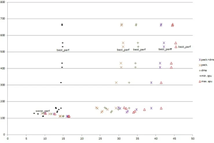
Figure 1reports the speedup of the accelerator (plot labelled min. spu) connected to the Processor Local Bus (PLB) running at 100MHz over PowerPC execution at 400MHz. 17 hardware solutions are generated in order to explore the full acceleration potential considering loop level parallelism. The corresponding acceleration on a Virtex5 device ranges from 6.96 to 14.67, which looks quite beneficial. However, if we compare these values against the maximum possible speedup where the overhead of moving data is ideally considered negligible (plot labelled max. spu in figure 1), we realize that we are far from the maximum acceleration. Especially for high performance solutions (e.g. solution labelled best_perf ), only 32% of the maximum speedup has been reached. In addition, underperforming data transfers also limits the optimisation benefits that can be expected at hardware level (loop unrolling here), as the range of acceleration is 6.96 to 14.67 while it could be of 10.26 to 46.42 ideally. A lot of the performance and processing efficiency are thus lost at the expense of data exchanges between CPU and acceleration hardware.
B. Data optimisation
Previous results pointed out the cost of moving data after fitting an HLS IP with a system bus compliant interface and the need of optimisation at this level. A first option is to use DMA. The advantage of this option is that it is a purely hardware solution almost applicable in any case and requires no change in the original application code. It does require modification of the wrapping software function to integrate DMA prior to running the accelerator, but this can be predefined in a software template (as described in section B.3). In the matrix example running on a Virtex5/PowerPC/PLB platform, DMA reduces all overheads caused by data transfers up to a factor of 7, 26. The plot labelled DMA in figure 1reports the ability of DMA to improve the global speedup significantly from 9.63 to 35.24 which represents now 78% of the maximum theoretical acceleration for the best performance solution.
A second optimisation is to make efficient use of the available bandwidth bus (here 32-bit). This is done typically by process-ing array elements of the same width of the bus. The down-side of this is that it may require more or less important code modification, thus software rewriting and simulation, hardware re-synthesis and re-verification. The following code illustrates
Fig. 1.Slice vs. speedup tradeoffs for the matrix multiplication on Virtex5/PowerPC, considering no data transfer optimisa-tion (min. spu), data packing (pack), DMA (dma), data packing with dma (pack+dma) and ideal maximum possible speedup (max. spu).
the transformation operated on the matrix function:
void matrix_mult ( unsigned i n t A[ 8 ] [ 3 2 ] , unsigned i n t B [ 8 ] [ 3 2 ] , unsigned i n t C [ 8 ] [ 3 2 ] ) { i n t i , j , k ; unsigned char _A [ 3 2 ] [ 3 2 ] , _B [ 3 2 ] [ 3 2 ] , _C [ 3 2 ] [ 3 2 ] ; / / u n p a c k i n p u t s unpack_mat (A, _A ) ; unpack_mat ( B , _B ) ; / / i n i t i a l i z a t i o n f o r ( i = 0 ; i < 3 2 ; i ++) f o r ( j = 0 ; j < 3 2 ; j ++) _C [ i ] [ j ] = 0 . ; / / m u l t i p l i c a t i o n f o r ( i = 0 ; i < 3 2 ; i ++) f o r ( k = 0 ; k < 3 2 ; k++) f o r ( j = 0 ; j < 3 2 ; j ++) _C [ i ] [ k ] += _A [ i ] [ j ] * _B [ j ] [ k ] ; / / p a c k r e s u l t s pack_mat ( _C , C ) ; }
In this version, bytes have been packed by groups of four, so the function operates now on 32-bit unsigned integers. The two operands and result arrays thus fit exactly in three 256x32-bit memories. Thanks to this, overheads caused by data transfers are reduced to a factor of 4. The corresponding global accelerator speedup resulting only from data packing ranges from 9.31 to 31.21, reaching 69% of the maximum theoretical speedup of the best solution. If we combine both DMA and data packing optimisations, data transfers are reduced 27 times and result in between 10.1 and 42.23 speedups that is, 93% of the maximum possible acceleration for the best_perf solution.
These results stress the impact on performance that inefficient data communications through the system bus produce and the consequent accelerator loss of efficiency. Mapping an IP to the system bus is a process made complex because of the variety of bus protocols, data topologies of function arguments and related optimisations that can result in very different solutions for each specific case. For instance, data packing is not applicable when the function array arguments are integers and the system bus is 32-bit wide. The challenges are thus to define a generic
Fig. 2.Generic bus wrapper interface to let a HLS generated accelerator connect an on-chip bus.
solution that can comply with different topologies of function arguments while keeping important acceleration benefits, which means allowing a set of typical data level optimisations to be applied. In addition, it should be possible to automate the bus interface generation phase in a way to fully complement HLS in the assisted generation of 100% operational IPs, removing the need for very costly additional hardware and software interface code synthesis and debug, which greatly limits HLS use and efficiency in practice. In the following, we propose an accelerator bus interface model that can comply with these constraints while keeping substantial performance benefits for a range of realistic and useful processing functions.
C. Generic bus wrapper interface
HLS tools generally produce RTL with different types of inter-face. Their interface generating process makes it possible to map the transfer of data that is implied by passing of C/C++ function arguments to various hardware resources such as wires, regis-ters, memories or streaming interfaces. Hardware acceleration is more effective when it supports atonomous processing of signif-icant data sets. Assuming function array arguments represent data sets that are likely to be fetched from external memory, a RAM based interface is thus well suited for data exchange, while leaving room for typical high-speed optimisations (DMA, data packing). Therefore a first requirement that helps the definition of a generic bus wrapper interface is to map each array argument to a distinct RAM and other arguments to registers. From there the work consists of fitting the HLS generated interface with the corresponding memory mapped resources, which process is illustrated in figure 2.
Most HLS tools support the generation of standard memory and register based interfaces. The function arguments result in all necessary signals (data / address bus, read / write) to control the corresponding RAM and registers in the output RTL. Providing access to the RAMs (C_MEM_n) requires multiplexing bus and accelerator data on a single RAM port in order to ensure bus access only when processing no longer occurs. A similar scheme is used for operand registers (REG_m). Two additional registers for device control (REG_0) and state (REG_1) are used among other to process accelerator start and done signals.
Defined this way, the bus interface model can be applied in a large number of situations and makes it a lot easier to generate both hardware and software code corresponding to the final bus compliant IP and its driver. At the moment, hardware and soft-ware wrapping steps are based on the use of templates but they
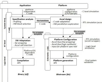
Fig. 3.Accelerator design and integration methodology.
could be automated by the development of proper code gener-ation tools. In the following, we describe the complete design flow underlying accelerator development with the proposed bus interface model.
4. ACCELERATION METHODOLOGY
A. Overview
Elaborate set of tools is available to permit the full prototyping of complex heterogeneous System-on-Chips like multiprocessor systems embedded with standard programmable logic blocks or recent FPGA-based platforms. The methodology used here is built around relevant tools involved in this kind of develop-ment. Xilinx provides the prototyping environment to bring a proof of concept on fully operating applications. ML605 and ML507 evaluation boards have been used for this purpose with an Embedded Development Kit 13.3 Release for all related de-velopments. In addition, High-Level Synthesis is considered as we aim to automate the design flow as much as possible. At the time of this work, a Mentor Graphics Catapult C Synthesis 2009a Release has been used, in association with Precision RTL Synthesis for lower level synthesis. Verification and simulation steps are based on C code for software and Mentor Modelsim for hardware (see section C). The resulting design flow is illus-trated in figure 3. Top-to-bottom steps represent application and architecture development at different levels (System, Reg-ister transfers, Logic), while transverse verification processes are present to every life cycle stage of the system to check the correctness of transformations against the top C reference model. At the system level, the design entry point is an executable functional description written in standard ANSI C or C++. The first step is to identify critical pieces of code that can best benefit from hardware acceleration. Since not all functions will end up going faster in hardware than in software, a first level of exploration occurs here which is done typically using perfor-mance analysis tools. For the time consumming pieces of code highlighted, a qualitative inspection is necessay to evaluate the suitability of these functions to hardware implementation and HLS. Relevant inputs to HLS are data intensive workloads and kernels of computations like those present in multimedia ap-plications (image and video processing), scientific computing and digital signal processing (filters, transforms) and regular
processing loops. As pointed out in section 3, narrow focus on the processing aspect is not enough since performance bottle-necks lie in the communication of data between memory and the IP. This has also to be taken in consideration when selecting potential hardware functions. Therefore inspecting their po-tential acceleration considering data communication overheads gives a better picture of the full application speedup. When an acceptable global speedup corresponding to a set of hardware functions is found, accelerator related development takes place. It starts from a C code and ends up with a dedicated accelerator that can be connected to the system bus. This process repre-sents the critical part of the development effort, it is described in greater details in section B.
HLS is considered here for faster automated development. Code rewriting will occur in most cases before proceeding to HLS, mainly for two reasons. First, RTL synthesis tools are not able to support all features of the C language. Second, HLS gen-erated hardware must comply with the data topology defined previously. These points are further detailed in section B. When a C function for hardware acceleration is HLS and interface data compliant, the whole application C code is re-validated against the reference code. Then, automatically correct by construction RTL can be produced. Resource and loop parallelism are usu-ally examined at this level leading to the exploration of various tradeoffs in terms of area, power and performance.
From a RTL solution available at this stage, the accelerator interface needs to be refined into a memory mapped interface that will let it connect to the on-chip system bus. Wrapping is based on the generic model proposed in section Cand the process is exposed in detail in section B.2. Upon completion, the wrapped accelerator is generated by logic synthesis resulting into an operational hardware module which is fully compliant with the target bus protocol. On the software part, a driver for the accelerator must also be produced. The topology of func-tion arguments underlying the generic bus wrapper interface allows the definition of a generalizable driver template for the IPs, which is further discussed in section B.3. In addition, the original application code must be adapted to replace the original software functions by calls to their corresponding accelerators, but also to setup data packing / unpacking before and after processing. At the end, we get a platform dependent C code of the whole application that can be compiled and run on the target.
At this step, all the necessary material is available to gen-erate the full hardware and software code. Platform depen-dent C code can be compiled to a binary for hardware / soft-ware co-execution of the accelerated application. A gate level netlist is produced by logic synthesis (Mentor Precision) from the wrapped RTL IP. The resulting bus compliant hardware is then used in Xilinx Platform Studio (XPS) to specify the full platform, and XPS handles the generation of all related low level files (bitstream and binaries). The full application is therefore executed and verified on real prototypes, based on Xilinx evalu-ation boards and associated debug tools. The following section focusses more specifically on the development of hardware ac-celerators.
B. Accelerator development
There are three main steps involved in accelerator develop-ment. The first one is accelerator design, here using High-Level Synthesis and associated exploration features. Then the result-ing RTL is wrapped as an IP to be connected to the system bus,
and finally the initial function is replaced by a software wrapper function that calls the accelerator. Each step is further detailed in the following.
B.1. HLS and data compliance
This section focuses on the process of writing input C code complying with both HLS and interface data constraints.
The need to rewrite code prior to RTL synthesis comes firstly from the use of a high-level software language for the input functions. There are indeed sometimes no trivial correspon-dance between software specific constructs and hardware im-plementation. A typical example is that of video inter-frame processing which requires a large frame buffer that can only be implemented in external memory. Such functionality is usually specified using pointers to the pixel frame buffer that HLS is not able to process, because it depends on external elements over which these tools have no control (external memory, memory controller, system bus). This implies to think the software func-tion data with in mind the hardware constraints of moving data from external to local accelerator’s memories. It often results in a significant modification of the original application code which is impossible to automate as the transformations depend on each individual case, may be complex and impact more or less the whole code. In extreme cases, complete application re-design is needed to cope with HLS and memory constraints (e.g. removal of functions processing frame buffer data in external memory via pointers).
Secondly, hardware function arguments must cope with the interface data constraints defined previously to ease the gen-eration of a bus compliant interface. In that matter, input and output data must be explicitly expressed in C function parame-ters, preferably using arrays and variables to provide a natural correspondance with hardware in terms of memories and regis-ters.
Finally, previous study on matrix multiplication has stressed the need for data transfer optimisation. Typical techniques be-ing data packbe-ing and DMA, function arguments must then be modified accordingly. In particular, packing and unpacking techniques can lead to more or less modifications of the origi-nal function and attention must be paid to packing/unpacking overheads against acceleration benefits.
The corresponding requirements on function interface data are summarized in the following:
• Input and output data are explicitly expressed in function parameters as standard arrays and variables that can be mapped to memory and register resources. Processing of global shared variables must be removed. Pointers are supported by some tools provided their use is restricted to inner function processing.
• All array parameters exploit data packing/unpacking tech-niques (when applicable) to benefit from the full bandwidth bus and reduce further the cost of moving data.
• In terms of HLS tool setup, each function array argument is set to a distinc RAM and each function scalar (non array) argument is set to a distinct register. HLS will then produce all necessary signals for the corresponding resources in the interface of the function RTL module. For instance, Catapult options must be set to map each I/O array to a distinct RAM single port, and it will generate a data and address bus, R/W signals and enables in the interface of the function RTL module.
• There may be other constraints resulting from other tools in the design flow. For example, Xilinx Platform Studio has a maximum memory and register capacity for user logic resources. Thus the number of function array arguments must not exceed the capacity of eight 256x32-bit single port RAMs and the number of function scalar arguments must not exceed the capacity of 4096 registers.
• Additionally, the HLS tool is set to provide start and done signals in the interface of the function RTL module. These signals are further processed with two dedicated registers in the bus interface template.
From a function C code meeting previous guidelines, HLS can generate a RTL module compatible with the bus wrapper inter-face template. Next section describes the hardware wrapping process.
B.2. Hardware wrapping
At this point, a RTL description satisfying all interface require-ments is available. As exposed in section C, the bus wrapper interface model encompasses registers, memories and mecha-nisms to let their control either by the bus or by the accelerator. As a matter of fact, previous guidelines ensured that the RTL in-terface generated by HLS is exactly compatible with the signals needed to drive memory mapped resources of the bus wrapper interface. Connections are thus straightforward:
• RAM signals from the accelerator are mapped to the cor-responding RAM single port signals in the bus wrapper interface.
• Register signals from the accelerator are mapped to the corresponding register signals in the bus wrapper interface.
• Two additional registers act as control and status registers. They are used primarily to process start and done bits in the respective registers.
A mechanism is employed to set automatically which of the accelerator or the system bus will master the memories and registers. The control signals from the bus and IP connect to mul-tiplexers under the control of a busy signal (figure 2). The busy signal is set for the entire processing duration, from start to done signal assertions. When active, the accelerator drives memories and registers, when inactive, the system bus drives memories and registers. This ensures conflict free data accesses between the accelerator and other devices (CPU, DMA). This mechanism is implemented in the bus wrapper interface template, so the user just has to insert the HLS generated RTL providing a few ad-justments on the memory and register signals (number, bitwidth, mapping). In practice, completing this is a matter of a hours depending on the topology of the function arguments. Two bus wrapper interface templates are currently available to support PLB and AXI protocols.
B.3. Software wrapping
At this point, the application code has to be modified such that the functions implemented in hardware can be replaced by wrapper functions that call the accelerators instead of do-ing computations in software. Additionally, extra code may be needed to setup array function arguments before and after accelerator processing when data packing techniques are used. Driver functions have thus to be developped for proper acceler-ation call and here again, the bus wrapper interface model helps to define a generic template also extending its applicability in a
maximum number of cases. Since a driver function will have the same prototype as its corresponding original software function, we refer to this step as software wrapping. The wrapper func-tion template performs driver necessary acfunc-tions in the following order:
1. Sets DMA to write each input array to its corresponding RAM.
2. Writes each input scalar to its corresponding register.
3. Sets the start bit in the control register (asserting start sig-nal).
4. Polls the status register for hardware completion (based on done signal value).
5. Reads each output scalar from its corresponding register.
6. Sets DMA to read each output array from its corresponding RAM.
As for hardware wrapping, software wrapping is manual at the moment. This process, however much less complex, can be completed in a matter of minutes and could be automated easily.
C. Verification and simulation
Verification takes significant effort in hardware design cycles, it is therefore essential to be able to check the correctness of the transformations involved at each level. The right side of figure
3points out the key steps where verification can be applied in the design flow. Reference results are provided by the top level application C code. Transformations of this reference code can be simulated at each phase of accelerator development: HLS RTL, wrapped RTL and logic level IP.
Simulations of HLS and logic synthesis outputs are not nec-essarily mandatory as synthesis tools are expected to provide correct by construction results. However, errors can arise in practice when designs are quite complex, so hardware simu-lations must be provided at these levels. Hardware wrapping verification is necessary as well to check the correctness of an accelerator when communicating data across the bus. Three levels of hardware simulations are thus provided with stan-dard HDL simulators (ModelSim) for which specific testbench templates have been defined. The templates consist of HDL code instantiating a function block and connecting its top level signals to stimulus-dependent signals. These signals are pre-set to send datapre-sets to the accelerator’s memories, write scalar operand data into registers and assert the start signal. After an ajustable amount of time (depending on the assertion of the done signal), signals are set to read the content of result memories and registers.
For the hardware wrapping step in particular, these templates relieve the user from knowing precisely the bus protocol and generating complex bus related signals. The user is only left with the task of setting the values of stimuli signals to the design. These hardware simulation templates allow to check that the outputs of accelerators match the original C function results. Final system validation occurs at the end of the flow by compar-ing the final platform dependent C code includcompar-ing accelerator invocation against the results of the application reference code.
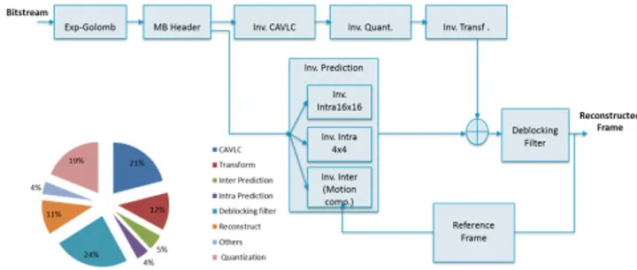
Fig. 4.H.264/AVC decoder block diagram and profiling.
5. APPLICATION STUDY AND RESULTS
A. H.264/AVC decoder
In this section, we present experiments and results of the pro-posed acceleration methodology on a real-life application exam-ple. The principal objective is to verify that accelerator speedups are still relevant after adding bus interface logic. Incidentally, the wide range of data processing and transfer characteristics reveals conditions impacting the actual efficiency of hardware accelera-tion and optimisaaccelera-tion (considering HLS loop unrolling), espe-cially when fitted with a bus compliant interface. The application which is considered for this validation study is a H.264/AVC profile video decoder. This example is also instructive to set high processing functions exposing various coding styles and data structures against HLS implementation.
The H.264 decoder used corresponds to the block diagram of figure 4which is a version derived from the ITU-T refer-ence code [24] to comply with hardware design constraints and HLS. From the original C++ code, a profiling step identifies four main functionalities for acceleration that are in order of impor-tance, the deblocking filter (24%), the inverse context-adaptive variable-length coding (Inv. CAVLC 21%), the inverse quantiza-tion (Inv. Quant. 19%) and the inverse integer transform (Inv. Transf. 12%). To achieve better results, we have merged the inverse quantization and integer transform into a single block. It might be noted here that CAVLC was not added to this block be-cause Catapult could not handle the complexity of the resulting C code. Therefore, this results in three potential hardware func-tions representing 76% of the total processing time, indicating a maximum possible acceleration of 4, 17 for the entire decoder.
The deblocking filter, inverse CAVLC, and inverse quanti-zation and transform block constitute the entry points to the accelerator design step of figure 3. Two Xilinx evaluation boards (ML507 and ML605) are used for implementation and test. The ML507 integrates a Virtex5 device and a PowerPC hard IP core that can run at 400MHz, while the ML605 lets the possibility to deal with two types of bus interfaces, PLB and AXI in a Vir-tex6 device with MicroBlaze soft IPs. The three afore-mentioned functions have been designed each in two versions to consider both PLB and AXI protocols, with the corresponding accelera-tors operating at the frequency of the system bus which is set to 100MHz in all cases. In these conditions, we have measured the accelerator speedups against each reference software code executed on a 400MHz PowerPC for the Virtex5 and 100MHz MicroBlaze for the Virtex6. The following sections analyse the ac-celeration results and the relevance of the bus wrapper interface for the hardware blocks identified.
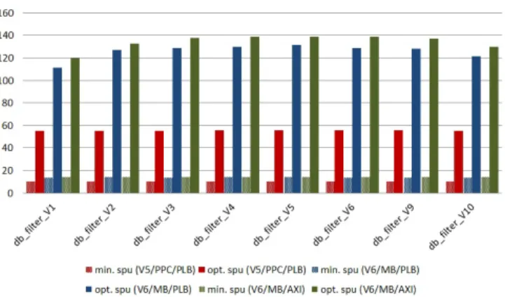
Fig. 5.Speedup improvement for the deblocking filter on Vir-tex5/PowerPC (PLB) and Virtex6/MicroBlaze (PLB, AXI).
Fig. 6.Slice vs. speedup tradeoffs for the deblocking filter on Virtex5/PowerPC (PLB) and Virtex6/MicroBlaze (PLB, AXI).
B. Deblocking Filter
The deblocking filter is a post-processing technique used to im-prove the visual quality of decoded pictures by reducing the edge effects resulting from macroblock processing. It runs on the edges of each macroblock, in both horizontal and vertical directions and for both luminance and chominance pixels. Each edge is assigned a boundary strength which defines the level of pixel correction to apply, stronger levels of filtering are assigned where there is likely to be more distortion. These operations are reflected into six pixel processing loops that can efficiently ben-efit from loop unrolling optimisations. These optimisations do not require any source code modifications, but only setting op-tions in the HLS tool. In addition, as the RTL generated exposes the same top level interface, the exact same hardware wrapper can be re-used. Thanks to this, loop parallelism exploration is easy to apply as it only requires iterations of HLS, logic synthesis and platform generation which are fully automated steps.
Deblocking filter processing is a good fit to hardware accel-eration requirements and yields good results. Plots labelled min. spu in figure 5reports hardware acceleration over soft-ware execution using a basic bus interface without specific data optimisation, up to 14 for Virtex6/MicroBlaze and 10 for Vir-tex5/PowerPC. Figure 5also reflects the improvements of the bus wrapper interface (plots labelled opt. spu), with values up to 138 for Virtex6/MicroBlaze and 55 for Virtex5/PowerPC. Comparative speedups are increased on average by 9.3 for Vir-tex6/MicroBlaze and 5.3 for Virtex5/PowerPC.
A total of eight solutions have been explored to check the im-pacts of accelerator level optimisations after bus wrapping (loop unrolling in this case). Eight cost-performance tradeoffs are re-ported in figure 6with respect to Virtex6/MicroBlaze (PLB, AXI) and Virtex5/PowerPC (PLB) execution. Relatively few speedup profits can be observed despite the sensitive increase of FPGA resources (Slices). This is less noticeable for MicroBlaze. As it is a lower performance processor, the ratio between software and hardware execution time is increased and this amplifies the differences between different hardware performances. However, even for the Virtex6/MicroBlaze platform, increasing the FPGA occupation by 2.7 only results in performance improvements of 14.4%. We can also observe a clear limit on the maximum achievable speedup for both platforms. This comes from the incompressible quantity of data movement and from the bus bandwidth which restrict the maximum possible speedup. This is especially visible on Virtex5/PowerPC because the possible speedups and range of acceleration are noticeably lower com-pared to MicroBlaze, due to better processor performance. The overhead caused by data transfers is also responsible for limiting the efficiency of loop unrolling, and by extension of accelerator level optimisations.
C. Quantization and Transform
In H.264 encoding, each residual macroblock, i.e. the difference between the predicted macroblock and the actual macroblock, is transformed and quantized prior to entropy coding. The process is reversed at the decoder level and the transform coefficients are rescaled (inverse quantized) and inverse transformed prior to frame reconstruction. The transform is a scaled approximation of the Discrete Cosine Transform to support integer arithmetic that can better benefit from optimising hardware. Quantization is thus used to reduce a range of transform coefficient values to a single quantum value which results in a more compressible stream. Quantization and integer transform expose properties that have been deliberately designed to be well suited to imple-mentation in hardware. But compared to the deblocking filter, it comes with more instruction or operation level parallelism than loop level parallelism.
Fig. 7.Speedup improvement for the inverse quantization and transform block on Virtex5/PowerPC (PLB) and Vir-tex6/MicroBlaze (PLB, AXI).
Acceleration results of nine solutions report maximum speedups around 8 for Virtex6/MicroBlaze and 5 for Vir-tex5/PowerPC for a basic bus interface implementation (plots labelled min. spu in figure 7), and up to 142 and only 13 (respec-tively) using the optimised bus wrapper interface (plots labelled
Fig. 8.Slice vs. speedup tradeoffs for the inverse quantiza-tion and transform block on Virtex5/PowerPC (PLB) and Vir-tex6/MicroBlaze (PLB, AXI).
opt. spu). Apart from the effect of frequency, the acceleration difference between Virtex6/MicroBlaze and Virtex5/PowerPC is further accentuated because the MicroBlaze is also less efficient at exploiting instruction parallelism than PowerPC (dual-issue, superscalar architecture). Therefore, the acceleration over pro-cessor execution looks fairly better due to MicroBlaze relative low performance at processing inverse transform and quantize functions. In these conditions, the improvements in accelerator speedups resulting from the bus wrapper interface are 15.9 for Virtex6/MicroBlaze and 2.3 for Virtex5/PowerPC in average. Although the improvements seem less for Virtex5/PowerPC, again due to better PowerPC processing efficiency for this piece of code, the benefits still outperform non optimised bus mapping by more than two orders of magnitude.
A total of nine cost-performance tradeoffs are reported in fig-ure 8for Virtex6/MicroBlaze (PLB, AXI) and Virtex5/PowerPC (PLB) implementations. Here again, exploring loop parallelism results in limited performance improvements, especially for so-lutions with relative low speedup levels (e.g. Virtex5/PowerPC). As for the deblocking filter, it is also visible that the maximum acceleration is bound by data transfers on the bus which effect is stressed by higher processor performance (PowerPC). Data transfers also impact the benefits of accelerator level optimisa-tions that reflect poorly on practical speedups.
D. Context-adaptive variable-length coding (CAVLC)
Context-adaptive variable-length coding (CAVLC) is an entropy coding technique applied at the output of the quantization of transform coefficient values. It consists of a loseless adaptive compression algorithm where a symbol (transform coefficient) is assigned a code of variable length depending on its probability of occurence. As sequential CAVLC decoding algorithms com-pare bit sequences of different lengths, they consist mainly of conditional statements, bit level operations with relatively few parallelism. Unlike two previous examples, it is a more difficult exercise to reach efficient dedicated hardware implementations of CAVLC processing using HLS. HLS performs well at extract-ing operation and loop level parallelism but more poorly at bit-wise and conditional processing.
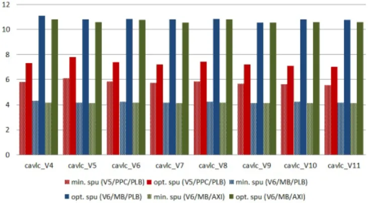
As expected, the benefits of hardware acceleration reported in figure 9are lower, however speedup values are still relevant: until 4 for Virtex6/MicroBlaze and 6 for Virtex5/PowerPC for a basic interface (plots labelled min. spu), up to 11 and 7 (respec-tively) for the optimised bus interface (plots labelled opt. spu).
Fig. 9.Speedup improvement for the inverse CAVLC on Vir-tex5/PowerPC (PLB) and Virtex6/MicroBlaze (PLB, AXI).
In this case, less effective HLS solutions reflect in weaker accel-eration results. Comparison of the bus wrapping scheme over a non optimised interface (opt. spu vs. min. spu) shows that there is an improvement in all cases, which is of 2.6 for MicroBlaze and 1.3 for PowerPC in average on the respective accelerators.
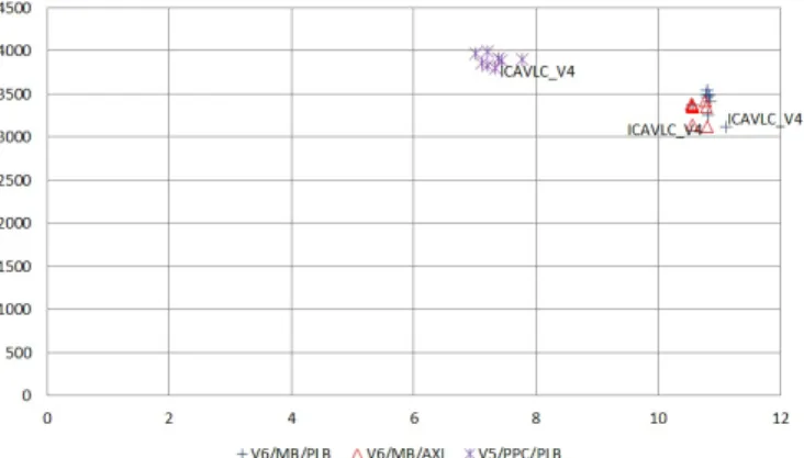
For this function, the lack of inherent parallelism that can be exploited by HLS is clearly visible in the results of loop par-allelism exploration. Figure 10shows that there is almost no difference between the eight solutions derived from loop un-rolling. An important characteristic of CAVLC to consider here is that the amount of data processed is significantly less than for both previous functions (1088 bytes for deblocking filter, 1632 bytes for inverse quantization and transform and 148 bytes for CAVLC). Relative speedup limitation of this function is thus coherent with asumptions of section Cdefining an accelator interface for data-intensive functions. If the quantity of data processing is reduced, the benefits of hardware acceleration de-clines because the acceleration potential generally grows with the volume of data operations. This consideration impacts the effectiveness of hardware level optimisations as well, which are proving to be quite limited in this case.
E. H.264/AVC decoder global acceleration
Global accelerations of the full H.264/AVC decoder considering previous accelerators have been computed and reported in ta-ble 1. For each hardware function, we have selected the fastest and the slowest solution from the different implementations explored with HLS, except for CAVLC where there is only one Pareto optimal solution. We have then combined these hard-ware implementations (considering also the remaining softhard-ware functions) in order to highlight maximum and minimum perfor-mance solutions at the full Hw/Sw application level. The range of performance is computed for both basic and optimised bus wrapper interfaces, and for Virtex6/MicroBlaze (PLB, AXI) and Virtex5/PowerPC (PLB) platforms.
The bus wrapper interface significantly improves the overall application execution with global speedups around 3.8 (MicroB-laze) and 3.3 (PowerPC), performing better than a basic interface (2.7 - 2.8) and better approaching the maximum theoretical ac-celeration of 4, 17. Compared to previous results on individual accelerators, we observe very little difference between minimum and maximum performance of the global application, which reflects even lesser benefit of loop paralellism exploration. Con-sidering a full Hw/Sw implementation thus reduces further the already limited profits of accelerator related optimisations
Fig. 10.Slice vs. speedup tradeoffs for the inverse CAVLC on Virtex5/PowerPC (PLB) and Virtex6/MicroBlaze (PLB, AXI).
Table 1.H.264/AVC decoder global acceleration
H.264/AVC decoder
max perf solution min perf solution basic bus wrap. int. speedup slices speedup slices
V5/PPC/PLB 2.77 6386 2.77 4846
V6/MB/PLB 2.87 6386 2.85 4846
V6/MB/AXI 2.87 6372 2,87 4860
max perf solution min perf solution opt. bus wrap. int. speedup slices speedup slices
V5/PPC/PLB 3.35 6386 3.27 4846
V6/MB/PLB 3.8 6386 3.79 4846
V6/MB/AXI 3.8 6372 3.79 4860
(excluding data transfers) and this effect naturally grows with the share of software execution.
6. CONCLUSION AND PERSPECTIVES
This work described a method to improve the automation of re-configurable hardware acceleration, based in particular on code transformations at the interface level to cope with practical bus interface generation constraints. The proposed approach has been proven to be fully operational while reducing significantly the design effort. Results have shown the ability of the pro-posed data argument topology and the associated bus wrapper interface to provide accelerator performances approaching the maximum global speedup in different conditions, and consid-ering realistic processing examples, different bus protocols and performance class of processors.
This methodology already had contributions in the context of several research efforts. It has been used in a collaborative platform project for the modelling of power consumption in heterogeneous multicore systems [25], in which it served for the definition of high level power models of reconfigurable accel-erators derived from actual power measures of HLS generated designs [26]. The acceleration methodology is also very helpful for the exploitation of dynamic and partial reconfiguration. It has been used to quickly provide realistic hardware implemen-tations and characteristics whithout which design space analysis would not not be possible, for example to explore the sizing
of reconfigurable regions [27][28] or to provide reliable energy estimations of dynamically reconfigurable mappings [29]. Fi-nally, an important issue in the perspective of heterogeneous, accelerator based multicore systems is to address the runtime management of concurrent hardware and software tasks, to fully exploit the potential of hardware acceleration with dynamic re-configuration in terms of energy and power related constraints.
ACKNOWLEDGMENTS
The authors would like to thank the Centre of Integrated Mi-croelectronics of Provence-Alpes-Côte d’Azur [1] for providing CAD software and support in the use of many advanced design tools.
REFERENCES
1. CIM PACA, Centre of Integrated Microelectronics of Provence-Alps-Côte d’Azur, France, www.arcsis.org 2. Cray Inc., Cray XR Reconfigurable Processing Blade,
www.cray.com
3. Intel Corp., Intel QuickAssist Technology, www.intel.com 4. Celoxica Accelerated Trading Solutions, www.celoxica.com 5. J. M. Rabaey, Reconfigurable processing: The solution to
low-power programmable DSP, in Proc. 1997 IEEE Intl. Conf. on Acoustics, Speech, and Signal Processing (ICASSP ’97), Vol. 1, Los Alamitos, CA: IEEE Computer Society Press, 1997, pp. 275-278.
6. G.J.M. Smit, A.B.J. Kokkeler, P.T. Wolkotte, P.K.F. Hölzen-spies, M.D. van de Burgwal, and P.M. Heysters, The Chameleon Architecture for Streaming DSP Applications, EURASIP Journal on Embedded Systems, 2007 . p. 78082. ISSN 1687-3955
7. G. Lu , Hartej Singh , M.H. Lee , N. Bagherzadeh , F. Kurdahi , E. M. C. Filho, The MorphoSys Parallel Reconfigurable System, Proceedings of 5th Euro-Par Conference, Toulouse, France, Sep 99.
8. S. Pillement, O. Sentieys, and R. David, DART: a functional-level reconfigurable architecture for high energy efficiency, EURASIP Journal on Embedded Systems, Reconfigurable Computing and Hardware/Software Codesign, Volume 2008, January 2008.
9. A. Grasset, P. Millet, P. Bonnot, S. Yehia, W. Putzke-Roeming, F. Campi, A. Rosti, M. Huebner, N. S. Voros and D. Rossi, H. Sahlbach, R. Ernst, The MORPHEUS Heterogeneous Dynam-ically Reconfigurable Platform, Special Issue on High Perfor-mance and Embedded Architecture and Compilation, Inter-national Journal of Parallel Programming, Volume 39, Num-ber 3, 328-356,
10. PACT XPP Technologies, www.pactxpp.com 11. Recore Systems, www.recoresystems.com
12. M.D. van de Burgwal, P.T. Wolkotte, and G.J.M. Smit, Non-Power-of-Two FFTs: Exploring the Flexibility of the Montium TP, International Journal of Reconfigurable Computing: Vol-ume 2009, Article ID 67804.
13. DRC Coprocessor, www.drccomputer.com
14. T.J. Callahan, J.R. Hauser, J. Wawrzynek, The Garp architec-ture and C compile, IEEE Computer 33 (4) (2000) 62-69. 15. D. Pellerin and S. Thibault, Practical FPGA Programming
in C, Prentice Hall, ISBN: 0131543180, 2010.
16. Altera Corporation, Automated Generation of Hardware Accelerators With Direct Memory Access From ANSI/ISO Standard C Functions, White paper, www.altera.com, may 2006.
17. D. Burnette, An ESL methodology for functional verifica-tion between untimed C++ and RTL using SystemC, Mentor Graphics, 2008
18. J. Sanguinetti and D. Pursley, High-level modelling and Hardware Implementation with General Purpose Languages and High-level Synthesis, Ninth IEEE/DATC Electronic De-sign Processes Workshop, April 2002.
19. J. Cong, B. Liu, S. Neuendorffer, J. Noguera, K. Vissers and Z. Zhang, High-Level Synthesis for FPGAs: From Prototyp-ing to Deployment, IEEE Transactions on Computer-Aided Design of Integrated Circuits and Systems, Volume 30, Num-ber 4, pp. 473-491, April 2011.
20. P. Coussy, D.D. Gajski, M. Meredith, A. Takach, An introduc-tion to high-level synthesis. IEEE Design & Test of Computers 26(4):8-17, 2009.
21. W. Meeus, K. Van Beeck, T. Goedemé, J. Meel, D. Stroobandt, An overview of today’s high-level synthesis tools, Design Automation for Embedded Systems, August 2012.
22. A. Fraboulet and T. Risset, Master Interface for On-chip Hardware Accelerator Burst Communications, Journal of VLSI Signal Processing Systems, Volume 49 Issue 1, pp. 73-85, October 2007.
23. J.P. Diguet, G. Gogniat, J.L. Philippe, Y. Le Moullec, S. Bilavarn, C. Gamrat; K. Ben Chehida, M. Auguin, X. Fornari and P. Kajfasz, EPICURE: A partitioning and co-design frame-work for reconfigurable computing, Journal of Microproces-sors and Microsystems, Special Issue on FPGA’s, Edited by Morris Chang and Dan Lo, Volume 30, Issue 6, pp. 367-387, 2006.
24. ISO/IEC 14496-10, Advanced Video Coding for Generic Au-diovisual Services, ITU-T Recommendation H.264, Version 4, 2005.
25. Open-PEOPLE - Open-Power and Energy optimisation PLatform and Estimator, http://www.open-people.fr/. 26. R. Bonamy, D. Chillet, O. Sentieys and S. Bilavarn,
Paral-lelism Level Impact on Energy Consumption in Reconfig-urable Devices, International Workshop on Highly-Efficient Accelerators and Reconfigurable Technologies (HEART 2011), London, United Kingdom, June 2-3, 2011.
27. FoRTReSS - Flow for Reconfigurable archiTectures in Real-time SystemS, https://sites.google.com/site/fortressdesignsuite/. 28. F. Duhem, F. Muller, W. Aubry, B. Le Gal, D. Négru, and
P. Lorenzini. Design space exploration for partially recon-figurable architectures in real-time systems. under revison, Journal of Systems Architecture (JSA), Elsevier.
29. R. Bonamy, D. Chillet, S. Bilavarn and O. Sentieys, Power Consumption Model for Partial and Dynamic Reconfigu-ration, 2012 International Conference on ReConFigurable Computing and FPGAs, ReConFig 2012, December 5-7, 2012, Cancun, Mexico.