ÉCOLE DE TECHNOLOGIE SUPÉRIEURE UNIVERSITÉ DU QUÉBEC
THESIS PRESENTED TO
ÉCOLE DE TECHNOLOGIE SUPÉRIEURE
IN PARTIAL FULFILLMENT OF THE REQUIREMENTS FOR THE DEGREE OF DOCTOR OF PHILOSOPHY
Ph. D.
BY
Sébastien ADAM
SYSTEMATIC INFERENCE OF THE CONTEXT OF UTILIZATION OF THE DESIGN KNOWLEDGE BY USING A REFERENCE MODEL
MONTREAL, JUNE 07, 2016
This Creative Commons licence allows readers to download this work and share it with others as long as the author is credited. The content of this work may not be modified in any way or used commercially.
THIS THESIS HAS BEEN EVALUATED BY THE FOLLOWING BOARD OF EXAMINERS
Mr. Alain Abran, Thesis Supervisor
Department of LOG/TI at École de technologie supérieure
Mrs. Ghizlane El Boussaidi, Thesis Co-supervisor
Department of LOG/TI at École de technologie supérieure
Mrs. Catherine Laporte, President of the jury École de technologie supérieure
Mr. Christian Desrosiers, Chair, Board of Examiners Department of LOG/TI at École de technologie supérieure
Mr. Hamid Mcheick, External Evaluator Université du Québec à Chicoutimi - UQAC
THIS THESIS WAS PRESENTED AND DEFENDED
IN THE PRESENCE OF A BOARD OF EXAMINERS AND THE PUBLIC ON MAY 12, 2016
ACKNOWLEDGMENTS
I would like to thank my family and friends for the support they provided me through my doctoral project. In particular, I acknowledge my wife for her love, encouragement, efforts, assistance, and sacrifices.
I would like to express my gratitude to my supervisors, the professors Alain Abran and Ghizlane El Boussaidi, for their expertise and understanding that added to my doctoral experience. A very special thanks to Alain for his assistance in writing reports, articles, and this thesis, and for inspiring me kindness, promptness, and motivation over many ways. A very special thanks to Ghizlane for his assistance in defining the focus of my project. I thank both of you for our exchanges that enriched my doctoral experience.
SYSTEMATIC INFERENCE OF THE CONTEXT OF UTILIZATION OF THE DESIGN KNOWLEDGE BY USING A REFERENCE MODEL
Sébastien ADAM
ABSTRACT
Software engineering is concerned with systematic procedures for obtaining software that meets the customer’s expectations. Taking into account the impacts of the software design artifacts when designing the architecture of a software system is critical, but it remains a major challenge. The contribution of the architecture to achieve or not targeted objectives results from the utilization in the architecture and in the detailed design of an appropriate set of software design artifacts (SDAs) such as styles, tactics, and design patterns. The styles and design patterns organize the design decisions, and the tactics are building blocks of these styles and patterns. The software designer is responsible for applying tactics, patterns, and styles that best achieve the targeted objectives. This requires understanding what objectives are affected by the styles, patterns, and tactics applied, identifying which styles and patterns best support a set of tactics, and discerning which set of design decisions produces the best balance across the targeted objectives. The software designers encounter at least three problems when discerning the design context and measuring the effects of a style, a design pattern, or a tactic on a set of objectives:
1. the representation schemes usually used to describe the SDAs force the software designers to extract from textual descriptions the finer-grained decisions and the related explications about how they impact the objectives;
2. the explanations of these impacts are described in terms of characteristics of quality, and they are not precisely detailed and supported with contextual design rationale; 3. the effects of a design decision are not quantified but merely discussed textually
making it hard to evaluate which decision is better than others in a particular context. This research project provides a reference model of software design artifacts for describing the styles, patterns, and tactics using a set of software design artifacts and arguments. This reference model and the related techniques will support designers to systematically analyze styles, tactics, and design patterns for inferring the order of treatment of the related issues from given sets of software design artifacts and contextualized arguments.
Keywords: Design knowledge management, Design artifact, Reference model, and Design
INFÉRENCE SYSTÉMATIQUE DU CONTEXTE D’UTILISATION DES
CONNAISSANCES DE CONCEPTION À L’AIDE D’UN MODÈLE DE RÉFÉRENCE
Sébastien ADAM
RÉSUMÉ
La définition d’activités systématiques pour développer des logiciels satisfaisants les attentes des parties prenantes est une préoccupation du génie logiciel. Concevoir l’architecture et la conception détaillée d’un logiciel est une activité critique. Atteindre les objectifs ciblés résulte de l'utilisation d'un ensemble approprié d’artéfacts de conception tels que les styles, les tactiques et les patrons. Les styles et les patrons organisent les décisions de conception. Les tactiques sont des blocs de construction des styles et des patrons. Le concepteur du logiciel est responsable d’appliquer les styles, les patrons et les tactiques pour permettre d'atteindre au mieux les objectifs ciblés. Pour satisfaire les parties prenantes, le concepteur doit:
• comprendre les objectifs affectés par les styles, les patrons et les tactiques appliqués; • identifier les styles et les patrons pour supporter au mieux l’ensemble des tactiques; • prendre des décisions pour produire le meilleur équilibre entre les objectifs ciblés; et • comprendre les effets des artéfacts de conceptions utilisés.
Le concepteur du logiciel a quelques préoccupations lors de la mesure des effets des styles, des patrons et des tactiques sur un ensemble d'objectifs ciblés, incluant:
• les schémas de représentations textuelles ou graphiques généralement utilisés pour décrire les styles, les patrons et les tactiques obligent le concepteur à extraire les décisions de conception et les connaissances de leurs effets sur le logiciel;
• les effets sont décrits en termes de caractéristiques de qualité et ne sont pas précisément détaillés et soutenus par des explications contextuelles; et
• les effets ne sont pas quantifiés, ce qui rend difficile d'évaluer quelle décision est mieux qu’une autre dans un contexte particulier.
Ce projet de recherche propose un modèle de référence pour décrire les styles, les patrons et les tactiques à l’aide d’un ensemble d’artéfacts de conception et d’arguments. Le modèle de référence et les techniques connexes sont proposés pour soutenir le concepteur lors de l’analyse des styles, des patrons et des tactiques utilisés dans un contexte particulier. La méthodologie proposée permet d’inférer à partir d’un ensemble d’arguments contextualisés l'ordre de traitement des problèmes liés à l’utilisation des artéfacts de conception.
Mots-clés: gestion des connaissances de conception, artéfact de conception, modèle de
TABLE OF CONTENTS
Page
INTRODUCTION ...1
Software Engineering and Software Architecture ...1
The Design Knowledge (DK) Base ...1
The Software Designer Role ...3
Research Problem ...3
Research Question, Hypothesis, and Approach ...5
Research Goal, Research Sub-Goals and Research Objectives ...5
Originality and Expected Benefits ...8
Research Methodology ...9
Phase 1 – Collect Data ... 10
Phase 2 – Develop the Reference Model ... 10
Phase 3 – Develop techniques ... 11
Validation of Research Results ...11
Validation Activities ... 12
Thesis Organization ...13
CHAPTER 1 LITERATURE REVIEW ...15
1.1 Basic Concepts ...15
1.1.1 Software Development Approach ... 15
1.1.2 Software Architecture Design and Detailed Design ... 16
1.1.3 Software Architecture ... 17
1.1.4 Architectural Style and Tactic ... 18
1.1.5 Design Pattern ... 20
1.1.6 Characteristics of quality ... 22
1.2 Effects of Styles, Design Patterns, and Tactics on the Software Quality ...24
1.3 Approaches for Representing Tactics, Design Patterns and Styles ...26
1.3.1 Representation Schemes for Tactics ... 26
1.3.1.1 Catalog of Architectural Tactics ... 27
1.3.1.2 Feature and UML-Based Modeling ... 28
1.3.1.3 Formal Specifications ... 29
1.3.2 Representation Schemes for Design Patterns and Styles ... 29
1.3.2.1 GOF-Based Template for Design Patterns ... 29
1.3.2.2 Catalogue of Styles ... 30
1.3.2.3 Architecture Definition Languages (ADL) ... 31
1.3.2.4 Formal Representations of Styles ... 32
1.3.2.5 UML-Based Representations of Styles ... 32
1.3.2.6 Ontology-Based Representations of Styles ... 33
1.3.3 Synthesis of the Representations of Tactics, Design Patterns, and Styles . 33 1.3.3.1 The Representation of Tactics ... 33
1.4 Approaches for Supporting Architectural Design ...35
1.4.1 Attribute-Driven Design Method ... 35
1.4.2 Quality Ontology and Architectural Knowledge Base ... 36
1.4.3 Limitations of the Approaches ... 37
1.5 Summary of the Activities and Artifacts of the Design Process ...38
1.6 Approaches for Supporting Design Traceability ...40
1.6.1 Design Decisions ... 40
1.6.2 Design Rationale ... 44
1.7 Summary of Design Knowledge (DK) Management ...45
1.7.1 Reasons, Challenges, and Issues for Managing DK ... 45
1.7.2 DK Management in Practice ... 47
1.7.3 The Proposed Activities of the DK Management Process ... 48
1.8 Summary of the Requirements for Design Methods and DK Management ...51
1.9 The Proposed Structure of Software Design Artifacts (SDAs) ...52
CHAPTER 2 THE PROPOSED SOFTWARE ARCHITECTURE MAPPING (SAM) FRAMEWORK...55
2.1 The proposed Software Architecture Mapping (SAM) framework ...55
2.2 The proposed Software Architecture Mapping process and roles ...57
2.3 The proposed reference model ...59
2.4 Justification of the proposed reference model ...60
2.5 Limitations of the proposed reference model ...61
2.6 Positioning the SAM framework within the literature ...61
2.6.1 Methods Requirements Coverage ... 61
2.6.2 Assessment of the rules for architectural documentation ... 63
2.6.3 Assessment regarding the related works on design decisions ... 64
2.7 Limitations of the SAM framework ...65
CHAPTER 3 EXAMPLES OF UTILIZATIONS OF THE SAM FRAMEWORK ...67
3.1 Case study: the SAM framework in the context of a SIS ...70
3.1.1 Introduction to the context of software cockpit systems ... 70
3.1.2 The activity “Create a SSM” – iteration 1 ... 71
3.1.3 The activity “Describe arguments” ... 72
3.1.4 The activity “Analyze arguments” ... 73
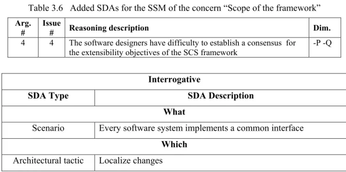
3.1.5 The activity “Create a SSM” – iteration 2 ... 75
3.1.6 Analysis of the case study ... 75
3.1.7 How the SAM framework addresses the conclusions of the case study .... 76
3.2 Case study: the SAM framework for analysing the TM design pattern ...77
3.2.1 Description of the TM design pattern ... 77
3.2.2 SSM of the TM design pattern ... 78
3.2.3 Arguments related to the TM design pattern ... 80
3.3 Experiment: human participants for applying the reference model ...87
3.3.1 Experiment planning ... 87
3.3.2 Experiment process and schedule ... 88
3.3.3 Experiment subjects, groups, and profiles ... 89
3.3.4 The design context and collected data ... 91
3.3.5 Statistics from the collected data ... 91
3.3.6 Analysis of the experiment ... 92
3.3.7 Limitations of the experiment ... 93
3.3.8 How the SAM framework addresses the conclusions of the experiment ... 93
3.4 Case study: the classification technique for analyzing catalogs of DK ...95
3.4.1 SSM of the Layered style ... 95
3.4.2 SSM of the modifiability tactics ... 97
3.4.3 An analysis of the results of the case study ... 100
3.5 Case study: the SAM framework for designing a web site ...102
3.5.1 Context of the case study ... 102
3.5.2 Decision points considered for the case study ... 103
3.5.3 SSMs created for developing the web site ... 104
3.5.4 Analysis of the case study ... 111
3.5.5 Limitations of the case study ... 112
3.6 Experiment for evaluating the SAM framework with a human participant ...113
3.6.1 Context of the experiment ... 113
3.6.2 Experiment planning ... 114
3.6.3 Experiment process and schedule ... 114
3.6.4 Experiment subject ... 115
3.6.5 Participant profile ... 116
3.6.6 Design context and data collection ... 116
3.6.7 Part 1 – SSM created by the participant for the TM design pattern ... 116
3.6.7.1 Analysis of Part 1 ... 118
3.6.7.2 Conclusions of Part 1 ... 120
3.6.8 Part 2 – SSMs created for developing the web site ... 122
3.6.8.1 Analysis of Part 2 ... 124
3.6.8.2 Conclusions of Part 2 ... 126
3.6.9 Limitations of the experiment ... 126
CHAPTER 4 A TECHNIQUE FOR CREATING A SOFTWARE STRUCTURES MAP ..127
4.1 The proposed classification technique ...127
4.2 The tasks of the classification technique ...129
4.3 Task 1 – Extract verbs and nouns ...129
4.4 Task 2 – Identify SDAs and relationships ...130
4.5 Task 3 – Classify the SDA ...131
4.5.1 The Zachman Framework for Enterprise Architecture ... 131
4.5.2 The proposed classification scheme (CS) ... 132
4.5.3 The proposed decision tree ... 135
4.6 Task 4 – Format the relationship ...140
4.6.1 The proposed relationship description format ... 141
4.7 Task 5 – Structure the SDAs ...142
4.8 Task 6 – Infer the SSM ...142
4.8.1 The proposed inference heuristics ... 143
4.8.2 The proposed Software Structures Map (SSM) ... 147
4.9 Summary of contributions...148
CHAPTER 5 A TECHNIQUE FOR DESCRIBING ARGUMENTS ...149
5.1 Introduction ...149
5.2 The tasks of the argumentation technique ...151
5.3 Task 1 – Select the SDAs and relationships ...152
5.4 Task 2 – Select the activities ...152
5.5 Task 3 – Elicit the issues ...152
5.5.1 The proposed issue description format ... 152
5.5.2 The proposed common issues ... 153
5.5.3 The proposed issue validation heuristics ... 154
5.6 Task 4 – Select the dimensions ...155
5.7 Task 5 – Describe the arguments ...156
5.7.1 The proposed argument description format ... 156
5.7.2 The proposed argument validation heuristics ... 157
5.8 Summary of contributions...158
CHAPTER 6 A TECHNIQUE FOR ANALYZING ARGUMENTS ...159
6.1 Introduction ...159
6.2 The tasks of the analysis technique ...160
6.3 Task 1 – Rank the activities and dimensions ...161
6.4 Task 2 – Select the SDAs and relationships ...161
6.5 Task 3 – Describe the structured arguments ...161
6.5.1 The proposed structured argument format ... 162
6.6 Task 4 – Rank the arguments and generate views ...163
6.6.1 The proposed multi-dimensional views ... 163
6.7 Summary of contributions...165
CONCLUSION AND FUTURE WORK ...167
Research contributions ...167
How the SAM framework addresses the research goal and objectives ...168
APPENDIX I DESIGN ACTIVITIES AND SOFTWARE DESIGN ARTIFACTS ...173
APPENDIX II EXAMPLE OF A SSM FOR AN OBJECT-ORIENTED FRAMEWORK 185 APPENDIX III THE SSMS OF THE MODIFIABILITY TACTICS ...195
APPENDIX IV INPUTS AND OUTPUTS OF THE EXPERIMENT (SYS869) ...207
APPENDIX V INPUTS AND OUTPUTS OF THE CASE STUDY (WEB) ...219
APPENDIX VI INPUTS AND OUTPUTS OF THE EXPERIMENT (WEB) ...225
LIST OF TABLES
Page
Table 1.1 Example of a representation scheme used to describe the architectural styles ...18
Table 1.2 Example of a representation scheme used to describe the design patterns ...20
Table 1.3 Measures, formula, and operands for maintainability [Iso9126] ...23
Table 1.4 The proposed activities of the design process ...39
Table 1.5 Architecture decision description template (adapted from Tyre05) ...41
Table 1.6 Current state of the research on design decisions ...42
Table 1.7 Issues for design knowledge management ...47
Table 1.8 Activities, techniques, and issues of the DK management process ...49
Table 2.1 Methods requirements coverage ...61
Table 2.2 Assessment of the rules for architectural documentation ...64
Table 2.3 Assessment of the SAM framework for the related works on design decisions ...65
Table 2.4 Limits of the SAM framework ...65
Table 3.1 The SSM of the architectural concern “Scope of the framework” – version 1 ...71
Table 3.2 Issues related to the architectural concern “Scope of the framework” ...72
Table 3.3 Arguments related to the SSM of the concern “Scope of the framework” ...73
Table 3.4 Rankings for the activities, dimensions, and arguments of the SCS framework ..74
Table 3.5 View of the SCS framework arguments ...74
Table 3.6 Added SDAs for the SSM of the concern “Scope of the framework” ...75
Table 3.7 The SSM of the Template Method design pattern ...78
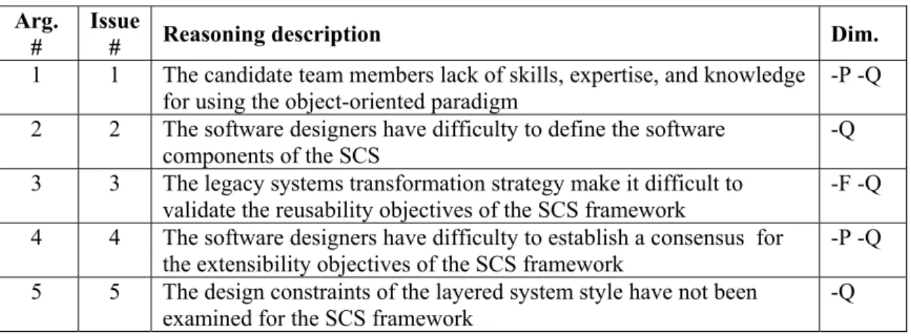
Table 3.8 Relationships between the SDAs of the Template Method design pattern ...80
Table 3.11 Design pattern description: sections and SDAs ...85
Table 3.12 Classification counts for the SDAs of the TM design pattern ...85
Table 3.13 Number of participants and missing responses, and ratio of missing responses ..91
Table 3.14 The SSM of the Layered style...95
Table 3.15 The SSM of the modifiability tactics ...97
Table 3.16 Style description: sections and SDAs ...100
Table 3.17 Classification counts for the SDAs of the Layered System style ...101
Table 3.18 Classification counts for the SDAs of the modifiability tactics ...101
Table 3.19 The decision points used for triggering the activities of the SAM process ...103
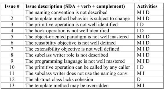
Table 3.20 Issues for the SAM framework ...111
Table 3.21 SDAs identified by the participant without using the SAM framework ...117
Table 3.22 SSM created by the participant for the TM design pattern ...117
Table 3.23 SDAs that were not identified by the participant ...118
Table 3.24 Summary of utilization of the SAM framework for Part 1 ...119
Table 4.1 Verbs and nouns that describe the “Exception Detection” tactic in [Scot09] ...130
Table 4.2 The proposed classification scheme of the SAM framework ...134
Table 4.3 The descriptions of some SDAs related to the Why interrogative ...137
Table 4.4 The descriptions of some SDAs related to the When interrogative ...138
Table 4.5 The descriptions of some SDAs related to the What interrogative ...139
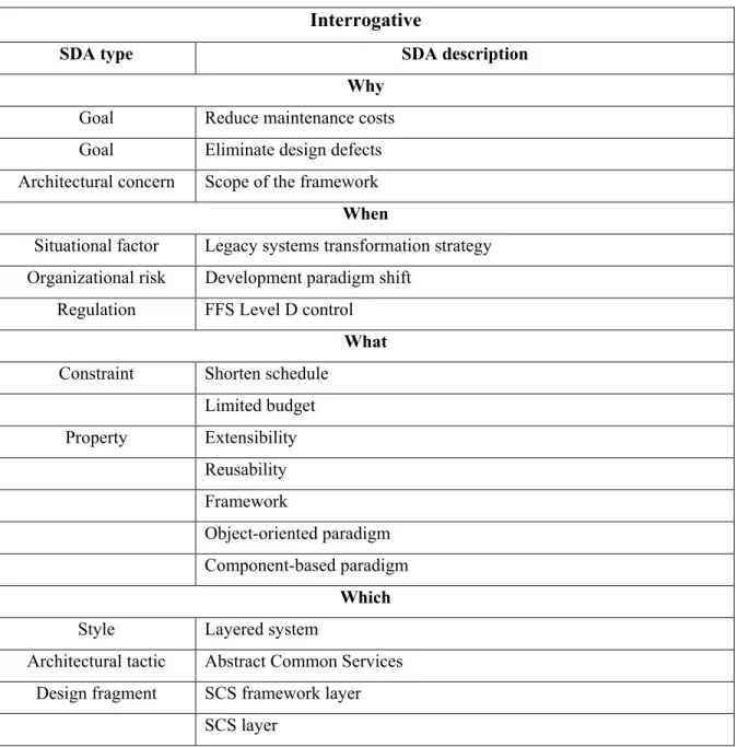
Table 4.6 The descriptions of some SDAs related to the Which interrogative ...139
Table 4.7 The descriptions of some SDAs related to the How interrogative ...140
Table 4.8 The descriptions of some SDAs related to the Where interrogative ...140
Table 4.9 The relationships of the SAM framework...141
Table 4.11 Inference heuristics for the SDAs related to the When interrogative ...144
Table 4.12 Inference heuristics for the SDAs related to the What interrogative ...145
Table 4.13 Inference heuristics for the SDAs related to the Which interrogative ...146
Table 4.14 Inference heuristics for the SDAs related to the How interrogative ...146
Table 4.15 Inference heuristics for the SDAs related to the Where interrogative ...147
Table 4.16 The table format used for representing a SSM ...148
Table 5.1 Examples of issue descriptions using a SDA, a verb, and a complement ...153
Table 5.2 The proposed list of verbs ...153
Table 5.3 Examples of common issue descriptions for the SAM framework ...154
Table 5.4 The proposed issue validation heuristics ...155
Table 5.5 The proposed dimensions of the SAM framework ...156
Table 5.6 Factors constituting the argument description of the SAM framework ...157
Table 5.7 The proposed argument validation heuristics ...158
Table 6.1 The structured argument format ...162
Table 6.2 Example of a generic multi-dimensional view ...163
Table 6.3 Contextualization of the dice game framework ...164
LIST OF FIGURES
Page
Figure 1.1 The client-server architectural style ...2
Figure 1.2 The increase available resources architectural tactic ...2
Figure 1.3 Activity diagram of the research methodology ...9
Figure 1.4 Proposed structure of software design artifacts in the SAM framework ...53
Figure 2.1 Overview of the Software Architecture Mapping (SAM) framework ...56
Figure 2.2 The proposed SAM process ...57
Figure 2.3 Overview of the Software Architecture Mapping process ...58
Figure 2.4 The proposed reference model of the SAM framework ...59
Figure 3.1 Overview of the process planned for the experiment ...88
Figure 4.1 The proposed classification technique of the SAM framework ...128
Figure 4.2 Perspectives of the CS: organizational, design, problem, and solution ...134
Figure 4.3 The decision tree for classifying a design knowledge item ...136
Figure 5.1 The argumentation technique of the SAM framework ...150
Figure 6.1 The analysis technique of the SAM framework ...160
LIST OF ABREVIATIONS
ABAS Attribute-Based Architectural Styles ADD Attribute-Driven Design
ADL Architecture Description Language CS Classification Scheme
DD Design Decision
DK Design Knowledge
EA Enterprise Architecture
GOF Gang-Of-Four
IEC International Electrotechnical Commission (www.iec.org) IEEE Institute of Electrical and Electronics designers (www.ieee.org) ISO International Organization for Standardization (www.iso.org) OCL Object Constraint Language
OWL Web Ontology Language
SAD Software Architecture Description SAM Software Architecture Mapping SDA Software Design Artifact SDD Software Design Description
SEI Software Engineering Institute (www.sei.cmu.edu) SIS Software-Intensive System
SSM Software Structures Map SWRL Semantic Web Rule Language
INTRODUCTION Software Engineering and Software Architecture
Software engineering is defined as the systematic, disciplined, quantifiable approach to the development, operation, and maintenance of software to improve its quality; i.e., its ability to support the stakeholders’ needs [IEEE610]. In particular, software designers improve the level of software quality by educating themselves and using bodies of knowledge, standards, best practices, and certification mechanisms [Kruc06].
The software designer’s community considers the design process, the software architecture it provides, and the reuse of design knowledge as fundamental levers for quality [Iso42010, Ovas10, Kim09, Scot09, Shaw06, Bert05, Bass03, Bach03, Clem03]. In the “Guide to the Software Engineering Body of Knowledge – SWEBOK”, software architecture design is a key sub-area of software engineering [Abra01, Garl00a].
Software architecture describes design elements from which software products are built, interactions among those elements, patterns that guide their composition, and constraints on these patterns [Medv00]. Several studies (e.g., [SEI11, Bass03, Shaw96, Garl95]) list benefits of an appropriate architecture and conclude that the quality of a software system depends largely on the quality of its architecture. During the development process, the systematic development of complex software architecture that supports the specified quality requirements remains a major challenge.
The Design Knowledge (DK) Base
Much knowledge and support for software design is provided by the software architecture literature including catalogs of styles, design patterns, and tactics, design decisions and quality models (e.g. [Iso42010, Iso25000, Zimm12, Ovas10, Zimm09, Kim09, Scot09,
Design decisions, styles, design patterns, and tactics are used to explicitly describe reusable design knowledge (DK). An architectural style and a design pattern organize the design elements in a way that has been recognized as a proven solution to a design problem. Each design decision, style, design pattern, and tactic may promote or disadvantage one or more quality requirements. Software designers describe and use the DK in various ways for building software that support the quality requirements. The inadequate usage of DK may cause significant impact on software quality when the most prioritized quality requirements are disadvantaged. The software designers need to add many details to produce an implementable design, which may reduce the claimed benefits of the styles, design patterns, or tactics.
For example, Figure 1.1 presents the Client-Server architectural style and Figure 1.2 presents the increase available resources architectural tactic. To maintain the system level of performance when the number of clients increases, the Client-Server style facilitates the addition of a second server. The addition of a server and its interactions with the clients may reduce the level of security of the system, which has more possible points of attack for intruders. In such a context, the architects need to take decisions among a large space of solutions [Scot09].
Figure 1.1 The client-server architectural style
Figure 1.2 The increase available resources architectural tactic
The Software Designer Role
The software designers execute many activities described in [Bass03] for designing a software product with proven characteristics of quality. To take into account multiple objectives during the design process, the software designers select and prioritize the quality requirements that are architecturally relevant. The most prioritized quality requirements are called the architectural drivers. The software designers use the architectural drivers to make design decisions for designing parts of the architecture. Each decision may affect one (sensitivity point) or more (tradeoff point) quality requirements. The software designers have to evaluate alternatives and make tradeoffs among conflicting decisions in order to reduce risks and determine sets of design decisions that best support the project objectives.
Research Problem
There are multiple sources (users, marketing, etc.) and categories (constraints, business drivers, technical limits, etc.) of project objectives relating to the software design process. The evaluation of many design decisions is made before any software is built. A lack of detail about either the problem or solution space may lead software designers to inappropriate or suboptimal design decisions [Kozi11]. The software designers employ the DK base to understand, tailor, and describe alternate designs that have proven to be useful for previous projects with comparable contexts and project objectives.
Styles, design patterns, and tactics are mostly described in textual format. They may be complex and their interactions are not always evident. The software designers need to add significant amounts of details to produce an implementable design, which may reduce the claimed benefits of the styles, patterns, and tactics. To take full advantage of accumulated knowledge, the software designers need frameworks and tools to manage the DK and relate it to the decisions taken and software design artifacts (SDAs) used for designing the software.
The software designers need to discern:
1. the SDAs, issues, and arguments that best describe the design context;
2. the design decisions including styles, tactics, and design patterns that produce the best balance across orthogonal, complementary, and antagonistic objectives ; and
3. the objectives that are affected by the styles, design patterns, and tactics used.
The objectives include the quality requirements that should be precisely defined since the architecture is built to support them. Systems often have different sets of requirements for different modes of execution. Many of the particular quality requirements are in conflict (e.g., adding efficiency is often realized at the price of portability and maintainability) and the qualitative nature of these requirements makes the appropriate levels of satisfaction difficult to clarify. Evaluating the impacts of a set of design decisions on a set of objectives is a complex activity. In particular, the design context may be complex considering the nature of the objectives, the number of SDAs, including styles, design patterns, and tactics available, and their relationships with the quality requirements.
Many organizations maintain design decisions, SDAs, and tailored information items in a DK base to help document control, development, and maintenance activities. Most of the models, methods, and tools provide limited analysis capability and views in the DK base [Ovas10, Bach07, Bass05, Tyre05, Bass03, Clem03]. Reusing the DK contributes to the design capability of the organizations and accrues returns of investments in designing the software and building the systems [Bass03]. By managing the artifacts produced for designing software-intensive systems, the software designers may reuse the resulting DK during the development and decision processes of current and future projects.
The software designers encounter at least three problems when analyzing the design context and the effects of the design decisions on a set of objectives:
1. The representation schemes and design document templates usually used to share the DK (i.e., design decisions, styles, patterns, and tactics) force the software designers to extract and infer the finer-grained decisions, context knowledge, and explications about how the SDAs impact the objectives from the textual descriptions.
2. The issues and the impacts are merely discussed in terms of quality characteristics making it hard to evaluate which decision is better than others in a particular context. 3. The techniques, models, and tools that support the DK management usually aim at
sharing the design decisions using templates and do not support sharing finer-grained SDAs and other activities such as acquiring, reusing, evaluating, and maintaining DK.
Research Question, Hypothesis, and Approach
This doctoral project is characterized in terms of the research question it investigates, the research approach it adopts, and the criteria by which it evaluate the results. From our point of view, the software design artifacts (SDAs) constitute the explicit DK. For this doctoral project, the research question was: “what is a good DK management approach (i.e., DK model and techniques) for supporting the software designers when inferring and describing SDAs and DK related to particular decisions points of the design process?”
The design decisions are useful for aggregating cohesive sets of SDAs at particular decisions points during the design process. The research’s main hypothesis was that a valuable DK management approach should provide techniques for:
- managing the finer-grained SDAs that relate to each decision point;
- describing the design decisions, issues, and impacts using the finer-grained SDAs; and - supporting the inference of the SDAs and issues related to a particular decision point. Finally, a valuable approach should be assessed using the requirements for DK management defined in the literature.
The research hypothesis has been verified using a conceptual, theoretical, and qualitative empirical research approach. The conceptual part was required to identify and clarify the meaning, relationships, descriptions, and use of the finer-grained SDAs in to order to make specific proposals about how to manage them. The theoretical part was required to develop a reference model and techniques for managing the DK and the related SDAs, issues, and impacts. The qualitative empirical part was required to demonstrate the reliability and usability of the proposed reference model and techniques for managing the DK.
Research Goal, Research Sub-Goals and Research Objectives
The research goal was to develop supports for guiding the software designers when inferring the context of the design decisions during the design process. To tackle this research goal the following research strategy has been chosen:
1. identify and understand the descriptions of SDAs from catalogs of styles, design patterns, and tactics, and software architecture and software design documents. 2. structure the SDAs in a reference model for DK management; and
3. develop techniques for acquiring DK and supporting the software designers when using the reference model and DK base of SDAs during the design process.
This research project has permitted to develop an approach using the existing works, of [Iso42010, Iso12207, Zimm12, Ovas10, Zimm09, Kim09, Scot09, Gran08, Bach07, Kruc06, Tang06, Bass05, Tyre05, Bass03, Clem02, Abra01, Gamm95].
The research goal includes the following sub-goals (A-C) and research objectives (1-7).
Sub-goal A. Develop a description format for describing the SDAs and relationships that are
used by the software designers during the design process.
Research objective 1: Establish descriptive criteria for describing the finer-grained SDAs
Research objective 2: Establish exclusive criteria for classifying these finer-grained SDAs.
Research procedure: This research objective requires studying and representing with descriptive and exclusive criteria the finer-grained SDAs. The resulting criteria will be used to develop a description format for describing the SDAs, including styles, design patterns, and tactics.
Sub-goal B. Define a reference model for representing the SDAs and their relationships. Research objective 3: Develop a structure for creating semantic networks of SDAs that may
be used for describing styles, design patterns, and tactics.
Research procedure: A semantic network is used as a form of knowledge representation; it represents semantic relations between concepts. Relating finer-grained SDAs that relate to the styles, design patterns, and tactics in a semantic network will allow to represent the SDAs as instantiations of semantic networks. The styles, design patterns, and tactics will instantiate common nodes and relations for constituting the semantic networks using aggregations of SDAs. The reference model should be suited for representing the node types (e.g., Tactic) and relations (e.g., Mandatory or Exclusive-or) of the semantic networks.
The related works on tactics, styles, and design patterns should be the starting points for populating the design knowledge base using the descriptions given in [Bass03, Clem03, Gran02, Gamm95]. Such aggregations of artifacts should make discernible every part of the styles, design patterns, and tactics descriptions, instead of using the textual format that obscures significant information.
Research objective 4: Define an argument format for describing the impacts of particular
Research procedure: Describing the arguments that relate to the utilization of the SDAs will allow to populate a design knowledge base of common issues and arguments. The styles, design patterns, and tactics will relate to common issues and arguments.
Sub-goal C. Systematize the utilization of the reference model and descriptions formats. Research objective 5: Establish a technique and work instructions that help the software
designers populate a design knowledge base using the reference model, and the descriptions of styles, design patterns, and tactics.
Research objective 6: Establish a technique and work instructions that help the software
designers populate a design knowledge base of arguments that relate to particular utilizations of SDAs.
Research objective 7: Establish a technique and work instructions that help the software
designers analyze the impacts of particular utilizations of the SDAs.
Originality and Expected Benefits
Many studies have proposed different models, techniques, and tools to describe and reuse the design knowledge (DK) [Ovas10, Kim09, Scot09, Harr08, Bach05, Bass03, Clem03]. However, previous studies have underlined the importance of having a reference model (RM) and the related techniques that can be used for managing the DK (see Section 2.4.3) using the finer-grained SDAs related to the design decisions, design patterns, tactics, and styles. This research is a step toward understanding, describing, and reusing the design decisions, tactics, design patterns, and styles, and their relationships to other SDAs of the DK base.
Five research deliverables were produced for this research project:
• a Reference Model (RM) for describing the SDAs, issues, and arguments; • a Design Knowledge (DK) base of tactics, patterns, and styles knowledge; • a technique for populating a DK base of SDAs using the RM;
• a technique for populating a DK base of arguments using the RM; • a technique for reusing the DK base while designing.
Research Methodology
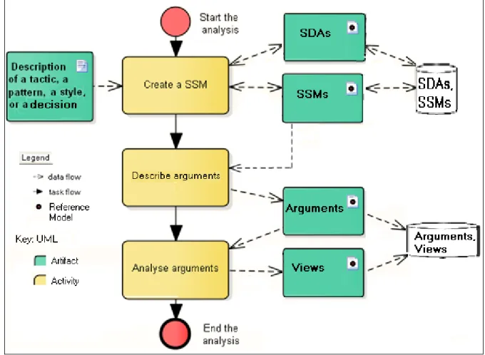
Figure 1.3 presents the phases, activities, and outcomes of the research methodology that have been executed. The phases are subdivided into lists of tasks and detailed in the next subsections.
Phase 1 – Collect Data
Phase 1 aimed at collecting data about the software design artifacts (SDAs) and their relationships. The following research tasks have been executed:
• Study the literature review for the state-of-the-art on design approaches, software design artifacts (SDAs), and design knowledge (DK) management.
o Analyze models, techniques, and tools relating to SDAs and DK management. o Analyze techniques and tools that use DK bases to support software designers. • Summarize the state-of-the-art for design approaches, SDAs, and DK management. • Identify the finer-grained SDAs that provide DK, including the SDAs that relate to
the styles, design patterns, and tactics descriptions.
o Identify the issues relating to DK management and SDAs.
• Establish the software architecture mapping (SAM) framework for classifying SDAs. • Apply the SAM framework in a case study.
Outcomes: literature review (see Chapter 1), classification scheme and SDA description
format (see Chapter 4), case study (see Chapter 3 and Appendix I).
Phase 2 – Develop the Reference Model
Phase 2 aimed at developing the reference model and convey the design knowledge extracted from the literature review. The following research tasks have been executed:
• Describe the node types and relations of the semantic network of SDAs.
• Describe the argument format and relations of the semantic network of arguments. • Develop the concepts of the reference model that constitute the semantic networks. • Case study: Apply the reference model to the description of the tactics, design
patterns, and styles given in [Scot09, Bass03, Clem03, Gamm95].
Phase 3 – Develop techniques
Phase 3 aimed at developing the techniques for using the reference model. The following research tasks have been executed:
• Develop heuristics for identifying the SDAs.
• Develop a classification scheme and a decision tree for classifying the SDAs.
• Develop steps and work instructions that support using the reference model for populating a DK base of semantic networks of SDAs.
• Develop steps and work instructions that support using the reference model for populating a DK base of semantic networks of arguments.
• Develop steps and work instructions for using the DK base of related SDAs and arguments for analysis the impacts of utilization of the SDAs in project contexts.
Outcomes: classification technique (Chapter 4), argumentation technique (Chapter 5),
analysis technique (Chapter 6), case study (Chapter 6).
Validation of Research Results
This section summarises the validation objectives and validation scope, and activities that have been conducted for validating the proposed Software Architecture Mapping (SAM) framework. As stated in [Zimm09], “research contributions in software engineering must be validated. A validation of the monetary value and business benefits such as opportunities to increase revenue or reduce cost would be required when creating a business case for the development of a commercial version of the proposed solution”. Such an analysis is difficult to perform in practice [Zimm09] and was not a primary goal of the thesis validation. “The important validation objectives were to evaluate technical feasibility, to confirm the practical value for the target audience, and to evaluate the usability. Practical value and usability have been considered but remain to be evaluated in more details, i.e., whether software designer are willing and able to apply the SAM framework and whether such application is beneficial”
Validation Activities
The case studies and experiments described in CHAPTER 3 and a self-assessment of requirements served as the primary validation activity types. The evaluation activities focused on confirming the key hypothesis that SDAs, SSMs, arguments, and views recur and can be modeled according to the reference model.
The case studies have been developed to evaluate the technical feasibility of the SAM framework concepts by creating:
- the SSMs of a framework in the context of software cockpits;
- the SSMs of a web site in the context of a web engineering project; and
- the SMMs of design patterns, styles, and tactics used in software engineering courses. The experiments have been conducted with human participants for evaluating the reliability, efficiency, accuracy, and usability of the SAM framework.
1. For the first experiment, selected research results were proposed to participants for eliciting issues and describing arguments related to the design of a framework in the context of a detailed design course at ÉTS.
2. For the second experiment, selected requirements were proposed to a participant for creating the SSMs, eliciting the issues, and describing the arguments related to the design of a web site. In addition, the participant was required to create the SSM of the Template Method design pattern.
Another validation activity was to conduct self-experiments. For instance, previous versions of the SAM framework have been used for teaching the software architecture and detailed design courses at ÉTS. These activities helped to ensure that the developed reference model is applicable for software designers independent of their expertise and experience.
Finally, a self-assessment of requirements has been conducted using the requirements catalog described in section 2.6 as a source of validation criteria for the case studies. In addition, a
The preliminary validation results were used to improve subsequent versions of the SAM framework and reference model. The validation produced sufficient evidence that the core concepts such as the reference model work in practice. The justification for conducting case studies is that the selected cases yielded a reasonable coverage of the concepts proposed in the SAM framework without causing unmanageable validation efforts for the involved researchers and the case study participants.
Thesis Organization
The thesis is organized as follows.
CHAPTER 1 presents the literature review. This chapter introduces the basic concepts (i.e., software architecture, styles, tactics, design patterns, and characteristics of quality) related to the software architecture design and detailed design. This literature review provides the synthesis on the works, challenges, and issues related to:
1) the representation of styles, tactics, and design pattern; 2) the activities and artifacts of the design process; and 3) design knowledge (DK) management.
It also provides a summary of the requirements for design methods and DK management. Finally, it describes the proposed structure of software design artifact (SDA) that is the basic concept for developing our approach. Appendix I describes the SDAs of the design process.
CHAPTER 2 presents the proposed Software Architecture Mapping (SAM) framework, SAM process, and the reference model for managing the SDAs. This chapter presents the arguments justifying the reference model and describes its limits. This chapter also compares the SAM framework with approaches in the literature review and presents its limits.
CHAPTER 3 presents seven examples of utilizations of the SAM framework, including five cases studies and two controlled experiments. These examples are the outputs of the validation process for evaluating the SAM framework. This chapter describes the software structures maps (SSMs) that were created, the SDAs that were classified, the arguments that were described for various academic and industrial contexts.
CHAPTER 4 presents the classification technique for creating a Software Structures Map (SSM) that classifies and relates the SDAs.
CHAPTER 5 presents the argumentation technique for relating the software design artifacts (SDAs) to the activities and dimensions they impact. This technique supports the elicitation of the issues and the description of the arguments that relate to the utilization of the SDAs.
CHAPTER 6 presents a technique for supporting the analysis of the arguments using multi-dimensional views. This technique supports the systematic inference of
• the order of treatment of arguments related to a context of application of SDAs; and • the order of utilization of the related design knowledge.
CHAPTER 7 presents the conclusions, contributions, and future work of this research project.
CHAPTER 1 LITERATURE REVIEW 1.1 Basic Concepts
1.1.1 Software Development Approach
The international standard ISO 29110 on Lifecycle Profiles for Very Small Entities (VSEs) [Iso29110] propose a set of activities that constitute any software development approach for very small entities (i.e., enterprise, organizations, departments, or projects – up to 25 people). Such entities often implement software used in larger systems that require suppliers of high quality software. This standard decomposes the software development into two processes: project management (PM) and software implementation (SI). An output of the PM process is the project plan. The purpose of the SI process is the systematic execution of the analysis, design, construction, integration and tests activities for implementing software products according to the project plan and the specified requirements. The standard integrates practices based on the selection of standards elements from ISO 12207 on Software life cycle processes [Iso12207], and ISO 15289 on Content of life-cycle information items (documentation) [Iso15289] for the PM and SI processes. The focus of this thesis is on the SI process.
The execution of the SI process is driven by the project plan, which guides the execution of the software requirements analysis, software architectural and detailed design, software construction, software integration and test, and product delivery activities. The customer usually provides a statement of work as an input to the development approach. The PM process establishes a project plan based on the statement of work. The software designers use the project plan to perform the SI process in order to produce a software configuration that satisfies the customer and other stakeholders. More precisely, the focus of this thesis is on the software architecture design and detailed design.
1.1.2 Software Architecture Design and Detailed Design
Software requirements are defined, analyzed for correctness and testability, approved by the stakeholders, baselined, and communicated to software designers who will design the software. Software architecture design and detailed design are usually performed separately in order to describe the software components and connectors and their related software units. Subsequently, the software construction activity produces and tests the software units in order to verify their consistency with requirements and the design. The software is produced, including performing integration of software units, components and connectors. The verification and validation of the work products are performed in order to achieve consistency among the work products in each activity. Finally, the software configuration is integrated and delivered to the acquirer in accordance with the agreed requirements.
First in the design, the software architecture design (SAD) activity aims at developing the software architecture. The SAD produces the software components and connectors, their internal and external interfaces, and their topologies and semantics [Iso12207, Bass03]. The SAD aims at establishing consistency and traceability between software design and software requirements.
Second, the software detailed design (SDD) activity aims at developing a detailed design of each component and connector. The SDD describes the software units that compose each component and connector, including the external interfaces, structures, and sequences of interactions of the units [Iso12207]. The SDD aims at establishing consistency and traceability between detailed design, software requirements, and architectural design. For some authors [Bass03, Clem03], the software architecture is the most important deliverable; and the establishment of the consistency and traceability between detailed design, software requirements, and architectural design is a challenge.
1.1.3 Software Architecture
The literature defines the software architecture from many perspectives [SEI11, Bass03, Clem03, Medv00]:
1. a centerpiece artifact;
2. the set of principal design decisions about the software system;
3. the software design artifacts that pervade all major facets of software systems; the description of elements from which systems are built, interactions among those elements, patterns that guide their composition, and constraints on these patterns; 4. the software structures (e.g., modules; components and connectors; or allocation) of
the system;
5. the set of elements such as modules (e.g., class), components and connectors (e.g., process), and their visible properties, behavior, and relationships (e.g., synchronization) in different structures and contexts (e.g., execution);
6. the set of principal design decisions about the software system that pervade all major facets of a software system, including structural, deployment, non-functional, evolution, and runtime concerns [Medv00]; and
7. the structures of the software system composed of several types of elements (e.g., class and process) and relationships (e.g., subdivision and synchronization).
There is no universally accepted definition of software architecture [Clem03], although it is a centerpiece artifact for software designers and its roots run deep in software engineering [SEI11, Abra01, Garl00a]. The software architecture concerns the externally visible portion of the elements; it represents an abstraction of the software system. It defines elements such as software components and connectors along with their relationships (topology), behavior, and visible properties. Externally visible properties refer to those assumptions other elements can make of a component or a connector [Clem03]. The software architecture describes how a component uses, is used, is connected to, and interacts with other elements in different contexts (e.g., compilation and execution).
As presented in [Clem03], the software architecture is what makes the sets of elements work together as a successful whole. [Perr92] proposes the following model: Software Architecture = {Elements, Form, Rationale}. This model refers to processing elements, data elements, and connecting elements. In [Bass03], the authors refine the model where Software Architecture = {Components and Connectors, Topology and Semantic, Rationale}.
1.1.4 Architectural Style and Tactic
Architectural styles are important software design artifacts that allow a software designer to reuse the collected wisdom of the architecture design community to solve recurring problems [Klei99]. Table 1.1 provides an example of a representation scheme used to describe the architectural styles. The representation scheme is used to describe the properties, components and connectors, relations, constraints, and strengths of the Layered System architectural style. An architectural style organizes the components and connectors of the software architecture [Bass03]. It describes known properties and patterns of data and control interaction among the components [Shaw96, Busc96]) to enable reuse and evolution of the design [Klei99]. It is a package of decisions that allows reasoning about the system design in terms of desired properties [Bass03]. It defines how to carry out the design and imposes constraints, semantics, vocabularies, and types for the components and connectors, along with qualitative reasoning about the strengths and weaknesses of the design [Klei99, Garl94]. An architectural style helps to interpret and analyze the software architecture.
Table 1.1 Example of a representation scheme used to describe the architectural styles
Properties
• A layer is an intermediary between software, hardware, or layers.
• Each layer has a public interface that provides a cohesive set of services. • The public interface is more than just the API (assumptions, etc.). • A change in one layer does not affect the lower layers.
Components / Connectors
• One or more layers are defined.
• The name, content, and cohesion scheme of each layer is specified.
Relations
• The inter/intra-relationships of each layer are specified. • The exceptions of each layer are specified.
Constraints
• The order of interaction is important (closest layer, layer bridging, etc.). • The use of the upper layers is prohibited (except: exceptions, data flow, etc.). • A layer cannot be above and below another layer at the same time.
• Each software component is allocated to a single layer.
Strengths
• Permit system evolution. • Facilitate work assignment. • Favor reuse.
• Manage complexity.
A style packages many tactics: architectural tactics are the building blocks of the software architecture and styles [Bass03]. They are among the first design decisions made during the development process. As presented in [Scot09], “architectural design is a complex search through a large space of possibilities, the use of tactics guides and constrains this search and makes it more tractable. A tactic suggests an analytic model for design and analysis, which may range from guidelines and heuristics to precise mathematical models”.
A tactic may help to increase the level of quality of a system. Each tactic specifies how a quality attribute can be controlled through design decisions to achieve a response [Bass05]. For example, layering a system may increase maintainability by isolating a system from changes in the underlying platform. The layer style achieves this isolation by using many tactics described in [Scot09, Bach07, Bass03]: Semantic Coherence, Abstract Common Services, Use Encapsulation, Use an Intermediary, and Restrict Communication Paths. A tactic is a decision for tailoring software designs, styles, and design patterns.
1.1.5 Design Pattern
As mentioned in [Clem03], styles and design patterns “are alike in that both are catalogued partial design solutions, captured in practice, and must be instantiated and completed before application to an actual system”. However, “a style tends to refer to a coarser grain of design solution than a pattern”. Design patterns are usually finer-grained engineering artifacts that pact together a set of design decisions such as tactics and describe how they affect software product quality. Both design patterns and styles package a set of tactics.
A design pattern describes a general solution to a recurring problem that occurs under specific circumstances [Gran02, Gamm95]: it organizes the software modules in a way that has been recognized as a proven solution to a design problem. It describes the design concerns to be solved and the software design it proposes to address these concerns. The general solution has been recognized to be useful for designing previous software products with comparable characteristics of quality. However, a design pattern is only advice, and the software designers have to figure out how to apply it to his circumstances. Software designers may use the same design pattern many times, but it is never exactly the same project-specific solution. Table 1.2 provides an example of a representation scheme used to describe the design patterns. In general, a design pattern description has four essential elements [Gamm95]: the pattern name, the problem it addresses, the solution it provides, and the consequences it implies. The representation scheme is used to describe the Template Method design pattern.
Table 1.2 Example of a representation scheme used to describe the design patterns
Pattern Name
• Template Method
Problem
• Implement the invariant parts of an algorithm only once
• Factor and localize common behavior to avoid code duplication • Control extension
Solution
Key: UML
Consequences
• Facilitate factoring out common behavior. • Permit inverted control structure.
• Reduce duplication of code. • Favor reuse.
A design pattern may be used to evaluate, before any software is built, how well the software design may support software product quality. To properly choose and apply the patterns and their related tactics, the software designers need to evaluate what characteristics of quality are affected by each of the design patterns and tactics used, and discern what set of patterns and tactics produces the best balance across the quality requirements. However, a pattern is complex and its interactions with other patterns and tactics are not always evident. In particular, the boundaries between the design patterns are fuzzy. As stated in [Fowl08], “designers can never just apply the solution blindly, which is why pattern tools have been such miserable failures”. Design decisions have to be made in order to use a design pattern.
1.1.6 Characteristics of quality
There are many definitions of software quality, each reflecting a particular quality philosophy and approach. A quality model, as proposed in [Iso9126, Gali04, Bass03], may be used to make the meaning of the quality requirements and the level of quality more precise and easy to evaluate for a system. The characteristics of quality of a software system such as maintainability or performance are usually defined in a quality model by specifying the set of quality attributes required for the stakeholders’ software acceptance [Bass03].
Software designers are required to analyze how their most relevant design decisions affect the characteristics of quality. The literature provides many definitions of software quality [Iso24765, Iso25000, Gali03]. In this thesis, software quality refers to the level to which a system, component, or process meets specified requirements as well as the needs and expectations of clients and users [Iso24765]. This vague definition is not useful in practice. Software designers may use quality models [Iso9126, Gali03] to make the meaning of quality requirements and the level of quality more precise and easy to evaluate.
The series of standards ISO 25000, also known as SQuaRE (System and Software Quality Requirements and Evaluation) [Iso25000], is a framework for the evaluation of software product quality. The international standard ISO 25010 on System and software quality models [Iso25010], and related works [Iso9126, Gali03, Bass03], recommend to hierarchically decompose software product quality into multiple characteristics.
The ISO 25010 standard provides a quality model that decomposes the software product quality into eight characteristics of quality: functionality, reliability, operability, performance efficiency, security, compatibility, maintainability, and transferability. Characteristics are further subdivided into subcharacteristics. Each subcharacteristic is further subdivided into a set of measures. For example, Table 1.3 presents the definitions of two subcharacteristics and three measures related to maintainability.
The standard proposes to use characteristics, subcharacteristics, and measures as a checklist of issues related to quality. Software designers use such measures, and other artifacts such as specific scenarios [Bass03], to specify the software quality requirements, evaluate the design decisions, and assess whether the resulting software meets the requirements or design objectives.
Table 1.3 presents three measures related to maintainability. Each measure (e.g., Activity recording) is defined by a formula (e.g., a / b) that contains the operands (e.g., a and b). The software designers assign values to the operands in order to reflect the design decisions that shape the software product. The software designers need to make design decisions that optimize a set of measures. Therefore, the design problem may be formulated by a set of threshold values assigned to the measures (e.g., Xi = 0.7). The threshold values are the targets software designers need to control when evaluating a software design. The evaluation results and the threshold values are compared to determine the software quality.
Table 1.3 Measures, formula, and operands for maintainability [Iso9126]
Sub- Characteristic
Maintainability Subcharacteristic Definition
Definition Measure, Formula, and Operands
Analysability
Capability of the software product to be diagnosed for deficiencies or causes of failures in the software, or for the parts to be modified to be identified
Activity recording X = A / B
A = Number of implemented data login items B = Number of data items to be logged Readiness of diagnostic function (DF) X = A / B
A = Number of implemented DFs B = Number of DFs required
Changeability
Capability of the software product to enable a specified modification to be implemented
Change recordability X = A / B
A = Number of implemented data login items B = Number of data items to be logged
1.2 Effects of Styles, Design Patterns, and Tactics on the Software Quality
As presented in [Scot09, Bass03, Clem03], both design patterns and styles package a set of tactics. These authors define a pattern or a style as a description of a solution to a multi-variable problem, and a tactic as a description of a solution to a single-multi-variable problem. A tactic is primarily used to support a single characteristic of quality in [Scot09, Bass03] but it may also be used to support multiple characteristics as well.
For example, the Layer pattern achieves portability by encapsulating platform-specific details behind stable interfaces. In this case, the tactic “Use Encapsulation” is necessary for both portability and maintainability. Each tactic may relate to a set of measures [Kozi11] for which the software designer measures the impact of the tactic on the software product’s quality. Each measure details a software quality objective. Each characteristic of quality may relate to multiple objectives.
The problem of attaining software product quality involves optimizing a set of orthogonal, complementary, and antagonistic targets. The software designers may express the design problem as a multi-objective optimization problem (MOOP) or a multiple objective non-linear programming problem [Kozi11, Ralp85, Stad84, Stad79].
This kind of problems has at least four definitions that software designers need to specify: 1. the set of objective functions that defines the problem-space;
2. the set of threshold values that defines constraints on the solution-space; 3. the set of solutions that defines the solution-space;
The set of objective functions may be specified using a vector M = [f1 … fm] of m measures formulas with M Ԑ Q, where Q is a quality model that defines objectives functions to maximize or minimize.
Software designers use threshold values to control that evaluation results are acceptable for all measures. The threshold values may be specified using a vector T = [t1 … tm] of m threshold values assigned to the measures formulas. The vector T specifies the acceptable evaluation results that candidate design solutions need to achieve. The threshold values are the degrees of freedom that constrain the solution-space S Ԑ C, where C is the search space.
In the set of solutions, each design solution provides a set s = (d1 … dn) of n design decisions (e.g., using a style, a design pattern, or a tactic) that defines the solution-space s Ԑ S. A design solution sc = (d1 … dn)c is a candidate solution if each of its related evaluation result ri for any measure formula fi (with only one formula for each measure) is at least equals to the related threshold value.
For a candidate solution sc, F(sc) represents the aggregate objective function that combines the evaluation results of a vector M(sc) = [fi(sc) | (1<=i<=m)] of m objectives functions. If the optimality is a maximum, max(F(sc)) represents a design problem that is a multi-objective optimization problem. The problem is the search of a candidate design solution sc of n design decisions that maximizes the aggregate objective function F in a solution-space S.
A weighted-sum approach may be used to let the software designers influence how a design decision d impacts a vector M = [f1 … fm] of m objective functions. Each objective function is multiplied by a weighted value £i, where Rm is a set of valid weighted values. The weights are usually based on the issues and the measures that need to be evaluated by the software engineers. The objective functions and the set of weights need to be normalized in order to sum values of consistent magnitudes.
1.3 Approaches for Representing Tactics, Design Patterns and Styles
To evaluate the effects of the design decisions (e.g., using styles or tactics) on the characteristics of quality, software designers need to represent and use these concepts in a manner that supports systematic evaluations. Catalogs of design artifacts such as tactics and styles allow a software designer to reuse the collected wisdom of the software engineers’ community to solve recurring problems [Bach07]. Representing appropriate DK in a format useful for supporting the software implementation process involves numerous vocabularies and constraints [Kim10a]. Software designs are based on styles, design patterns, and tactics that provide a domain-specific design vocabulary and constraints on the design solution.
This section presents a list of representation schemes used to describe styles, design patterns, and tactics. This analysis of the literature gives an idea of the general trends in the research community [Kim10a, Scot09, Bass03, Clem03, Ande01, Klei99, Shaw97, Bush96]. Software designers have worked on formalizing architecture documentation practice into the IEEE standard 1471-2000 [Ieee1471], a recommended practice for architectural description of software-intensive systems. This standard establishes a framework of concepts and a vocabulary for discussing architectural issues of software systems. It specifies the required content of architectural descriptions, which may be useful for understanding the required content of styles and design patterns descriptions. Clements et al. [Clem03] detail what should be contained in an architectural description.
1.3.1 Representation Schemes for Tactics
The tactics are finer-grained design decisions that constitute architectural styles and design patterns. This section presents three representation schemes for tactics: a catalog of architectural tactics [Scot09, Bass03], a UML-based graphical modeling notation for tactics [Kim10a, Kim09, Gies07, Booc99], and a formal representation of tactics [Wyet09]. An overview of advantages and disadvantages of these representation schemes is provided next.
1.3.1.1 Catalog of Architectural Tactics
A catalog of architectural tactics has been proposed in [Bass03]. In this catalog, each tactic (e.g., Increase available resources) is related to a quality attribute (e.g., Performance) and a specific interest (e.g., Resource management) that describes the issue to be solved. A tactic is documented in a textual format and describes the situation when it can be applied. It may be accompanied by box-and-line drawings that present the organization of the tactic’s components and connectors. Subsequent works have refined parts of the catalog and categorization introduced in [Bass03].
In [Scot09], the authors review the availability tactics. They refine some tactics into lower-level tactics (e.g., System Monitor is refined into Heartbeat and Watchdog). In addition to refining the categorization, the authors do the same as in [Bass03] and provide some examples of specific implementation techniques and the expected results for each tactic. To illustrate how a tactic is described in [Bass03] and [Scot09], the following description is taken from [Scot09]:
“Exception Detection refers to the detection of a system condition that alters the normal flow of execution. For distributed real-time embedded systems, the Exception Detection tactic can be further refined to include System Exceptions, Parameter Fence, and Parameter Typing tactics. System Exceptions will vary according to the processor hardware architecture employed and include faults such as divide by zero, bus and address faults, illegal program instructions, and so forth. The Parameter Fence tactic incorporates an a priori data pattern (such as 0xDEADBEEF) placed after any variable-length parameters of an object.”
![Table 1.5 presents the template proposed in [Tyre05] for capturing the information of a DDs](https://thumb-eu.123doks.com/thumbv2/123doknet/7402776.217533/65.918.153.849.505.958/table-presents-template-proposed-tyre-capturing-information-dds.webp)


![Table 3.8 summarizes the relationships extracted from [Gamm95] for the proposed SDAs.](https://thumb-eu.123doks.com/thumbv2/123doknet/7402776.217533/104.918.110.727.262.778/table-summarizes-relationships-extracted-gamm-proposed-sdas.webp)