STATIC PRESSURE RECOVERY ANALYSIS IN THE VANE ISLAND
DIFFUSER OF A CENTRIFUGAL PUMP
Qiaorui Si
1, Patrick Dupont
2, Annie-Claude Bayeul-Lainé
3, Antoine Dazin
3, Olivier Roussette
3,
Shouqi Yuan
1, Gérard Bois
3*1National Research Center of Pumps, Jiangsu University, China 2 LML, UMR CNRS 8107 Ecole Centrale de Lille, France 3 LML, UMR CNRS 8107, Arts et Métiers PARISTECH, France
*Corresponding author: Tel.:+03-20-62-22-23; fax: +03-20-62-20-40 E-mail address: Gerard.BOIS@ensam.eu
5th International Symposium on Fluid Machinery and Fluids Engineering (ISFMFE 2012) 24-27 October 2012, Jeju, Korea
Abstract
The overall performance of a vane-island type diffuser of a centrifugal pump model was obtained by means of directional probe traverses. These measurements were performed in an air model of a real hydraulic pump for five volume flow rates. Directional probe traverses are performed with a classical three-hole probe to cover most of the complete inlet section of the diffuser from hub to shroud and from pressure to suction side. Some assistance from already
existing URANS
calculation, including leakage effects, is used to evaluate the numerical approach capability and to correctly define the initial conditions that come from the impeller outlet section to evaluate pressure recovery and the measured total pressure loss levels inside this particular vane diffuser geometry. Detailed analysis of the flow structure at the inlet section of the vane island diffuser is presented to focus on local pressure loss during the vaneless gap after the impeller and
incidence angle
distributions along hub to shroud direction. Previous 2C-2D particle image velocimetry measurement results are also given to
compare probe
measurements between the inlet throats and outlet of vane island diffuser at mid-span.
1. Introduction
Pumps are essential energy conversion devices and fluid-transporting equipment. Therefore, a solid knowledge of the flow field within the
impeller and diffuser of pumps is needed to obtain improved performance. Flow in radial pumps is highly three-dimensional, spatially non-uniform, intrinsically unsteady, and
departs from
axisymmetric or periodic assumptions, which were strongly highlighted by previous works [1–4]. Moreover, due to the rotor stator interaction effect, the diffuser vanes play a major role in establishing circumferential flow fields near the exit of the impeller, as shown by several studies [5–8]. However, unsteady effect may fundamentally change the loss inside the diffuser is still uncertain. Therefore, analyzing pressure recovery downstream the impeller is significant.
Numerical and
experimental methods are two main ways to investigate the above aspects. However, the
capability of
computational fluid dynamics (CFD) to precisely describe all local complex flow phenomena is limited. To validate the CFD results, experiments are still needed to provide
benchmark data.
Simultaneously,
numerical results promote analysis of experimental results [9]. Extensive
experimental and
numerical work has been conducted on a special pump model that works with air at LML, France. Several papers have also been published [10–14]. The frozen rotor technique has been proven to be able to capture parts of the real flow characteristics of the impeller itself and cannot be used to obtain overall pump performances near
design points even with
reliable mesh
configurations. However, for a wide range of mass flow rates, Cavazzini et al [15] showed good comparisons between
particle image
velocimetry (PIV) measurement and full URANS calculations on the present pump model, taking into account the impeller blade’s relative location to the vane diffuser channel. All these previous studies focus on the unsteady velocity fields only. To analyze the pressure recovery of the diffuser, pressure measurements must be processed and impeller outlet conditions have to be known prior to diffuser analysis. Among the several experimental techniques that are generally used, only the intrusive pressure probe is able to provide a total pressure evaluation as well as correct impeller
and pump loss
evaluations.
In this paper, a classical three-hole probe was used to cover most of the complete flow passage of diffuser. Overall vane diffuser performance is presented and analyzed assuming average inlet flow conditions from experimental torque
measurements and
unsteady calculation results at impeller outlet as inlet conditions.
2. Experimental setup
Tests have been performed in the air with the so-called SHF impeller on a test rig specially adapted to study impeller-diffuser
interactions (Figure 1). No volute was placed downstream of the vaned diffuser to avoid further
interactions. Outlet pressure is at atmospheric conditions. Thus, the total pressure of the test rig is always below atmospheric pressure.
The main features of the
components and
specifications of the considered operating condition are summarized in Table 1. The diffuser design flow rate corresponds to 80% of the impeller design flow rate (Qn=0.3365m3/s). This
configuration has been chosen to obtain a better pump performance at partial flow rate.
Figure 1: Test rig. Table 1: Parameters of the tested pump configurations
Name Value Impeller inlet radius R1 = 0.1411 m
Impeller outlet radius R2 = 0.2566 m
mber of impeller blades Zi= 7
Wide of impeller outlet b2 = 0.0385 m
Impeller design flow rate Qn= 0.3365m3/s
Rotation speed N= 1710 rpm
Impeller tip velocity u2=45.95 m/s
Diffuser Iinlet radius R3= 0.2736 m
Diffuser Ooutlet radius R4= 0.3978 m
Number of diffuser vanes Zd= 8
Height from hub to shroud b3 = 0.04 m
Diffuser design flow rate Qd= 0.8Qn
Figure 2: Probe traverse locations in the diffuser.
The experimental
procedure that was chosen is used to perform hub to shroud traverses for several locations in between the pressure and suction side of one vane diffuser blade-to-blade inlet section, and at several locations along the diffuser length, as shown in Figure 2. The same three-hole directional probe proposed by Cherdieu [16] was used to perform these traverses by using the usual calibration procedure to obtain local mean radial and tangential velocity components as well as total and static pressure values. Probe traverses have been performed for five different operating points, namely, Q/Qn=0.386,
0.581, 0.762, 0.968, and 1.12, with respect to nominal flow rate conditions of the impeller.
3. Measurement results and discussion 3.1. Determination of impeller outlet overall mean conditions
To determine real unsteady flow conditions at the impeller outlet section, measurements have to be performed somewhere close to the impeller exit. If the radial gap between the impeller exit and the vane diffuser inlet plane is close, then the measurements must be conducted close to the
vane diffuser inlet plane.
For the present
experimental setup, a specific arrangement allows flow leakage between the fixed and rotating parts of the pump model just after the impeller outlet section. Due to low pressure, this leakage may enter the inlet section of the vane diffuser [17]. Thus, only the average impeller outlet performances were obtained by the following procedure, which would be considered the initial conditions for the vane diffuser performances.
Figure 3: Pressure coefficients versus flow rate.
The impeller mean overall performances curve is
deduced from
experimental results obtained by Barrand et al. [18] as shown in Figure 3.
They had been
experimentally obtained by torque meters and validated in two different water test stands: at INSA-Lyon (France) and at EPFL Lausanne (CH). The straight line correctly fits this first curve with a wide range of flow rate (for Q/Qn = 0.5 and
above). It corresponds to the theoretical curve obtained by applying the
Euler equation, with the assumption of no inlet swirl velocity conditions at the impeller inlet and a constant outlet relative angle β2 equal to 14° with
the tangential direction. The existing experimental impeller head curve allowed us to calculate the mean absolute tangential velocity. The mean radial velocity component is obtained according to the flow rate assuming constant velocity in the outlet plane of the impeller exit. Impeller efficiencies were obtained from existing 1D loss models, the results of which were similar to those obtained by using unsteady loss calculations from several CFD methods. The calculated real fluid total and static pressure coefficient at the impeller outlet are also given in Figure 3 for the five flow rates that were
chosen for all
measurements presented in this paper. These values were then taken as the initial conditions for all further performance calculations. The last curve shown in Figure 3 corresponds to the model that measured global performance in terms of static pressure coefficient.
3.2. Vane diffuser inlet local conditions
From the three-hole probe traverses, maps of absolute non-dimensional velocity v* and absolute angle as well as total and
static pressure
coefficients, were obtained for each flow rate. An example is given in Figure 4 at Q/Qn=0.762,
which is close to the design diffuser flow rate.
Notably, the
measurements were difficult to perform near
the pressure and the suction wall side (positions 1 and 9 in Figure 2) as a result of the blockage effect of the probe near the hub and shroud position because of its own dimensions. Therefore, almost 90 percent of the diffuser inlet section was explored.
The main flow
characteristics could be obtained after weighted average. Non-dimensional velocity coefficient v*, total pressure coefficient dPtot*, and static pressure
coefficient dPsta* are
defined as follows. 2
*
/
v
v u
(1) tot aspA-tot * tot 2 2 P P dP = 0.5 u (2) sta aspA * sta 2 2 P P dP = 0.5 u (3)Where u2 stands for the
impeller tip velocity, PaspA-tot means the total pressure and PaspA means
the static pressure at the inlet pipe.
Figure 4a shows that reverse flow is detected near the shroud for all blade-to-blade tangential positions that correspond to absolute angle values of more than 90°. This reverse flow region corresponds to 20 percent of the diffuser width and is associated with low absolute mean velocities, as shown in Figure 4b. The total and static pressure coefficient distributions given in Figures 4c and 4d, respectively, show that the maximum total pressure levels were located at the mid-span diffuser width and in the middle part of the blade-to-blade section toward the pressure side. The static pressure map indicates that low values
are concentrated in the middle of the passage with an almost equivalent pressure level close to the pressure and suction side. This finding is consistent with the fact that flow conditions are close to the design point of the vane diffuser.
The maximum total pressure coefficient value obtained by the probe measurements exactly corresponds to the mean total pressure value for
Q/Qn=0.762 calculated at
the impeller outlet section given in Figure 3. This finding means that after mixing, a blade-to-blade loss distribution is obtained in the vaneless diffuser part considering downstream vane diffuser
interactions. The
corresponding maximum total pressure zone is then equivalent to isentropic flow conditions inside the vaneless diffuser part coming from the impeller outlet condition. This result also corresponds to a time averaged total pressure distribution because the combination of rotor-stator interactions and jet-wake structure that issued from the impeller itself leads to unsteady flow in this region.
a. Absolute angle b. Non-dimensional absolute velocity c. Non-dimensional total pressure field d. Non-dimensional static pressure field Figure 4: Measurement results at Q/Qn=0.762. 3.3. Vane diffuser hub to shroud distributions at inlet section
Mass averaged value distributions can be obtained from previous maps. For the five measuring flow rates, the results for the incidence angle at the leading edge of the vane diffuser, non-dimensional radial and tangential velocity components, and static and total pressure coefficients are shown in Figures 5a to 5e, respectively. The incidence angle, which was obtained from the difference between the absolute flow angle α and the blade angle (79.8°), exhibits negative incidence in the middle of the hub to shroud section, as shown in Figure 5a. For low flow rates, the negative incidence values are pronounced because of strong blockage effects near the shroud with quite high positive incidence values. Small incidence values could be seen for the two largest flow rates because the radial velocity distribution (see Figure 5b) is almost constant over the hub to shroud section. These aspects are
considered for the analysis of the pressure recovery in the vane diffuser presented in section 3.4.
For the three
complementary flow rates, reverse flows occur near the shroud. In Figure 5c, the tangential velocity distribution is increasing with decreasing flow rate values, which is consistent with the increasing torque value initially seen on the theoretical head curve of Figure 3. Static pressure distribution along the diffuser height (Figure 5d) is almost constant. Local pressure gradients near the shroud indicate that some curvatures of the meridional streamlines may be present. The total pressure distributions in Figure 5e are also consistent with the tangential velocity ones. Note that total pressure values given at the hub are not measured but obtained from the extrapolated value of static pressure at the hub in Figure 5d.
a. Mean incidence angle
b. Non-dimensional radial velocity c. Non-dimensional tangential velocity d. Non-dimensional static pressure field e. Non-dimensional total pressure Figure 5: Mean values at diffuser inlet.
3.4. Diffuser static pressure recovery
Measured pressure recovery coefficient evolutions along the diffuser radius are given in Figure 6a. Initial pressure and velocity values are taken from impeller outlet values as stated in section 3.1.
a. Theoretical and test pressure recovery
b. Difference between theoretical and test pressure factor
Figure 6: Evolution of static pressure coefficient downstream the impeller.
In the vaneless diffuser part, static pressure slightly increases for the low flow rate Q/Qn= 0.386
0.583. This result is linked to sudden deceleration of the diffuser inlet flow conditions shown in Figure
other flow rate values, static pressure remains constant in this diffuser part. For Q/Qn= 0.762, the static pressure
value remains constant near the vane diffuser inlet throat that corresponds to positions 19 and 20.
Qn= 0.386 and 0.581, the static pressure always
increases rapidly before position 20 then rises gently For the maximum flow rate value Q/Qn=
pressure recovery occurs mainly because of negative incidence on the leading edge of the vane. This negative incidence is associated with strong local flow blockage, which leads to strong acceleration in the vane diffuser channel associated with pressure losses. In Figure the theoretical pressure recovery factor,
determined by using Formula 4, was plotted based on the vane diffuser geometrical section evolution along the radius. In the following equation, vR denotes the
absolute velocity at radius R.
2 2 2 2 2 ' 1 0.5 R s v P v v
(4)The difference between ideal and real measured final values from inlet to outlet diffuser sections is
Figure 6b. The negative values at flow rates 0.968 and 1.12 might be caused by the entered leakage flow, which added energy to the diffuser part. differences also related to the total loss coefficient
minimum value is close between the diffuser design impeller design flow rate.
3.5. Comparison with PIV measurement
The 2C-2D high speed
stereoscopic PIV
measurements inside the diffuser channel were processed. Details on PIV
techniques used,
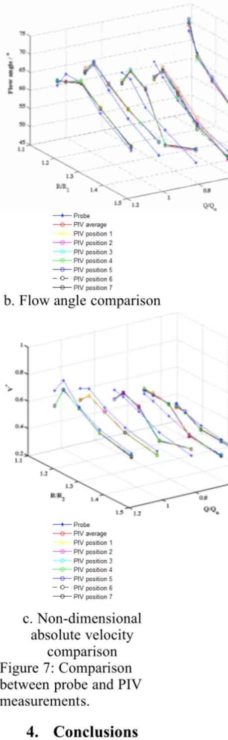
experimental setup, and result interpretations can be found in the reference paper [19]. The experimental procedure allowed the determination of the mean absolute velocities for up to 7 impeller angular positions relative to diffuser vanes, as shown in Figure 7a. Moreover, the time average values were plotted in Figure 7 for different locations inside the diffuser channel along
the radius that
corresponds to probe measurement locations 19 to 23 (see Figure 3). This method calculates the averaged radial and tangential velocities first followed formula 5 and 6, and then computes the flow angle and absolute velocity, as shown in Figure 7. This paper presents only the comparison at mid-span due to space constraints.
7 1 7 1 ( ) r r V d V d
(5) 7 1 7 1 ( ) ( ) ( ) u r u r V V d V V d
(6)Based on only the PIV results, the mean absolute angle and velocity distribution along the diffuser channel is constant no matter the
impeller blade position and flow rate values. This result is due to the fact that unsteady effects from the impeller relative position with the vane diffuser channel almost vanish in the main flow considering time average values of velocity components that are going to be compared with the probe measurements. However, it does not mean that this unsteady flows character has no action on the turbulence itself. Probe measurement results agree with PIV ones, mainly downstream from point 21. At the front of the diffuser channel, probe measurements do not correctly fit the PIV ones. This incorrect fit may be due to the possibility that flow structure may be more tridimensional inside the diffuser channel according to strong incidence angle gradients along the diffuser width (as seen in Figure 6a), which may create high axial velocity gradients between the pressure and the suction sides of the diffuser channel; these gradients cannot be measured by the probe itself. At high flow rates above the vane diffuser design flow rate, probe measurement values are always a little lower than the PIV values, which might be caused by the flow separation area and turbulence effects.
a. Scheme of the impeller positions
b. Flow angle comparison
c. Non-dimensional absolute velocity
comparison Figure 7: Comparison between probe and PIV measurements.
4. Conclusions
Detailed mean flow characteristics have been measured at different flow rates to analyze the mean inlet flow conditions of a vane diffuser of a centrifugal pump model that works with air. The initial conditions outside the impeller were used to process mean flow characteristics analysis, given by combining independent impeller performance measurements and 5
efficiency from URANS calculations. Local probe measurements inside the vane diffuser were also compared with PIV measurements.
The results show that the flow could be considered steady no matter the relative position of the impeller is as long as concerning overall diffuser performance. This finding allows analysis and evaluation of the pressure recovery of the vane diffuser part with inlet conditions coming from the impeller for all five mass flow rates. Static pressure evolutions seem to be better for low flow rates. However, care must be taken on the local absolute initial velocity gradients from hub to shroud to ensure a complete analysis of the flow inside the vane diffuser itself. The pressure recovery coefficients of the vane diffuser were compared with ideal theoretical ones for all flow rates. The difference between theoretical and real values indicates that the best pressure recovery factor is obtained near the design point of the diffuser that corresponds to the reduced flow rate value
Q/Qn= 0.8.
Acknowledgements
The researchers wish to thank CNRS for their financial supports. The authors also gratefully acknowledge the financial support from China Scholarship Council. References [1] M. Sinha, J. Katz, Quantitative visualization of the flow in a centrifugal pump with diffuser vanes. part I: on flow
structures and turbulence, J. Fluids Engineering, 122, pp. 97-107, 2000. [2] S. Guo, Y. Maruta, Experimental investigations on pressure fluctuations and vibration of the impeller in a centrifugal pump with vaned diffusers, JSME
International Journal,
48(1), pp. 136-143, 2005.
[3] K. Majidi, Numerical study of unsteady flow in a centrifugal pump, Journal of Turbomachinery, 127, pp. 363-371, 2005. [4] K. M. Guleren, A. Pinarbasi, Numerical simulation of the stalled flow within a vaned centrifugal pump, Proceedings of the Institution of Mechanical Engineers, Part C: Journal of Mechanical Engineering Science, 218, pp. 425-435, 2004. [5] S.-S. Hong, S.-H. Kang, Flow at the centrifugal pump impeller exit with the circumferential distortion of the outlet static pressure, Journal of Fluids Engineering, 126(1), pp. 81-86, 2004. [6] G. Pavesi, G. Cavazzini, G. Ardizzon, Time-frequency characterization of the unsteady phenomena in a centrifugal pump, International Journal of Heat and Fluid Flow, 29, pp.
1527-1540, 2008.
[7] J. Feng, F. K. Benra, et al, Unsteady flow investigation in rotor-stator interface of a
radial diffuser pump,
Forsch Ingenieurwes,
74, pp. 233-242, 2010.
[8] G. Cavazzini, P. Dupont, et al, Analysis of unsteady Flow velocity fields inside the impeller of a radial flow pump: PIV measurements and numerical calculation comparisons, Proceedings of ASME-JSME-KSME Joint Fluids Engineering Conference, Hamamatsu, Shizuoka, Japan, 2011. [9] G. Cavazzini, G. Pavesi, G. Ardizzon, Pressure instabilities in a vaned centrifugal pump, Proceedings of the Institution of Mechanical Engineers, Part A, Journal of Power and Energy, vol. 225(7),
pp. 930-939, 2011.
[10]G. Wuibaut, G. Bois, et al, Optical PIV and LDV comparisons of internal flow investigations in SHF impeller, Int. J. of Rotating Machinery, pp. 1-9, 2006. [11]G. Wuibaut, P. Dupont, G. Caignaert, G. Bois, Rotor stator interactions in a vaned diffuser radial flow pump, Proceedings of the 22nd IAHR Symposium on Hydraulic Machinery and Systems. Stockholm, Sweden, 2004. [12]G. Wuibaut, P. Dupont, et al, PIV measurements at the outlet part of a radial flow pump impeller and the vaneless diffuser in design and off design conditions,
4th International Symposium on Particle Image Velocimetry, Göttingen Germany, 2001. [13]A. Atif, S. Benmandsour, G. Bois, P. Dupont, Numerical and experimental comparison of the vaned diffuser
interaction inside the impeller velocity field of a centrifugal impeller, Science China Technological Sciences. 54: 286-294, 2011. [14]G. Cavazzini, G. Pavesi, et al, Analysis of the rotor-stator interaction in a radial flow pump, La Houille Blanche, pp. 141-151, 2009. [15]G. Cavazzini, P. Dupont, et al, Unsteady velocity PIV measurements and 3D numerical calculation comparisons inside the impeller of a radial pump model, 10th European Conference on Turbomachinery, Lappenranta, Finland, pp. 15-19, 2013. [16]P. Cherdieu, P. Dupont,et al, Data reduction problems using a 3 holes directional pressure probe to investigate mean flow characteristics in the vaneless gap between impeller and diffuser
radial pump,
Proceedings of the 6th International
Conference on Pumps and Fans with Compressors and Wind Turbines,
Beijing, China, 2013.
[17] A. C. Bayeul-Lainé, P. Dupont, et al, Fluid Leakage effect on
analysis of a vaned diffuser of SHF, 15th International Symposium on Transport Phenomena and Dynamics of Rotating Machinery, Hawai, Honolulu, USA, 2014. [18]J. P. Barrand, G. Caignaert, et al, Synthesis of the results of tests air and water aimed at critical recirculating flow rates detections on the inlet and outlet of a centrifugal impeller,
La Houille Blanche, 5,
1985.
[19]A. Dazin, G. Cavazzini, et al, High-speed stereoscopic PIV study of rotating instabilities in a radial vaneless diffuser, Exp
Fluids, 51:83-93, 2011.