Science Arts & Métiers (SAM)
is an open access repository that collects the work of Arts et Métiers Institute of Technology researchers and makes it freely available over the web where possible.
This is an author-deposited version published in: https://sam.ensam.eu
Handle ID: .http://hdl.handle.net/10985/7975
To cite this version :
Marcin GOLABCZAK, Philippe JACQUET, Corinne NOUVEAU, Romain FLITI - Tribological investigations of TiC+a-C:H Coatings Manufactured on X38CrMoV5-1 Steel Using PVD Technology - Defect and Diffusion Forum - Vol. 334-335, p.97-104 - 2013
Any correspondence concerning this service should be sent to the repository
Tribological Investigations of TiC+a-C:H Coatings Manufactured on
X38CrMoV5-1 Steel Using PVD Technology
Marcin Golabczak
1,a, Philippe Jacquet
2,b, Corinne Nouveau
3,c, Romain Fliti
3,d 1 Technical University of Lodz, Department of Production Engineering, Stefanowskiego 1/15,90-924 Lodz, Poland
2 École Catholique Arts et Métiers-ECAM, 40 Montée Saint-Barthélemy, 69321 Lyon, France 3Centre Arts et Métiers, Rue Porte de Paris, 71250 Cluny, France
amarcin.golabczak@p.lodz.pl, bphilippe.jacquet@ecam.fr, ccorinne.nouveau@ENSAM.EU, dRomain.FLITI-4@etudiants.ensam.eu
Keywords: PVD method, Cathodic Arc Evaporation, TiC+a-C:H coatings, Tribological
investigations, Pin-on-disc test, Wear resistance.
Abstract. X38CrMoV5-1 steel is a typical tool steel commonly used in forging and plastic
moulding industry for production of ejectors, slides, dies, etc. In plastics moulding a lot of these parts sustain relative movement. Because of this, some seizing or micro-welding may appear, especially when lubrication is not used. For many years, the different types of protective coatings were developed to avoid such problems. Most of the obtained solutions relate to the manufacturing of low friction coatings obtained by different nitriding processes and by CVD or PVD methods. In this article, the friction coefficients and the wear resistances of TiC+a-C:H protective coatings manufactured on X38CrMoV5-1 steel samples by using PVD technology are studied. The investigations are based on tribometer tests in different temperature conditions. The process of deposition of PVD coatings was realized by using multisource, hybrid factory-scale equipment of type URM 079. This equipment allows for deposition of coatings by a physical method. The tribological tests were performed using a precision high temperature tribometer under ambient and high temperature conditions with a steel and corundum balls as a counter-samples. In this paper, the results of these tribological tests are presented. It is shown that the measured friction coefficient of steel samples with PVD coatings is significantly lower than the friction coefficient of uncoated steel. It is also shown that X38CrMoV5-1 steel samples with manufactured TiC+a-C:H coatings are characterized by a very low friction coefficient and high wear resistance.
Introduction
X38CrMoV5-1 steel (ASTM designation) is a very commercial hot working steel characterized by very good mechanical properties (high tensile strength, hardness, high abrasion resistance, high yield stress – 2200 MPa). For this reason X38CrMoV5-1 steel is widely used in various branches of industry e.g. in die casting and plastic forming, cf. [1]. Moreover, its abrasive wear resistance and hardness (especially in the surface layer) can be significantly improved through thermochemical treatments or by application of surface coatings (nitriding, CVD and PVD coatings) as well as by laser alloying of the surface with tungsten carbide [2]. Steel producers try to outdo one another in developing specialized grades of steel and treatments for them. In this paper, the technology of manufacturing of TiC+a-C:H protective coatings on X38CrMoV5-1 steel using PAPVD (Plasma Activated Physical Vapour Deposition) method [3-5] is proposed. Moreover, the tribological investigation concerning measurement of friction coefficient and wear resistance of manufactured coatings is presented. For the investigations the X38CrMoV5-1 steel samples from LaBoMaP-Centre Arts et Métiers de Cluny-France were used. The chemical composition (in wt%) of investigated X38CrMoV5-1 steel is: 0.42% C, 0.5% Mn, 1.2% Si, 5.5% Cr, 1.4% Mo, 0.3% V, Fe balance. The series of samples of 30 mm diameter and 2 mm thickness were made. The main requirement of the preparation process of samples for deposition TiC+a-C:H protective coatings is to obtain the solid surface layer with low roughness and devoid of all impurities. To this end, the technological process of preparation of the samples is elaborated by using a precision grinder-polisher machine.
All rights reserved. No part of contents of this paper may be reproduced or transmitted in any form or by any means without the written permission of TTP, www.ttp.net. (ID: 193.55.245.2, ECAM, Lyon, France-04/03/13,15:26:40)
Preparation of X38CrMoV5-1 steel samples for investigations
The polishing process of samples made of X38CrMoV5-1 steel was carried out using Phoenix Beta 2 (Buehler-Germany) dual platen grinder-polisher machine equipped with a Vector power head and applying Buehler abrasive materials and lubricants. Process stages of realized operations contained:
two-stage grinding of samples using BuehlerMet silicon carbide (SiC) abrasive paper P600 (grits size ø 26 µm)and P1200 (grits size ø 15 µm);
lapping of samples using medium hard woven silk cloth VerduTex and monocrystalline diamond suspension MetaDi (grains size ø 3 µm);
polishing of samples using soft synthetic pad ChemoMet and aluminium oxide (Al2O3)
final polishing suspension MasterPrep (grains size ø 0,05 µm).
The elaborated technological process ensures suitable preparation of the steel samples in the range of required roughness parameters. It also ensures proper purity of the samples. The surface of polished samples had a silver glossy colour and invisible tool marks.
Experimental apparatus and procedure
For deposition of TiC+a-C:H coatings on X38CrMoV5-1 circular steel samples the modified hybrid PVD Cathodic Arc Evaporation (PVD CAE) system was used. The process of manufacturing of these coatings was realized in the Institute of Materials Science at Technical University of Lodz by using multisource, hybrid factory-scale equipment of type URM 079. This equipment allows for deposition of coatings by a physical method, cf. [3-5]. It has two independent continuous arc power supplies with magnetic filtration of microdrop for production of metallic plasma (maximum discharge current 180 V), two pulsating carbon plasma power supplies (average pulse power 1 kW) and magnetron source (power 10 kW) with a flat circular target of 100 mm of dimension. This equipment allows for plasma cleaning of the surface by four independent ion guns (4 kW/100 mA) in argon atmosphere. In the range of high voltages the polarization voltage of substrate was controlled from 800-2500 V. In the range of low voltages it was controlled from 0-200 V. The nominal vacuum was below 1,0x10⁻⁴ Pa. The scheme of the vacuum chamber of PVD stand and its equipment is presented in Figure 1.
Ar, N2, C2H2, CH4, O2
To the pump unit Gas flow controllers Continuous arc power supply Ionic gun power supply Ionic gun power supply Pulsating carbon plasma power supply Continuous arc power supply Ionic gun power supply Ionic gun power supply Pulsating carbon plasma power supply Magnetron power supply Sample bias control unit Sample temperature control unit
Fig. 1. Scheme of arrangement of separate parts in the vacuum chamber of PVD Cathodic Arc Evaporation stand used for deposition of TiC+a-C:H coatings.
Microstructure of X38CrMoV5-1 steel samples with TiC+a-C:H coatings
For comparison of microstructure of uncoated X38CrMoV5-1 steel samples with microstructure of steel samples with TiC+a-C:H coatings the optical profiler WYKO NT 1100 (Veeco Instruments-USA) was used. The results of investigations are presented in Figure 2.
Fig. 2. Microstructure images of X38CrMoV5-1 steel samples: a) uncoated after polishing, b) with TiC+a-C:H coatings.
The results obtained here show that the surface layer of X38CrMoV5-1 steel samples with TiC+a-C:H coatings have a regular, smooth structure and lower average roughness parameters (Ra=0.08 μm) than uncoated samples (Ra=0.087 μm).
Tribological investigations of TiC+a-C:H coatings manufactured on X38CrMoV5-1 steel samples
Tribological investigations of TiC+a-C:H coatings manufactured on X38CrMoV5-1 steel samples were done by using computer-controlled pin-on-disk tribometer (CSM Instruments-Switzerland) with a heated sample holder and with applying steel (100Cr6) and corundum (Al2O3)
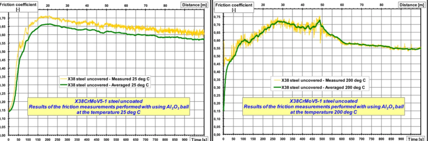
balls as a counter-samples. Tribological tests were conducted not only at ambient conditions (25°C) but also at a temperature 200°C because in some cases, moulds are heated in this range of temperature. Parameters of the friction coefficient test were as follows: load - 5N, frequency - 5 Hz, counter-sample ball radius - 6 mm, average velocity - 10 cm/s, distance 200-800 m. The results of friction coefficient measurements of uncoated X38CrMoV5-1 steel samples at 25ºC and 200ºC with using counter-samples made of different materials are presented in Figs. 3-4. Comparison of friction measurements of X38CrMoV5-1 steel with TiC-a-C:H coating at 25ºC and 200ºC with using counter-samples made of different materials are shown in Fig. 5 and Fig. 6.
Fig. 3. Friction measurements of uncoated X38CrMoV5-1 steel conducted at the temperature 25ºC and 200ºC using 100Cr6 ball as a counter-sample.
a) b) 0,00 0,10 0,20 0,30 0,40 0,50 0,60 0,70 0,80 0,90 1,00 0 500 1000 1500 2000 2500 3000 3500 4000 4500 5000 Friction coefficient [-] Cycles
X38CrMoV5-1 steel uncoated
Results of the friction measurements performed with using 100Cr6 ball at the temperature 25 deg C
0,00 0,10 0,20 0,30 0,40 0,50 0,60 0,70 0,80 0,90 1,00 0 500 1000 1500 2000 2500 3000 3500 4000 4500 5000 Friction coefficient [-] Cycles
X38CrMoV5-1 steel uncoated
Results of the friction measurements performed with using 100Cr6 ball at the temperature 200 deg C
Fig. 4. Friction measurements of uncoated X38CrMoV5-1 steel conducted at the temperature 25ºC and 200ºC using Al2O3 ball as a counter-sample.
Fig. 5. Comparison of friction measurements of X38CrMoV5-1 steel with TiC-a-C:H coating conducted at the temperature 25ºC and 200ºC using 100Cr6 ball as a counter-sample.
Fig. 6. Comparison of friction measurements of X38CrMoV5-1 steel with TiC-a-C:H coating conducted at the temperature 25ºC and 200ºC using Al2O3 corundum ball as a counter-sample
From the results presented above it follows that the measured friction coefficient of X38CrMoV5-1 steel samples with manufactured TiC-a-C:H coatings is significantly lower as compared with the steel samples without these coatings, especially at ambient conditions (25ºC). Moreover, it can be observed that the lowest values of friction coefficient both at 25ºC and 200ºC take place for corundum (Al2O3) ball as a counter-sample and even after a 800 meter test the
friction coefficient does not increase (Fig. 6). It means that TiC-a-C:H coatings manufactured on X38CrMoV5-1 are characterized by very high wear resistance.
0 10 20 30 40 50 60 70 80 90 100 0,00 0,05 0,10 0,15 0,20 0,25 0,30 0,35 0,40 0,45 0,50 0,55 0,60 0,65 0,70 0,75 0 50 100 150 200 250 300 350 400 450 500 550 600 650 700 750 800 850 900 950 1000 Distance [m] Friction coefficient [-] Time [s] X38CrMoV5-1 steel uncoated
Results of the friction measurements performed with using Al2O3ball
at the temperature 25 deg C X38 steel uncovered - Measured 25 deg C X38 steel uncovered - Averaged 25 deg C
0 10 20 30 40 50 60 70 80 90 100 0,00 0,05 0,10 0,15 0,20 0,25 0,30 0,35 0,40 0,45 0,50 0,55 0,60 0,65 0,70 0,75 0,80 0 50 100 150 200 250 300 350 400 450 500 550 600 650 700 750 800 850 900 950 1000 Distance [m] Friction coefficient [-] Time [s] X38CrMoV5-1 steel uncoated
Results of the friction measurements performed with using Al2O3ball
at the temperature 200 deg C X38 steel uncovered - Measured 200 deg C X38 steel uncovered - Averaged 200 deg C
0,00 0,05 0,10 0,15 0,20 0,25 0,30 0,35 0,40 0 50 100 150 200 250 300 350 400 450 500 550 600 650 700 750 800 Friciton coefficint [-] Distance[m] X38CrMoV5-1 steel covered with TiC+a-C:H coating
Results of the friction measurements performed with using 100Cr6 ball at the temperature 25 deg C
0,00 0,05 0,10 0,15 0,20 0,25 0,30 0,35 0,40 0,45 0,50 0,55 0,60 0,65 0,70 0,75 0,80 0 40 80 120 160 200 240 280 320 360 400 440 480 520 560 600 Friciton coefficint [-] Distance[m] X38CrMoV5-1 steel covered with TiC+a-C:H coating
Results of the friction measurements performed with using 100Cr6 ball at the temperature 200 deg C
Wear of the coating End of the test
0 50 100 150 200 250 300 350 400 450 500 550 600 650 700 0,00 0,02 0,04 0,06 0,08 0,10 0,12 0,14 0,16 0,18 0,20 0 500 1000 1500 2000 2500 3000 3500 4000 4500 5000 5500 6000 6500 7000 Distance [m] Friction coefficient [-] Time [s] X38CrMoV5-1 steel covered with TiC+a-C:H coating
Results of the friction measurements performed with using Al2O3ball
at the temperature 25 deg C X38 steel covered with TiC coating - Measured 25 deg C X38 steel covered with TiC coating - Averaged 25 deg C
0 50 100 150 200 250 300 350 400 450 500 550 600 650 700 0,00 0,02 0,04 0,06 0,08 0,10 0,12 0,14 0 500 1000 1500 2000 2500 3000 3500 4000 4500 5000 5500 6000 6500 7000 Distance [m] Friction coefficient [-] Time [s]
X38CrMoV5-1 steel covered with TiC+a-C:H coating Results of the friction measurements performed with using Al2O3ball
at the temperature 200 C
X38 steel covered with TiC coating - Measured 200 deg C X38 steel covered with TiC coating - Averaged 200 deg C
Wear rate of TiC+a-C:H coatings manufactured on X38CrMoV5-1 steel
For investigations of wear tracks of TiC+a-C:H coatings manufactured on X38CrMoV5-1 steel samples the optical profilometry was done by using the WYKO NT 1100 optical profiler (Veeco Instruments-USA). It allows for obtaining the profile of the track. The coatings wear tracks look like circular grooves. With the cross-sectional area of the track taken on several points it is possible to calculate the worn volume of the coatings and then to calculate the wear rate. In order to obtain a representative average, for measurements we have chosen 8 sections, one at every 45°. One multiplies the average section by the perimeter to have the volume:
(1)
where Vtrack is the worn volume (m3), r is the track radius (mm) and S is the average section (mm²). The wear rates of the coating and ball are calculated according to the equation [6]:
(2)
where: V is the worn volume (m3), w is the load (N) and s is the sliding distance (m).
Obtained results are depicted in Figures 7-8. However pictures of wear tracks of TiC+a-C:H coatings using optical microscopy are shown in Figures 9-10.
Fig. 7. The wear rate of the TiC+a-C:H coating manufactured on X38CrMoV5-1 steel with using 100Cr6 ball as a counter-sample: a) coating wear rate as a function of temperature, b) coating wear
rate as a function of sliding distance.
Fig. 8. The wear rate of the TiC+a-C:H coating manufactured on X38CrMoV5-1 steel with using Al2O3 ball as a counter-sample: a) coating wear rate as a function of temperature, b) coating wear
rate as a function of sliding distance.
0 5 10 15 20 25 30 35 40 0 25 50 75 100 125 150 175 200 225 250 C o a ti n g w e a r ra te ( 1 0 -6 mm 3/N m ) Temperature [ C] TiC-200 m TiC-800 m
Wear of TiC+a-C:H coating performed with using 100Cr6 ball a) 0,01 0,10 1,00 10,00 100,00 0 100 200 300 400 500 600 700 800 900 1000 C o a ti n g w e a r ra te ( 1 0 -6 mm 3/N m ) Distance [m] 25 C 200 C
Wear of TiC+a-C:H coating performed with using 100Cr6 ball
Wear of the coating End of the test
0 0,05 0,1 0,15 0,2 0,25 0,3 0 25 50 75 100 125 150 175 200 225 250 C o a ti n g w e a r ra te ( 1 0 -6 mm 3/N m ) Temperature [ C] TiC-200 m TiC- 800m
Wear of TiC+a-C:H coating performed with using Al2O3ball a) 0,00 0,05 0,10 0,15 0,20 0,25 0,30 0 100 200 300 400 500 600 700 800 900 1000 C o a ti n g w e a r ra te ( 1 0 -6 mm 3/N m ) Distance [m] 25 C 200 C
Wear of TiC+a-C:H coating performed with using Al2O3ball
b) b)
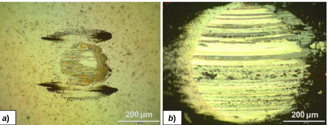
Fig. 9. Wear tracks of TiC+a-C:H coating manufactured on X38CrMoV5-1 steel sliding against 100Cr6 ball: a) after 800 meter test at 25°C, b) after 450 meter test at 200ºC.
Fig. 10. Wear tracks of TiC+a-C:H coating manufactured on X38CrMoV5-1 steel sliding against Al2O3 ball: a) after 800 meter test at 25°C, b) after 800 meter test at 200ºC.
The wear rate of TiC+a-C:H coating with using 100Cr6 ball as a counter-sample at the temperature 25°C and after 800 meter test is very low (0.085x10⁻⁶ mm3/Nm). However, at the temperature 200°C the wear rate rapidly increases to 2.899x10⁻⁵ mm/Nm after the 450 meter test (Fig. 7 and Fig. 9). The wear rate of TiC+a-C:H coating with using Al2O3 ball as a counter-sample
at the temperature 25°C and 200°C as well as after the 800 meter test is very low and its averaged values are respectively 0.167x10⁻⁷ mm3/Nm and 0.252x10⁻⁷ mm3/Nm (Fig. 8 and Fig. 10).
Wear rate of the counter-samples made of 100Cr6 and Al2O3 balls
The investigations of the wear rate of the counter-samples were done basing on the morphology of the balls scars with using optical microscope. The morphology of the balls scars gives information about the friction mode and the wear mode. The size of the scar allows for calculating the ball wear rate. The worn material of the balls is similar to a spherical cap.
The worn volume of the balls is calculated according to the equations [7]:
(3)
( ) or ( ) (4)
where: Vcap is the worn volume (m3), hcap is the height of the cap (mm), Rball is the radius of the ball
(mm) and rscar is the radius of the scar (mm).
a) 200 µm b) 200 µm
a) 200 µm b) 200 µm
Obtained results are presented in Figures 11-12. However pictures of wear tracks of 100Cr6 and Al2O3 balls using optical microscopy are shown in Figures 13-14.
Fig. 11. The wear rate of 100Cr6 ball used as a counter-sample: a) ball wear rate as a function of temperature, b) ball wear rate as a function of sliding distance.
Fig. 12. The wear rate of Al2O3 ball used as a counter-sample: a) ball wear rate as a function of
temperature, b) ball wear rate as a function of sliding distance.
Fig. 13. Wear scar of 100Cr6 steel ball sliding against TiC+a-C:H coating manufactured on X38CrMoV5-1 steel: a) after 800 meter test at 25°C, b) after 450 meter test at 200ºC.
0,01 0,10 1,00 10,00 0 50 100 150 200 250 B a ll w e a r ra te ( 1 0 -6 mm 3/N m ) Temperature [ C] TiC-200 m TiC-800 m
Wear rate of 100Cr6 ball used as a counter-sample in friction
test of TiC+a-C:H coating
a) 0,01 0,10 1,00 10,00 0 200 400 600 800 1000 B a ll w e a r ra te ( 1 0 -6 mm 3/N m ) Distance [m] TiC-25 C TiC-200 C b)
Wear rate of 100Cr6 ball used as a counter-sample in friction
test of TiC+a-C:H coating
0,000 0,005 0,010 0,015 0,020 0,025 0,030 0 50 100 150 200 250 B a ll w e a r ra te ( 1 0 -6 mm 3/N m ) Temperature [ C] TiC-200 m TiC-800 m
Wear rate of Al2O3ball used as
a counter-sample in friction test of TiC+a-C:H coating
a) 0,000 0,005 0,010 0,015 0,020 0,025 0,030 0 200 400 600 800 1000 B a ll w e a r ra te ( 1 0 -6 mm 3/N m ) Distance [m] TiC-25 C TiC-200 C b)
Wear rate of Al2O3ball used as
a counter-sample in friction test of TiC+a-C:H coating
Fig. 14. Wear scar of Al2O3 corundum ball sliding against TiC+a-C:H coating manufactured on
X38CrMoV5-1 steel: a) after 800 meter test at 25°C, b) after 800 meter test at 200ºC.
The wear rate of 100Cr6 ball used as a counter-sample in friction test of TiC+a:-C:H coating at temperature 25°C is very small after the 200 meter test (6.206x10⁻⁸ mm3/Nm) and after the 800 meter test decreases even to 1.777x10⁻⁸ mm3/Nm. It means that the 100Cr6 ball probably wears during the running-in and acting at the same time like a polishing leveled the roughness of the coating. Since the surface of the ball and the coating are very smooth, the friction coefficient decreases and the wear slows down. However at the temperature 200°C the wear rate of 100Cr6 ball rapidly increases to 4.080x10⁻⁶ mm/Nm after 450 meter test (Fig. 11 and Fig. 13). The wear rate of Al2O3 ball used as a counter-sample at the temperature 25°C is also very small after the 200 meter
test (2.628x10⁻⁸ mm3/Nm) and after the 800 meter test it decreases to 6.790x10⁻⁹ mm3/Nm. At the temperature 200°C the wear rate of Al2O3 ball also decreases. After the 200 meter test it is equal to
1.870x10⁻⁸ mm3/Nm, however after the 800 meter test it is equal to 7.870x10⁻⁹ mm3/Nm (Fig. 12 and Fig. 14).
Final remarks and conclusions
Investigations carried out in this paper have confirmed that PVD CAE method enables deposition of protective TiC+a-C:H coatings on X38CrMoV5-1 steel samples. Elaborated technological polishing process of X38CrMoV 5-1 steel samples ensures suitable preparation of their surfaces in the range of required roughness parameters. It also ensures proper purity of the samples. From the results it evidently follows that TiC+a-C:H coatings deposited on X38CrMoV5-1 steel samples considerably improve their tribological properties. It was shown that the measured friction coefficient of steel samples with PVD coatings is significantly lower than the friction coefficient of uncoated steel especially with using Al2O3 corundum ball as a counter-sample. Wear
tracks of TiC+a-C:H coating sliding against corundum ball are very small even after a 800 meter test and the wear of the coating is not observed. It means that TiC+a-C:H coatings are characterized by a very high wear resistance.
References
[1] M. Hernandez, et al.: Surf. Coat. Tech. Vol. 202 (2008), pp. 1935-1943. [2] M. Heinze: Surf. Coat. Tech. Vol. 105 (1998), pp. 38-44.
[3] M. Golabczak A. Konstantynowicz: DDF Vol. 297-301 (2010), pp. 641-649. [4] M. Golabczak A. Konstantynowicz: J. Nano Res. Vol. 16, 2011, pp. 29-35. [5] B. Wendler: Functional Coatings by PVD or CVD Methods (TUL, Poland 2011). [6] K. Holmberg, H. Ronkainen, et al.: Surf. Coat. Tech. Vol. 202 (2007), pp. 1034-1049. [7] E.P. Whitenton, P.J. Blau: Wear Vol. 124 (1988), pp. 291-309.
a) 200 µm b) 200 µm
Tribological Investigations of TiC+a-C:H Coatings Manufactured on X38CrMoV5-1 Steel Using PVD Technology