This is an author-deposited version published in: https://sam.ensam.eu
Handle ID: .http://hdl.handle.net/10985/11187
To cite this version :
Mohamed HADDAD, Laurent GUILLAUMAT - Flexural Experimental Analysis Coupled To An Acoustic Emission Study Of A Curved Sandwich Structures Made By Filament Winding Process -2016
Any correspondence concerning this service should be sent to the repository Administrator : [email protected]
M. Haddad and L. Guillaumat
FLEXURAL EXPERIMENTAL ANALYSIS COUPLED TO AN
ACOUSTIC EMISSION STUDY OF A CURVED SANDWICH
STRUCTURES MADE BY FILAMENT WINDING PROCESS
Mohamed HADDAD1 and Laurent GUILLAUMAT1
1Laboratoire Angevin de Mécanique, Procédés et innovation – LAMPA
Arts et Métiers ParisTech ENSAM – CER Angers 2, Boulevard du Ronceray – 49035 Angers Cedex 01 France
Email: [email protected] , Web Page: http://fr.linkedin.com/in/mohamed7haddad
Keywords: Composite Materials, Curved Sandwich Structures, Filament Winding, Flexural Analysis.
Abstract
Composite sandwich structures studied in this paper were developed for a cylindrical tanks of vacuum vehicles using glass-fiber/vinylester composite facing and different types of foam cores like PET, PU and 3D woven Fabrics. The main objective of a designer is to choose the appropriate materials constituting the structure and determine the respective thicknesses of skins and foam in order to resist to bending moment, shear and axial stresses induced by forces applied to the material components. Generally, their study is based on the sandwich theory and the selection of materials having the appropriate properties, depending on its application. The work presented in this paper aims to characterize some of these lightweight structures in three and four points bending, followed simultaneously by acoustic emission control study to provide additional expertise elements. Finally, a failure analysis of sandwich structures is made to identify the different cracking modes of the different candidate materials.
1. Introduction
Knowing that they are generally designed to support bending forces, sandwiches structures must meet other requirements such as thermal insulation, acoustic, etc. Basically, the choice of the type of sandwich depends on its application, like for structures or structural elements requiring high stiffness and strength, mainly to flexural loads, together with low specific weight [1, 2, and 3]. The combination used as an efficient structural component to support the axial or bending loads structures which consists of a low density core bonded between two small thickness skins of a more rigid material [4]. The high flexural performance is the major advantage of this type of multilayer material which requires additional information on its quasi static properties.
The Polyethylene Terephthalate (PET) and Polyurethane (PU) based foams in addition to foams with 3D woven Fabrics have numerous applications in diverse areas of engineering. In fact, high structural strength at low weight, excellent fatigue resistance, and very good temperature stability are the important factors that enable these materials to substitute more traditional core materials such as PVC or Balsa. For example, the closed cell structure of PET foams ensures minimal humidity absorption and keeps the risk of physical degradation very low. Their ability to recyclability makes its very attractive for applications with focus on “green aspects”. With the basic properties of being a thermoplastic, PET foams have wide processing possibilities. Having both thermoset and thermoplastic properties allows this type of foam to be easily thermoformed and thus tremendously extends the possibilities in design (3D-shape). Same as PET foams, PU based foams are extremely
M. Haddad and L. Guillaumat
low-weight hybrid core materials with mechanical properties that can be individually optimized. This offers a multitude of benefits for the production process. Likewise, 3D Fiberglass Fabrics are fiberglass structures, consisting of the bi-directional fabric woven together by vertical pillars. After being impregnated, 3D glass Fabrics have a superior property both mechanically and chemically. In combination with resin, it is particularly suited for being a core material in industries that heavily rely on factors such as weight, impact resistance, thermal insulation, acoustic damping, and high strength. When used in cylindrical tanks of vacuum vehicles, composite sandwich structures are mostly subjected to flexural loading [5]. Although much experimental and numerical works have been done on the flexure of sandwich materials but rather limited to flat structures and rarely concerns curved sandwiches. A number of researchers have studied the failure modes of sandwich structures in flexure [6, 7]. Triantafillou and Gibson [5] studied failure modes of sandwich beams with aluminum face sheets and a rigid PU foam core. Failure maps for various core densities and span to-depth ratios were constructed for face yielding, face wrinkling, core yield in shear, and core yield in tension and compression. Based on similar failure equations, a weight optimum design of composite sandwich structures was proposed by Yoshii [7]. A summary of design approaches to sandwich construction may be found in [8] while information on cellular solids is available in [9].
The present study examines the quasi-static mechanical behavior of curved sandwiches made by filament winding with PET, PU and 3D woven Fabrics foams, that include glass-fiber/vinylester composite skins, focusing on flexural deformation mechanisms. This investigation has considered the flexural behavior of sandwich structures with full coupling of skin–core interaction under three-point and four-point bending loadings. The focus of the study was to elucidate the deformation and failure behaviors in parallel with an acoustic emission study (AE) [10, 11]. In addition, the experimental results have been compared with the classical beam theory to ascertain the reliability of the investigations findings.
2. Experimental results and evaluation of the flexural behavior
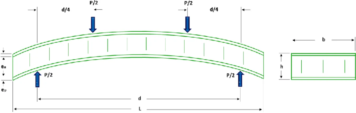
To characterize the sandwich materials manufactured for the structure of the cylindrical tank, we had to make curved specimens to represent the intended real structure. They were subjected to three and four bending test. The skins consist of several laminated and unidirectional plies of glass fiber /
vinylester resin in the directions 0° and 90° (total thickness of each skin ep = 4 mm). Different types of
foam cores with variable thicknesses between 6 and 25 mm were used, chosen for their drapeability. In accordance with the standard [12], the length of tested samples is 460 mm for a width of 70 mm (see Fig. 1). Furthermore, the influence of the span “d” between supports during the bending test was analyzed. The width of specimens was maintained for all tests for a length varied from 150 to 460 mm.
M. Haddad and L. Guillaumat
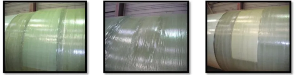
These samples of sandwich materials, presented in (Table 1), were manufactured using the filament winding process, with application of the real tension (~ 20N / yarn) on the glass fibers which form the two upper and lower skins, as figures shown below.
Figure 2. Sandwich materials manufactured using filament winding process by our industrial partner.
Then, each type of sandwich was cut into required specimen dimensions and tested according to the NF T-54 [12] standard. It was afterwards prepared and tested for its static flexural properties by three and four point bending test, on a Zwick-Roell universal testing machine equipped with a 100 kN force sensor. The test was conducted at a testing speed of 7,5 mm/min, while the load and displacement outputs were recorded using a built-in load and displacement cells in the testing machine. The loading pins and the supports had a diameter of 25 mm. To enrich our study, we highlight the correlations between acoustic signatures delivered by sensors placed on the specimens during mechanical testing (Fig. 3), and the nature of the damage observed at the macrostructural scale and critical damage thresholds.
Figure 3. Device of control and characterization of material damage: Acoustic Emission.
a) Preamplifiers b) Position sensors
Table 1. Description of different types of tested sandwich materials.
Specimen Type with : PET foam Gridded Type PET foam Standard Type PU foam with 3D glass bridges 3D glass Fabrics foam Description
A rigid PET foam (polyethylene terephthalate) with different densities, pre-cut as square grids (Grid) or Standard (thermoformable and easy to drape). This solution also allows the manufacture of curved shapes. It is compatible with all resins and existing production methods.
A hybrid material which has a PU foam based on a 3D structure of glass fibers stitched transversely to obtain optimized mechanical properties.
A sandwich material which has a 3D structure with woven glass fibers that includes two skins also achieved with same fibers of foam.
Real structure
M. Haddad and L. Guillaumat
The main idea is to establish the mechanical flexural behavior and discriminate, in real time, the different types of damage and failure in the composite to understand the involved mechanisms that
lead to the ruin of the structure [13, 14]. In order to properly compare the bending test results of the
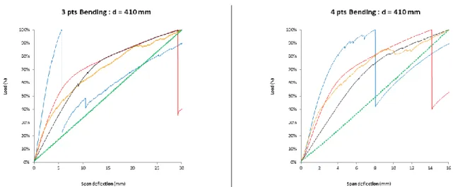
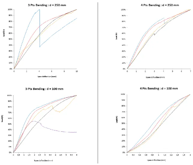
studied sandwich materials, the different curves have been normalized to their peak loads (Table 2). Total deflection W (mm) of all sandwich specimens is 80 mm in the case of 3-point bending and 60 mm for the 4-point bending. Thus, we observe evolutions of load-deflection relationships for the four types of sandwich structures presented in (Table 1). The specimens were loaded in three-point and four-point bending by varying the distance between supports between 100 and 410 mm in order to observe the evolution of the stiffness of each material. Note that the distance between supports varies in a range between 10 and 20 times the thickness of each specimen in accordance with the recommendations of the standard [12].
For distances between supports (d = 410 mm and 250 mm), a bi-linear behavior is observed up to the break with a sudden quasi-instantaneous loss of load for two sandwiches with PU foam and 3D glass Fabrics foam. Sandwiches with gridded and standard PET foams exhibit premature rupture compared to other types that suggest a greater stiffness. The charge increases progressively with the deflection until the moment when a sudden and fast fall of the load occurs.
When the distance between supports decreases up to 100 mm, the curves of normalized load - deflection show firstly a quasi-linear behavior of the specimens up to significantly high loads, then a nonlinear behavior up to a maximum load due to initial damages occurred roughly. For structural damage, cracking was observed in the skin in contact with the mid-span that drives the load. Then, the core reaches its elastic limit when the shear load increases. That maximum load is significantly greater than the value observed for large distances between supports, because the rigidity of sandwich materials is modified after the occurrence of cracking of the layers forming the two skins. So for every studied sandwich material, the limit of the elastic behavior is reached essentially when the foam reaches its elastic shear limit. Under these conditions, the materials will be solicited in transverse shear. We observed a few cases of shear failure of the core or delamination of core/skin interfaces. The increase of the density of the core (PET foams case) leads to an increase of the elastic limit and an improved stiffness of sandwich materials. This increase is greater while the distance between supports is low.
Table 2. Flexural test results in 3 and 4 point bending (normalized load-deflection relationship).
Sandwich with PET foam - Gridded h = 35 mm Sandwich with PET foam - Standard h = 35 mm Sandwich with PU foam with 3D bridges h = 20 mm
Sandwich with 3D glass Fabrics foam h = 16 mm Sandwich with 3D glass Fabrics foam h = 25 mm
M. Haddad and L. Guillaumat
Thus, there is some variability in sandwiches specimens cracking. The different failure modes that were observed are mainly caused by the different distances used between supports and by the bending mode (three or four point bending). Indeed, if the distance between supports is important, the sandwich skins are predominantly loaded in tension and compression, hence the rupture by compression of the upper skin. However, for shorter distances between supports, it is primarily the foam that is loaded in shear, from where we observe the appearance of shear failure mode (Fig. 4). For middle distances between supports, the structure is loaded in both tension / compression of the upper and lower skins, and shear of the foam that caused a random structure break.
M. Haddad and L. Guillaumat
3. Experimental investigation of acoustic emission signals and failure analysis
Thanks to their good mechanical response compared to other studied types of foams, we chose to complete a detailed study on PET foams using a real-time monitoring by acoustic emission (AE) in terms of amplitude, especially when the mechanical behavior of the structure varies nonlinearly, and in terms of location events to longitudinally locate the damage in each tested specimen. In addition, the acoustic emission analysis allows us to understand the contribution of different types of damage to the non-linear behavior.
3.1. Acoustic Emission – Amplitudes and cumulative counts
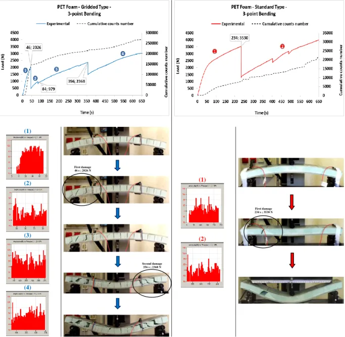
At our level, monitoring the amplitude of the acoustic emission signals collected at each step of damage gave the results presented hereafter. The corresponding value of force of the first observed damage is associated with an important decrease of it. However, this concept is better understood by the exploitation of acoustic emission results that shows an initial cumulative number of hits detected before the decrease of the force, in 3-point bending (Fig. 5).
(1) (2) (3) (4) (1) (2)
Figure 5. 3-point bending study of sandwich with PET foams by Acoustic Emission - Amplitudes. First damage 46 s ; 2026 N Second damage 356 s ; 2368 N First damage 234 s ; 3530 N
M. Haddad and L. Guillaumat
Compared to non-destructive testing of sandwich structures in mechanical tests, the figures illustrated in (Fig. 5), shows clearly that an acoustic activity starts well before a sudden important decrease of the elastic force limit indicating a major damage. More localized damage begins and progresses during loading to a level of instability that causes the sudden crack of the foam.
Through the histogram plots for each step of damage, we usually notice the existence of two distinct groups of acoustic emission signals with amplitudes varying between 50 to 60 dB (group A) and 90 to 100 dB (group B). So, based on the results found in the literature [15], the high amplitude signals correspond to fiber failure in the skin and / or local sandwich break in the foam, while those of low amplitudes are from different failures in the polymer matrix and fiber / matrix debonding in the skin.
3.2. Acoustic Emission – Location events
The location events issued from the acoustic emission signals, collected at each step of damage, gave the results presented hereafter (Table 3). For sandwich structures with PET foams, whatever is gridded or standard type, the different observed modes of failure are :
A. The local buckling of the upper skin that is observed for the three-point bending tests in most cases.
B. This local buckling is sometimes replaced by a shear failure of fibers in the upper skin that spreads by delamination between the skin and the foam.
C. For the three and four point bending, we observe a shear failure of the two types of PET foams propagating in delamination between the constituents of sandwich structure (skin / foam).
Table 3. 3-point bending study of sandwich with PET foams by Acoustic Emission – Location events.
PET foam - Gridded Type –
PET foam - Standard Type –
M. Haddad and L. Guillaumat 4. Conclusions
Failure modes of the different sandwich structures tested in bending were analyzed using two methods of three and four-point bending, using in parallel the non-destructive testing method: the Acoustic Emission (AE). We can notice that the results obtained experimentally are in a good fit with the characteristics of constituents measured in advance. But it should be noted that the filament winding manufacturing process may have an influence on the mechanical properties of the core, especially PET foams with/without grids, due to the presence of a certain quantity of absorbed resin or cast into the gaps and can remain in foams depending on the nature of manufacturing. However, the variability of observed results concerning the crack of the specimens is important. This is mainly due to local variations in the properties of each type of structure. A variability approach seems to be essential to better understand the failure of tested specimens.
Acknowledgments
The authors wish to thank the technicians of “l’Ecole Nationale Supérieure des Arts et Métiers (ENSAM d’Angers)” for their support regarding the manufacture of testing devices of curved samples and all our partners of FUI Project “SOLLICITERN”.
References
[1] D. HULL and TW. CLYNE. An introduction to composite materials. Cambridge University Press, Cambridge, 1996.
[2] EW. KUENZI. Minimum weight structural sandwich. US Forest Service research note FPL-086. F.P.L., Madison, 1965.
[3] D. ZENKERT. The Handbook of Sandwich Construction. s.l.: Emas Publishing, 1997.
[4] JM. BERTHELOT. Composite materials, mechanical behaviour and structural analysis. 3rd edn. TEC & DOC, Paris, 1999.
[5] TC. TRIANTAFILLOU and LJ. GIBSON. Failure mode maps for foam core sandwich beams. Mater Sci Eng 95:37–53, 1987.
[6] OT. THOMSEN. Theoretical and experimental investigation of local bending effects in sandwich
plates. Compos Struct 30:85–101, 1995.
[7] A. YOSHII. Optimum design of advanced sandwich composite using foam core. Adv Compos Mater 2(4): 289–305, 1992.
[8] D. ZENKERT. An introduction to sandwich constructions. Emas, London, 1995.
[9] LJ. GIBSON and MF. ASHBY. Cellular solids: structure and properties, 2nd edn. Cambridge University Press, Cambridge, 1997.
[10] E. ANDREWS and N. MOUSSA. Failure mode maps for composite sandwich panels subjected
to air blast loading. International Journal of Impact Engineering, 36(25), p. 418, 2005.
[11] I. DANIEL, E. GDOUTOS, K. WANG and J. ABOT. Failure modes of composite sandwich
beams. International Journal of Damage Mechanics, Volume 11, pp. 309-334, 2002.
[12] AFNOR NF T54-606. Structures sandwich à base de plastiques : Essai de flexion. [http://sagaweb.afnor.org/], 1987.
[13] A. CRAIG and A. NORMAN. Collapse mechanisms of sandwich beams with composite faces
and a foam core, loaded in three-point bending. Part I: analytical models and minimum weight design. International Journal of Mechanical Sciences, Volume 46, pp. 561-580, 2004.
[14] A. MANALO, T. ARAVINTHAN and W. KARUNASENA. Flexural behavior of glue-laminated
fiber composite sandwich beams. Composite Structures, Volume 92, pp. 2703-2711, 2010.