Science Arts & Métiers (SAM)
is an open access repository that collects the work of Arts et Métiers Institute of
Technology researchers and makes it freely available over the web where possible.
This is an author-deposited version published in: https://sam.ensam.eu Handle ID: .http://hdl.handle.net/10985/8610
To cite this version :
Jérôme PAILHES, Mohammed SALLAOU, JeanPierre NADEAU, Georges Michel FADEL Energy Based Functional Decomposition in Preliminary Design Journal of mechanical design -Vol. 133, n°5, p.051011-1 - 051011-10 - 2011
Energy based functional decomposition in preliminary design Jérôme Pailhès1, Mohammed Sallaou1,2, Jean-Pierre Nadeau1, Georges M. Fadel3
1TREFLE-ENSAM, Esplanade d’Arts et Métiers 33405 Talence Cédex, France; 2
ENSAM-Meknès, BP 4024, Meknès, Ismaïlia, Morocco;
3 CLEMSON UNIVERSITY, Clemson SC 29634-0921, USA.
Corresponding author : [email protected]
Abstract:
This paper presents an energy based approach to functional decomposition that is applicable to the top down design (system to subsystems to components) of mechanical systems. The paper shows that the main functions of convert and transmit are sufficient to focus on the "functional flow", or main energy flow resulting in the specific action sought as a result of the artifact being designed, and can be expanded upon at the lowest level, when looking for specific solutions based upon the energy and mass balances and the knowledge within the design team. This approach considers function as a transformation, and also fits the approach presented in TRIZ. The standard energy, material and signal flows are seen as forms of energy flows, and it is only their transformation and transmission that is sought. This simplified approach, coupled with an aspect of control, and interaction between a reference state and the artifact or between various components is sufficient to comprehensively describe the system that matches very nicely the value function approach of Miles. Furthermore, as these interactions can be considered as Artifact-Artifact Affordances when considering the artifact for either artifact interaction or within an environment, its relation to the user and to the reference state, it can be addressed during the design phase, in addition to the functions.
1. Introduction
Product design, a creative activity that begins with expressed needs and existing knowledge, results in a product definition that meets these needs and is industrially feasible. According to Suh, design is the transformation of functional needs into design parameters [1]. When analyzing the activity of designing, different approaches emerge, depending upon the working habits of the designers and the industrial context concerned. Building upon this notion, several research studies have looked at developing methods for organizing the design process and tools that can cope with the different tasks involved in this process. In their proposed synthesis of different design methodologies, for example, Tomiyama [2] discussed the gap between practical and educational usages. Our paper addresses this apparent disconnect and proposes a method that fills this gap.
Pahl and Beitz define the systematic design approach, breaking it down into four tasks: Product planning and clarifying the task, Conceptual design, Embodiment design and Detail design [2]. In our study we intend to adopt a systematic decomposition into design phases. We will use the term preliminary design, which encompasses both the conceptual design and embodiment design phases mentioned above.
As products become increasingly complex, it has become necessary not only to break down the design process into organized tasks [3], but also to break down the design problem into more easily manageable sub-problems [4, 5, 6]. This decomposition may be a domain-driven analysis of the product, according to Functional, Behavioral or Structural domains (FBS). Gero has studied interactions between these three domains based on an FBS model [7]. Using this decomposition he was able to exploit already existing and mastered knowledge when designing a new product. He also identified functions, basic sub-sets, and the physical behavior of components, all of which are well known in a given company and thus become design standards.
It has therefore become necessary to have this knowledge readily available for re-use, so as to improve and facilitate the design task. However, the difficulty lies in formalizing and structuring such knowledge. Several studies have attempted such formalization, particularly at standardizing the language used to define functions according to objectives [8, 9, 10, 11] by putting in place function bases that eliminate redundancy of terms while exhaustively spanning the domains of interest.
In this study we focus on structuring functions and components so that design choices can be made based on functional needs, leading to a definition of material solutions. The aim is to structure knowledge linked with functional, structural and behavioral views.
In order to devise tools to assist with preliminary design, one area of research consists of creating databases to provide the designers with the knowledge necessary for exploring various different solutions and for making the correct choices. Such databases include knowledge used to define product architecture based upon client needs. This knowledge is therefore associated with a functional view to identify the functions of the product and its components, with a structural view to select the components that constitute the product and determine their architecture, and with a behavioral view to pre-dimension the different design alternatives.
Defining the product in terms of functions is the point of departure for the design process [2, 3, 12, 13]. Regarding this functional view, several authors [8, 12, 14], in their various fields, have engaged in compiling databases of standard functions which can express functions exhaustively and precisely.
As Figure 1 shows, a function is defined as any system by which transformations of one basic element "material (m), energy (e) or signal (s)" into another occur within an artifact [15]. This definition is used to express functions at differing levels of functional decomposition [2, 9].
Figure 1 : Model of black box [15]
Functional modeling [9] is defined as a process of decomposing the global function of a product into sub-functions and these authors propose a standard vocabulary known as the functional base. This is a set of functions and flows with precise definitions which are combined in the form (verb + complement) to describe a sub-function [16]. The base combines the work of Stone et al [11] and Szykman et al [8]. The classification of flows into three categories (energy, matter, signal) is the same as that used by Pahl and Beitz [2]. The classes and the basic function categories and flows are given for instance in [17]. Note that this approach is typically more appropriate for reverse engineering applications when the artefact is being analyzed, and typically specific forms are associated with expressive functions at a level sufficiently low to allow this particular mapping.
The complete function and flow classification can be found in [16], which was obtained by reverse engineering. Many existing products were observed and analyzed in order to define terms and ensure the completeness of this base. The authors propose an exhaustive vocabulary for the functional description of products. They then define functional chains which can be used to describe the passage of all the flows present in the product. Heuristics are used to identify the number of unique modules required for functioning to be achieved. This indicator gives the maximum number of modules to use. The design concepts and product architecture are then determined by selecting standard components or components for redesign which can fulfill the functions of several modules. This methodology highlights modular design and optimizes the re-use of components already mastered within the company [11].
Suh has also put forward a methodology called Axiomatic Design to assist with component identification, by considering the functions that the product must fulfill [1]. The author uses functional decomposition at all levels and links functional requirements (FR) to design parameters (DP). He uses a top down method, starting from product and global function at level 0 and then decomposes functions and sub-sets at each of the lower levels. A systematic zigzag type of methodology is applied. The procedure requires moving step-by-step through the different levels of the product and the functional decomposition.
As our long term aim is to produce a taxonomy of knowledge [18, 19] structured into a knowledge base which brings together functions, components and physical models at different levels of decomposition, we intend to produce an energy based structure of functions adapted from the work of Hirtz and Suh [1, 16].
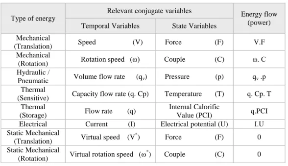
Although we are in agreement as to the distinction between energy, material and signal, the exegesis of this paper is that it is possible to express the principal or primary flow associated with conducting the main function(s) of the artifact in terms of an energy flow. This simplified process enables us to reconcile the design with physics based approaches in which input or output energy flow is expressed by energetic power, a product of two characteristic variables. As in thermodynamics, we can call these relevant conjugate flow variables. Indeed, one variable is relevant to temporal evolution and the other to energy potential. Certain variables of state
Energy Material Signal Function Energy Material Signal
are in fact variables of thermodynamic state (pressure, temperature); others give a generalized view, like strength or coupling [20]. While we could have used the chemical potential of the combustion power of fuel, we instead used the Internal Calorific Value (PCI), the most commonly used state parameter. The material flow, which is equivalent to the energy flow, is characterized by the product of a volume flow rate and its relevant conjugate variable, for instance pressure. Through our methodology, we propose to model material flows through a quantity which is homogeneous to an energy flow, and which is illustrated in Table 1. Indeed, for hydraulic or pneumatic energy (line 3), the material flow corresponds to an energy flow by unit of volume or mass according to the cases. Similarly, a signal may be an expression of energy flow even though the energy level is relatively weak.
In the case of static mechanical energy, there is no energy flow in the strict sense of the definition used in physics; as such, we differentiate between the two types (Table 1). Physicists have introduced the notion of virtual displacement (or speed) and suggest the principle of virtual power, now making it possible to produce a global system energy balance [21, 22].
Table 1 : Examples of relevant conjugate variables
Type of energy
Relevant conjugate variables Energy flow (power) Temporal Variables State Variables
Mechanical
(Translation) Speed (V) Force (F) V.F Mechanical
(Rotation) Rotation speed (ω) Couple (C) ω. C Hydraulic /
Pneumatic Volume flow rate (qv) Pressure (p) qv .p Thermal
(Sensitive) Capacity flow rate (q. Cp) Temperature (T) q. Cp. T Thermal
(Storage) Flow rate (q)
Internal Calorific
Value (PCI) q.PCI
Electrical Current (I) Electrical potential (U) I.U Static Mechanical
(Translation) Virtual speed (V
*) Force (F) 0
Static Mechanical
(Rotation) Virtual rotation speed (ω
*) Couple (C) 0
Based on these observations, we propose (Figure 2) a systematic view of the notion of energy transformation in functional terms.
Figure 2 : Energetic view of functional flow 2. Energetic approach
We next propose an energetic view based on TRIZ’s “law of completeness of system parts”, one of the eight “laws” of technology evolution [23, 24], which decomposes a system into specific entities. This law, which has been referenced not only for the design of mechanical systems, but also for software systems, policies, and other systems, enables us to focus on the essential minimum needed to describe a system. While this law may seem overly restrictive and may induce a belief that complexity does not exist in a design system, the recursive nature of the implementation can introduce significant complexity. We can then define a taxonomy on which to build a base of components based on energy, its transformation and transmission. This information, built in a knowledge base, is replicable at each analysis level. A method for constructing physical models, based on identifying the functional flow, would then be possible.
2.1. Identification of components from an energetic standpoint
Function
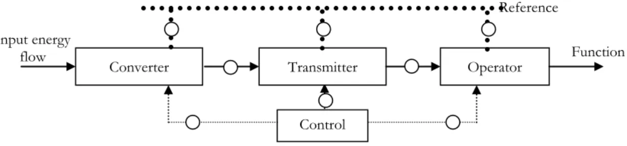
The problem of the systematic hierarchical structuring of a product has not been resolved. The product tree diagram is often seen as a specialty by specialty approach or a breakdown by level, using functional criteria [25]. By applying the “law of completeness of system parts”, as defined in the TRIZ method [23, 24] and taken up by Nadeau et al [26], for a given system it is possible to distinguish the four main elements essential for carrying out the required action or actions (Figure 3). These actions required are identified with service functions, also known as “fonctions de service” in French. The “law” states that the carrying out of an action may be reduced to four parts: engine, transmission, working element (operator) and control element. Each of these parts must attain a sufficient (or minimal) level of performance for the system to become operational. In particular, this “law” means that if one of the parts of the system fails, the system is not viable. In these specifications, we collect the set of applicable functions, each of which correspond to a situation and a particular requirement. Even if a system has multiple inputs or outputs, we consider that the primary functional flow of interest can be modelled as single input single output, even if it consists of several entities. We define the analysis of the system according to this context: the analysis of a weighted function leads to the identification of the functional flow necessary to the realization of this function. Action is carried out by the passage of a “functional” flow (to perform the action sought) which transmits input energy to the operator via the motor and the transmitter. This functional flow corresponds to an energy flow. According to the “law of completeness of system parts”, a system is more evolved (optimal) when it includes a control function carried out by a control component [24]. This decomposition must be done for all studied functions, each of which corresponds to a situation and a particular requirement. We define the analysis of the system according to this context: the analysis of a function leads to the identification of the functional flow necessary to the realization of this function. With this vision, we have only one entry, only one journey and only one exit for the considered functional flow. All relevant functions must be analyzed in an exhaustive manner. Note while additional flows can be added later, they are not considered primary.
Figure 3 : Law of completeness of system parts [24]
If we consider this law of completeness of system parts from an energetic perspective, each entity in the law should be translated into a characteristic energy form. We assimilate the action that the system must carry out to the function that this system must achieve. It uses an external resource, some type of energy, to carry out an action on an element that is external to the system. The law of completeness of system parts states that the carrying out of an action is the result of using an engine type element, which in energy terms, is a converter through which energy is transformed (Converter C). Again using energy terms, this energy then moves through a transmission element, which corresponds to a transmitter (Transmitter T). Next, an operator carries out the action ensuring that the action required by the system or the unit is conducted using output energy from the transmitter.
The output energy from the operator linked to the functional flow may be either:
a different type from the input energy (linked to the functional flow), in this case the operator is a transformer of energy (converter). (Example: for a wind-powered system, the “generator” (operator) which enables the mechanical energy to be transformed into electrical energy);
or:
the same type as the input energy (linked to the functional flow), in this case the operator is a transmitter. (Example: for an electric screw-driver, the “chuck + shank” (operator) enables mechanical energy to be transmitted to the screw).
The differentiation of the different types of energy can be seen in Table 1 where each line corresponds to an energy type. In all cases, the operator will be either a converter or a transmitter.
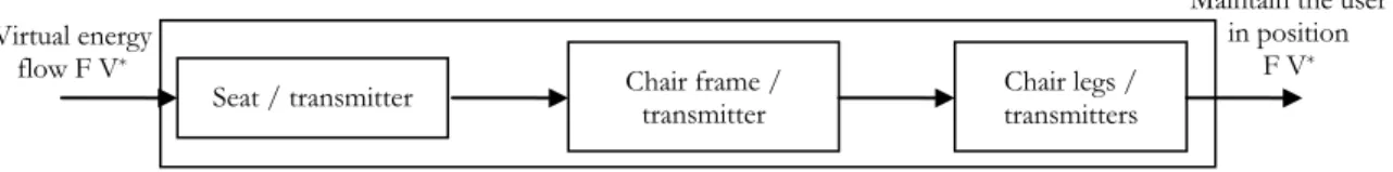
One particular case is the “flow” of mechanical energy in static conditions, where no real energy flow exists. One way of identifying the different components in such a case is to postulate the existence of a virtual displacement and velocity to demonstrate a virtual energy flow. We can then identify the components through which the virtual flow passes. The elements are exclusively transmitters if the flow that is present is a virtual mechanical energy flow. Figure 4 shows the structural decomposition of the use of a chair. The virtual movement, equivalent to the links, is a vertical displacement by the user in the absence of a chair, shown as V*.
Engine Transmitter Operator
Control
Energy Action
Functional flow Control flow
The virtual energy then passes via the chair, the frame and the chair legs to the ground. We can thus identify all the elements through which this energy flow has passed and define them as transmitters.
Figure 4 : Flow of virtual energy in the example of a chair 2.2. Analysis using the evolution of functional flow
An analysis of the main components of functional flows (Figure 3) shows that they can be defined according to two major groups: converters: if they change energy type and transmitters or if they retain the same energy type (Figure 5).
Figure 5 : Functional view of a “hydraulic pump” converter If we consider a hydraulic pump, it can be viewed from two functional angles:
- Function “transforming mechanical power into hydraulic power”: here we are dealing with an energy converter. The designer hopes to obtain a component with the best conversion rate of mechanical energy into hydraulic energy (functional flow), but some of the mechanical energy will deteriorate in the form of losses (e.g. leaks) or unwanted induced energy (e.g. heat). Only the main functional flow is shown in figure 6.
Figure 6 : Component as a converter
- Function “transporting a fluid”, here we are dealing with a transmitter for the primary energy. Transport may require energy input, and in our case this secondary energy is mechanical (Figure 7) and not shown in the figure at this stage. The “hydraulic pump” transmitter at the lower system level will then follow a structural organization identical to the one shown in figure 8, with new converters and transmitters.
Figure 7 : Component as a transmitter
The designer selects converter and transmitter type components so as to fulfill the required function, acting on a functional flow linked with the chosen solution.
Hydraulic pump
Transmitter Hydraulic energy
flow qv. p
Hydraulic energy flow qv. p
Hydraulic pump
Converter Hydraulic energy
flow qv.p Mechanical energy flow .C Converter Energy Type 2 e Energy Type 1 Transmitter Energy Type 2 e Energy Type 2
Seat / transmitter Chair frame / transmitter Chair legs / transmitters Virtual energy
flow F V*
Maintain the user in position
2.3. Structural organization (components)
Using the representation of the law of completeness of system parts in terms of energy it is possible to relate functions to sub-systems representing the different architectural elements of a system. Considering the TRIZ reference (Figure 3), we propose to replace the engine by the converter because this vision is more generic. The physical assembly of the components necessary to the functional flow (define Section 3.1 and 3.2) requires the introduction of supplementary components.
In order to control the functional flow, components of control/command are inserted to guarantee its quality. These elements can act indifferently on all previously identified components. The quality of the control depends upon the number of controlled components, on the localization of the controls and on the performance of the control system. The components must respect a defined spatial positioning with respect to each other and must be joined to a reference to guarantee this correct positioning.
To satisfy the migration of different flows between components, it is also often necessary to introduce components of interaction that permit to join the components or relate them to the reference.
We can therefore define (Figure 8):
Components linked with functional flows (converter, transmitter); Control / command components;
Reference system Interaction components.
Figure 8 : Energetic view of the law of completeness of system parts
Converter (C): Converts imported energy into energy that is usable by the other system components (input energy is type 1 and output energy is type 2). This involves a conversion of energy type. It can also provide or store energy as discussed in section 4.1.1.
Transmitter (T): Enables energy to be transmitted with no change in energy type (input and output energy are identical type 2). However, it may intervene by changing the relevant parameters of this energy for adaptation to the system constraints. For example, in a wind-powered system, the multiplier adapts the mechanical energy of the rotor to the generator by increasing rotation speed. Input and output energy are mechanical, however the conjugate variables of input and output power (couple and rotation speed) are different. Reference state (R): Related to the artifact under design. The reference state can be the floor upon which the artifact rests, a hand if the user has to hold the device, the housing or casing if designing the components of an artifact that have to fit inside some type of enclosure. Thus, this reference may be external to the system when considering a global reference at the top or system level, or internal to the system for a local reference at a given system or sub-system level.
Interaction components (CI): Makes it possible to link the different components and the reference state. The interaction components carry the flows generated at their interfaces. The interaction function may be achieved through an interaction component, or it may be integrated directly into the two components or the reference state. For example, the link between an engine and a speed reducer can be created through the intermediary of an external elastic coupling, which is then an interaction component, or the engine shaft can be assembled directly onto the reducer using a solution that is internal to the reducer. In this case there will be no interaction
Converter Transmitter Operator
Control Input energy
flow Function
Interaction component if necessary
components; they are often standardized with limited choices. When interaction components are linked to the reference state, the different components can be positioned in relation to the reference. This is an interaction component between a component and a reference from a higher level. This allows us to model interactions without having to revert to transformations.
Control – command (C/C): Ensures that the functions of the different components are properly carried out. Generally, the control/command elements ensure that the functional flows are able to pass in the most favorable conditions. Control/command can be decomposed, just as before, by identifying one or several converters, transmitters and interaction components.
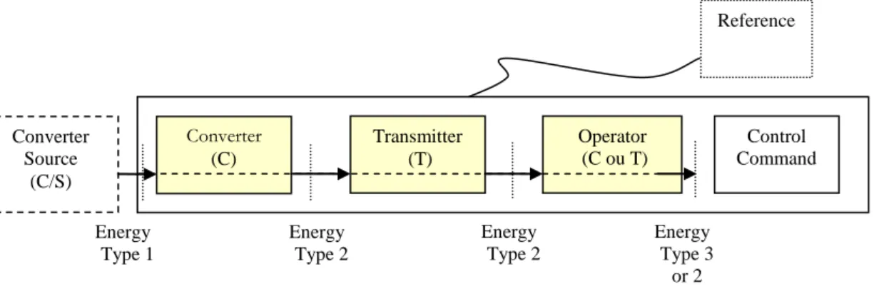
Figure 9 shows a systematic view of a product. This diagram can be reproduced at lower sub-system levels by specifying the decomposition of the converters. Transmitters can only decompose into transmitters. Interaction components should be specified at each level. The configuration in Figure 9 has no interaction components. The box around the converter/transmitter/operator/control-command entities represents a system boundary.
Figure 9 : Decomposition of a system and energy types 3. Function and component base
3.1. Function base adopted
Identifying a typology for the circulation and transformation of energy flows in a system will enable us to distinguish component functions (converter or transmitter), interactions, and control/command functions.
3.1.1. Component functions
The function of a component is defined according to the state of the functional flows of input and output energy. Table 2 shows the different classes of function identified based on action on an energy flow. Depending upon the input and output state, this flow may be supplied or stored or converted or transmitted. In the case of the store and supply functions, energy conversion is a conversion of external energy into potential internal energy and vice versa. For example, if water is stored in a water tower, when it is filling, hydraulic energy is converted into the potential energy of the water.
Table 2 : Classes of functions according to input and output states of the component functions Functions Entry flow Exit flow
Transmit Energy type 1 Energy type 1 Convert Energy type 1 Energy type 2 Convert/Supply No entry Energy type 2
Convert/Store Energy type 1 No exit
3.1.2. Component interaction functions
From a functional point of view, interaction between components has no effect on either the energy flows concerned or on their variables. The interaction function is to connect components together and enable energy to
Converter Source (C/S) Converter (C) Transmitter (T) Operator (C ou T) Reference Control Command Energy Type 3 or 2 Energy Type 2 Energy Type 1 Energy Type 2 The source may or may not exist
pass between them as freely as possible (with or without an interaction component). Obviously, there are losses which the designer will then try to eliminate or reduce as much as possible. Dealing with interactions is an essential task carried out by the designer, which not only enables him or her to be creative but can also generate a logic for prioritizing solutions. Energy transmission at the interaction level is ensured by creating a link between two components, typically using standard components, and the verb transmit is therefore used.
Maier and Fadel [27, 28, 29, 30, 31, 32, 33, 34] introduced the concept of affordances in engineering design. The theory of affordances was developed by the psychologist Gibson [35] and subsequently used by Norman [36] in the design of “usable” products. According to Gibson, “The affordances of the environment are what it
offers the animal, what it provides or furnishes, either for good or ill”. Thus, Artifact-User Affordances (AUAs)
were defined as the set of interactions between artifact and user in which properties of the artifact are or may be perceived by the user as potential uses. The artifact is then said to afford those uses to the user. Maier and Fadel [30] also extended this definition to Artifact-Artifact Affordances (AAAs) as being the set of interactions between two artifacts in which some properties of one artifact interact in some useful way with properties of the other. In the case described in the previous paragraph, the task of the designer is thus to consider AAAs, and design interactions to maximize the positive affordances and minimize the negative affordances present at those interaction points. Note that these affordances are not apparent to the designer until the artifact is physically embodied since the structure and the physical embodiment are what determine affordances. This approach augments the approach used in the French methodology of functional design. The French define function based on the Value Analysis of Miles, but broaden and qualify so that it may be used in different situations. In [37], “Principal Function” (Fonction principale) or “Use Function” (Fonction à valeur d’usage) is described as what the object is designed for, what its purpose is. Next is a set of “Service Functions” (Fonction de service) which are defined as expressing the expected action of the product on an element of the external environment to the profit of another element of that environment during a use phase of the product. They are thus a type of interaction in the same sense that affordances are a type of interaction.
3.1.3. Component/reference interaction functions
These functions are used to express links and positioning between the different components and a reference state. In design and from a component assembly point of view, different possibilities have to be analyzed and architectural choices made before implementing these functions. We associate the term link with the reference state to define component/reference state interactions.
Since interactions must be considered between the environment or the reference state and the artifact, and between the user and the artifact, additional AAAs and AUAs must be considered. Here, the Artifact User Affordances (AUAs) are most relevant since they dictate how the user interacts with the artifact.
3.1.4. Control/command functions
This function, which ensures that the system functions or the component functions operate properly, allows for any induced effects to be offset. The control function can be considered as a combination of a function specifying the use of information about flow (acquisition) with a command function acting on the artifact or the flow concerned (command). All these actions will be modeled using the verb control/command.
3.2. Defining the proposed function base
In this section we present a class of functions expressed as verbs. For each element identified at the structural level, we identify a specific list of verbs required to describe the functions fulfilled by a product.
A comparison of the functions in the Hirtz base with our proposed function classes [38] in Table 3 shows the functions selected in the energetic view of flows and the corresponding functions in the Hirtz database. While the class of functions we propose clearly incorporates all the verbs used by Hirtz, a loss of granularity is also evident and is described in Table 6.
In Table 3, the functions have been reorganized according to our design view. Specifically, the terms in the base are distributed and structured to make it suitable for use with our energy approach, and to allow the parallel placement of the functional and structural viewpoints. We note that control/command functions are realized by converters and transmitters.
Table 3 : Correspondence of functions according to the energetic view [38] Functions in the Hirtz database Primary class of functions adopted Primary
class
Secondary Tertiary Convert Transmit Link to
reference Control/ Comman d Convert Supply/ Store Branch Separate ● Divide ● Extract ● Remove ● Distribute ● Channel Import ● Export ● Transfer ● Transport ● Transmit ● Guide ● Translate ● Rotate ● Allow DOF ● Connect Couple ● Join ● Link ● Mix ● Control magnitude Actuate ● ● Regulate ● ● Increase ● Decrease ● Change ● Increment ● Decrement ● Shape ● ● Condition ● ● Stop ● ● Prevent ● ● Inhibit ● ● Convert Convert ● Provision Store ● Contain ● Collect ● Supply ● Signal Sense ● ● Detect ● ● Measure ● ● Indicate ● ● Track ● ● Display ● ● Process ● ● Support Stabilize ● Secure ● Position ●
Some interesting work has been done by Caldwell [39], in which he studied the frequency of use of all the verbs in the Hirtz database in a case study, with a set of 110 products taken from Stone’s functional base (Table 4). We note that only a few verbs are used with any great frequency (occurrence greater than 3%: transfer, import, convert, export, guide, change, actuate, store). The right-hand column shows the equivalent verbs used in our study. All the verbs we selected cover the domain described by Caldwell and are representative of the verbs
used most by Hirtz. Table 5 shows an analysis of frequency of use in the proposed base in relation to the products studied by Caldwell from Stone’s database.
Table 4 : Analysis of frequency of use in the Hirtz base [39] Function List significant Verb Results(>0.5%) Frequency in 110-product set Frequency percent in 110-product set [39] Equivalent Transfer 1236 27.3% Transmit Import 633 14.0% Convert store/supply Convert 447 9.9% Convert Export 429 9.5% Convert store/supply Guide 422 9.3% Link to reference Change 205 4.5% Convert Actuate 193 4.3% Control/convert Store 158 3.5% Convert store/supply Regulate 128 2.8% Control/convert Supply 100 2.2% Convert store/supply Stop 98 2.2% Transmit Distribute 93 2.1% Transmit Separate 70 1.5% Transmit Stabilize 69 1.5% Control Secure 53 1.2% Link to reference Transmit 46 1.0% Transmit Couple 45 1.0% Transmit Position 42 0.9% Link to reference Process 27 0.6% Convert/control Mix 27 0.6% Transmit
Why is this reduction in the number of verbs so sought after? Stone, Wood and researchers who use Hirtz’ functional base wanted to increase the number of verbs to give a more precise meaning to the function and eventually link generic solutions to certain functions. In energetic terms, such detail is not necessary until the lowest level is reached. At the principal level of structural decomposition, only a few functions are sufficient to describe energy development and behavior. The secondary class of verbs consists of general verbs very similar to verbs used in Hirtz et al., and Pahl and Beitz. They facilitate the design of general heuristics, guide the choice of architecture, and enable the definition of the next classes. The tertiary class only serves to clarify some distinctions among second level functions and may not be considered as a class in itself. The quaternary class is the lowest level of detail, and must be linked to a particular industry. Thus, we may refine the approach to particular industrial sectors and identify forms that accomplish these basic functions.
If the quaternary function verb is not present in the basis, then the designer can search for some synonyms. In the case where a synonym does not exist in the basis, and heuristics do not propose any viable solutions, the designer must complete the basis or must use creativity sessions to generate new solutions. These solutions however should be clearer at this level than at the top level of decomposition. If necessary, as the quaternary function verbs are linked to an industrial area, each user can add verbs to complete their own basis, and to specialize the data with the knowhow of the company. The realisation of industrial basis must be realised with respect to the logical structure proposed in the Table 6. This table shows an example of a base adapted for the field of mechanics, where each precise verb in the later classes refers to technological solutions that are known to, and mastered by, the company. These words are typically generated internally to the company and have a
precise meaning, typically translatable directly into a sub-system or component. This mapping was accomplished for a shoe manufacturing industry and is published in [40].
Table 5 : Analysis of frequency of use in the proposed base Function List
significant Verb Results (>0.5%)
Convert Transmit Link to
reference Control Convert Supply/Store Frequency percent in 110-product set 51.3% 35.7% 11.4% 8.6% 22.1% 29.2%
The problem for designers is the transition from functional analysis to the structural decomposition of the product. The aim is to structure this transition, given that there is no one-to-one mapping between the two views, functional and structural (hierarchical). Indeed, one component can fulfill several functions and vice-versa. By means of an energetic analysis, we propose a link between these two views by associating functions and components. Through functions linked to the functional flows, this analysis in terms of energy flow allows for an initial organization of the components, which will be completed when interactions and induced effects are analyzed.
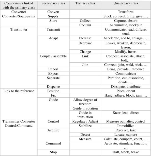
Table 6: Function and component classes Components linked
with the primary class
Secondary class Tertiary class Quaternary class
Converter Convert Transform
Converter/Source/sink Supply Stock up, feed, bring, give, …
Store Collect Capture, absorb
Contain Accumulate, stockpile
Transmitter Transmit Communicate, lead, diffuse,
send,
Adapt Increase Accelerate, add to, enlarge, … Decrease Lower, weaken, depreciate,
lessen,
Change Modify, invert
Couple / assemble Link Connect, associate, attach, bolt,...
Join Connect, join, weld, stick, …
Import Bring, provide, introduce
Export Communicate
Separate Partition, cut, dissociate,
divide, …
Disperse Dissipate, distribute
Link to the reference Position Place, orient
Fix Hang, adhere, block, jam, …
Guide Allow degree of freedom Guide in rotation
Guide in translation
Steer, lead, direct Transmitter Converter
Control/Command
Control Regulate / Adjust Measure out, alter, control
Stabilize Immobilize
Acquire Perceive, take
Detect Locate, capture
Measure Calculate, compare, count, …
Command Activate, stimulate, function,
…
3.3. Design process
The procedure we propose consists of two phases. The first phase is a functional analysis to determine the first or principal level functions of the product studied. This analysis employs the traditional tools of functional analysis using research into the external environments, life situations and interactions between these external environments and the product [37]. The second phase consists of a transition from the functional view to a physical structuring of the product using the analysis tools that are the subject of the present article. Lastly, the architectural definition of the product using a functional block diagram enables us to identify all the flows present (produced and induced). The flows identification is the starting point of the pre-dimensioning phase. We do not present this activity in this paper, however as it is the subject of further developments. The representation of the flows between elements permits to visualize the minimal functional path to achieve the functional conditions, and so to identify the key elements needed. The functional flows are linked to produced effects, with every component filling its function correctly in normal working conditions. From the perspective of safety, a component must assure the function for which it is designed without any of its elements deteriorating. Its dimensioning must be the result of the determination of the design variables that allow it to be capable of ensuring the necessary structural safety and thusly reducing possible induced effects. These induced effects can be harmful induced effects: effects generated by the realization of a function given of a component and degrading its working (example: wear, noise, heat….). For the pre-dimensioning phase, it is necessary to identify these induced flows.
Our method permits to select the necessary minimum elements to realize the function. So we prioritize the design activity using functional flows imposed by the service functions realization in a first step. In a second step, we take consider constraints and effects generated by the realization of function.
This method structures the design activity; we are currently developing an analytical logic of the design problem.
4. Example applied to a hair dryer
In this section, we apply the procedure to a hair dryer, an example that has already been studied many times [39, 41]. A functional decomposition of this hair dryer, taken from the literature, is shown in figure 10. Our approach is based on the principal function of the product studied. In this example, the principal function when the product is in use in an everyday situation is “to dry the hair”.
Figure 10 : Hair Dryer Function Decomposition Tree [41]
Based upon the principal function, we must then find components linked to the functional flow (Figure 11). The available energy used (input) is electrical energy; this is a constraint that is included in the specifications. Here, if designers lack ideas as to how to realise this function, they can use a creativity tool to find ways to dry the hair. For our example, as hot air (lower relative humidity) and air flow (to increase rate of evaporation) accomplishes this function, it is the solution that is usually adopted. We may not use our proposed base to find precisely the components of the structure (convert, transmit, operate (transmit), control) which are defined with verbs eventually linked to components names. We must therefore look for a converter that can transform the electrical energy into heat energy or into a form of energy compatible with being transported to where the hair is, to be converted into heat there. Next, we must define a transmitter that can transmit the heat energy to the hair; this is the role of the air flow generator (e.g. a fan and an air-flow guide). Finally, the operator is the element that will enable the air to be applied directly to the area to be dried, which is the role of the hot air diffuser (nozzle). It is therefore simple to represent the entire functional flow path via a converter and a transmitter unit. This unit must be maintained by the user’s hand in position relative to the reference state without causing any damage to
Dry Hair
Generate Air Flow Heat Air Flow Enclose Structure Control Flow
Guide Air Flow Convert Electricity to Rotation Convert Rotation to Flow Support Rotation Provide Handle Protect User Control Flow Provide Electricity
the hand. The link to the reference state is therefore all the parts related to system operation and safety, which ensure that the user is not burned or electrocuted. A good designer will always aim to achieve these different functions using the minimum number of parts possible. In our example, the outer casing of the hair dryer is the link to the reference state. Finally, control/command is achieved by acting on the different components linked to the functional flow. The operator regulates the amount of heat energy supplied by adjusting the converter (air temperature), adjusts the rate of hot air by interacting on the transmitter output and modifies air flow by selecting the nozzle that is best adapted for their purposes.
Figure 11 : Law of completeness of system parts applied to a hair dryer “Function: Dry the hair” Our analysis is then applied at different levels of decomposition. Considering the transmitter (air flow generator) in Figure 11, the function associated with this component is clearly to transmit. When we focus on the function “dry the air”, we can refine this function by using verbs from the secondary, tertiary and quaternary classes. If the air flow via natural convection is sufficient to generate a flow that dries the hair, then a simple transmitter will suffice and the verb transmit is appropriate. If, on the other hand, the flow of air is insufficient, then the transmitter must adapt the conjugate variables (pressure, air flow rate) by using extra energy. In our example, we need to adjust the air flow by increasing the air flow rate and accelerating it (Table 7). The main function required here is therefore “to accelerate air flow”. The presence of a converter is then necessary, which will use the available energy (electrical) to achieve this acceleration. In this case, we have two service functions, “functions de service”, Transmit air flow and Produce air flow.
Table 7: Extract from function and component classes Components linked
with the primary class
Secondary class
Tertiary class Quaternary class
Transmit Adapt Increase Accelerate, add to, enlarge, amplify, grow, raise, put up, intensify, rise, multiply, open Decrease Lower, weaken, depreciate, lessen,
drop, diminish, reduce
Change Modify, invert
The air flow generator can be viewed now from two functional angles similarly to the hydraulic pump presented earlier (Figures 6 and 7):
- Function “transmit air flow”, here we are dealing with an energy transmitter. Only the functional flow, the primary flow, (air flow) is considered for this function (Figure 12). The air generator flow is a transmitter for air flow (first service function).
Figure 12 : Component as a transmitter
Air flow generator
Transmitter Pneumatic Energy q
v. p Pneumatic Energy qv. p Converter Resistance Transmitter
Air flow generator External nozzle Transmitter
Control/Command
Switch + rheostat
Dry the hair Reference: Hand Reference: Hand Hot air Pneumatic Energy qv. p qv.p Hot air Pneumatic Energy qv. p Electrical Energy I.U Hot air Pneumatic Energy qv. p
- Function “produce air flow”, here we have an additional function. The generator transforms electrical energy into pneumatic energy. We are dealing with a converter (Figure 13). The functional flow (primary flow) is the flow situated between electric energy and air flow (Second service function).
Figure 13 : Component as a converter
The “air flow generator” at the lower system level then follows a structural organization identical to that shown in figure 14, with new converters and transmitters. We show the decomposition of the previous function Convert. Here, the converter is the electrical motor, the transmitter is the fan blades and the operator is the hair dryer casing and fan blade/air interaction. Control is managed by the operator and the speed controller (rheostat) which controls the motor. Note that there is no control at the transmitter and operator levels. It is not probable, for example, to modify the shape of the fan blades to control air flow. Note also that air or pneumatic energy does not enter the system as a principal flow at this time, but rather is acted upon by the principal energy flow. It is considered later when mass and energy balances are performed with select components responsible for these functions.
Figure 14 : Law of completeness of system parts applied to the function “Accelerate air flow”
For the function “transmit air flow”, we only have one element to operate the transmission, “casing +fan blade/air interaction (Figure 15).
Figure 15 : Law of completeness of system parts applied to the function “Transmit air flow”
The method, used in an industrial context for the design process of a shoe manufacture, has resulted in an innovative and entirely automatic process. A computer knowledge base, adapted to that industrial sector is under development, in order to capitalize the knowledge and to improve the design process. The basis is articulated in Table 6, the quaternary class grouping the professional terminologies and the know-how of the enterprise. [40]
Transmitter
Casing + fan blade/air
interaction Transmit air flow Reference: Body Pneumatic Energy qv. p Pneumatic Energy qv. p Converter
Motor Transmitter Blades
Converter Casing + fan blade/air interaction Control/Command Switch + variator Produced air flow Mechanical Energy C Mechanical Energy C Pneumatic Energy qv. p Electrical Energy I.U Reference: Hand Reference: Body
Air flow generator
Converter Pneumatic Energy q
v. p
Electric energy flow I.U
5. Conclusion
This paper presents an energy based view of functional decomposition that is applicable to the top-down design (system to subsystems to components) of mechanical systems. The standard energy, material and signal flows are forms of energy flows, and it is only that transformation and transmission of energy that is sought until the quaternary level. Contrary to the traditional verb specificity sought in the functional basis, the main functions of convert and transform are sufficient to focus on the "functional flow", or main energy flow resulting in the specific action sought as a result of the artifact being designed. The description of the main functional flow, which is fully compatible to a structural or form vision as presented in the literature (Suh), enhances the designer’s ability to translate function into a solution. Different functional types are identified (component functions, component interaction functions, component / reference interaction functions, control / command functions), that are attributes of a component basis or of specific solutions generated for specific industries. This decomposition is compared to the classical functional basis and an analysis of frequency of use in the proposed basis is realized. Our base of functions is coherent with the literature and incorporates all the verbs used in the classical bases. This simplified approach is sufficient to completely describe the system. The introduction of standard components in the functional base, according to main energy flow, generates the first elements needed to structure the design activity. The identification of components from an energetic standpoint is proposed. An example is proposed for the design of a hair dryer. We show that the analysis of the main energy flow permits to identify all the functions necessary, making it is possible to link this functional decomposition with the choice components at the lowest level. Current research to further this work is currently underway.
Acknowledgments
The authors wish to thank Drs. Jonathan Maier, Gregory Mocko and Mr. Benjamin Caldwell for their valuable comments on the draft of the paper.
References
[1] Suh N. P., (1990), "The principles of design", Oxford University Press, New York.
[
Erreur ! Source du renvoi introuvable.
] Tomiyama T., Gu P., Jin Y., Lutters D., Kind C., Kimura F., (2009), "Design methodologies :industrial and educational applications", CIRP Annals – Manufacturing Technology, 58, pp 543-565.[2] Pahl G. and Beitz W., (1996), "Engineering design – A systematic approach", 2nd edition, Springer-Verlag, London.
[3] Ullman D. G., (2003), "The mechanical design process", 3rd edition, McGraw-Hill Higher Education, New-York.
[4] Whitfield R. I., Smith J. S., Duffy A. H. B., (2002), "Identifying component modules", Seventh international conference on artificial intelligence in design, AID’02, Cambridge, United Kingdom.
[5] Holmqvist T. K., P., Persson M., L., (2003), "Analysis and improvement of product modularization methods: their ability to deal with complex products", Systems engineering, 6, pp. 195-209.
[6] Scaravetti D., Nadeau J.-P., Pailhès J. and Sébastian P, (2005), "Structuring of embodiment design problem based on the product lifecycle", International Journal of Product Development, Vol. 2, No. 1/2, pp.47-70, Indersciences Ed., Genève, Suisse.
[7] Gero J. S., (1990), "Design prototypes: a knowledge representation schema for design", AI Magazine, Vol. 11, No 4, pp 26-36.
[8] Szykman S., Janusz W., Racz and Ram D. Sriram, (1999), "The representation of function in computer – based design", Proceedings of ASME Design Engineering Technical Conferences 9/12-15, Las Vegas. [9] Stone R. and Wood K., (2000), "Development of a functional basis for design" Journal of Mechanical
Design, Vol. 122, No. 4, 2000, pp 359-370.
[10] Yang B. and Salustri F. A., (1999), "Function modeling based on interactions of mass, energy and information", Proceedings of the Twelfth International Florida Artificial Intelligence Research Society Conference, American Association for Artificial Intelligence.
[11] Stone R., Wood K., and Crawford R., (2000), "A heuristic method for identifying modules for product architectures", Design Studies, Vol. 21(1), pp 5-31.
[12] Kirschman C. F., Fadel G. M., (1998), "Classifying functions for mechanical design", Journal of Mechanical Design, vol. 120, n3, pp 475-482.
[13] Otto, K. and Wood K., (2001), "Product design: techniques in reverseengineering, systematic design, and new product development", Prentice-Hall, New York.
[14] Stone R., (1997), "Towards a theory of modular design", Thesis of Faculty of the Graduate School of The University of Texas at Austin, December 1997.
[15] Henderson M. R. and Taylor L. E., (1993), "A meta-model for mechanical products based upon the mechanical design process", Research in Engineering Design, Vol. 5, pp 140-160.
[16] Hirtz J., Stone R., McAdams D., Szykman S. and Wood K., (2002), "A functional basis for engineering design: reconciling and evolving previous efforts", Research in Engineering Design, Vol.13(2), pp 65-82. [17] Böhm M., Stone R., Szykman S., (2005), "Enhancing virtual product representations for advanced design
repository systems" Journal of Computer and Information Science in Engineering, Vol. 5(4), pp 360-372. [18] Sallaou M., Pailhès J., Nadeau J.-P., (2005), "Formulation d’une base de connaissance pour l’aide à la
décision en conception", 4ème Conférence Internationale Conception et Production Intégrée, CPI 2005, Casablanca, 9-11/11/05.
[19] Pailhès J., Sallaou M., Nadeau J.-P., (2007), "Knowledge base formulation for aided design tool", in Trends and Recent Advances in Integrated Design and Manufacturing in Mechanical Engineering II, edited By Serge Tichkiewitch, Michel Tollenaere et Pascal Ray, pp 231-244, edited by Springer Verlag.
[20] Callen, H. B., (1985), "Thermodynamics and an introduction to thermo-statistics", Second Edition, John Wiley & Sons, Ltd., N. Y.
[21] Torby B., (1984), "Energy methods", Advanced Dynamics for Engineers, HRW Series in Mechanical Engineering, United States of America: CBS College Publishing.
[22] Thompson F. and Hayward G. G., (1985), "Structural analysis using virtual work", Chapman and Hall, London.
[23] Altschuller G., (1984), "And suddenly the inventor appeared", Technical Innovation Center.
[24] Savransky S. D., (2000), "Engineering of creativity: Introduction to TRIZ methodology of inventive problem solving", CRC Press.
[25] Cavailles J., (1995), "Méthodes de management de programme", 2ème édition, DGA-Teknea.
[26] Doré R., Pailhès J., Fischer X., Nadeau J.-P., (2007), "Identification of sensory variables towards the integration of user requirements into preliminary design", International Journal of Industrial Ergonomics, Vol. 37, n° 1, pp 1-11.
[27] Maier, J. R. A. and Fadel G. M., (2001), "Affordance: The fundamental concept in engineering design", Proceedings of ASME Design Theory and Methodology Conference, Pittsburgh, PA. Paper no. DETC2001/DTM-21700.
[28] Maier, J. R. A. and Fadel G. M., (2002), "Comparing function and affordance as bases for design", Proceedings of ASME Design Theory and Methodology Conference, Montreal, Canada, Paper no.DETC2002/DTM-34029.
[29] Maier, J. R. A. and Fadel G. M., (2003), "On the complexity of the designer-artifact-user system", Proceedings of ICED 03, Stockholm, Sweden. August 19-21, 2003, Paper no. 1366.
[30] Maier J. R. A. and Fadel G. M., (2003), "Affordance-based methods for design", In: Proceedings of ASME Design Theory and Methodology Conference, Chicago, IL. Paper no. DETC2003/DTM-48673.
[31] Maier J. R. A., (2005), "Foundations of affordance based design", Ph.D. Dissertation, Department of Mechanical Engineering, Clemson University, Clemson, SC, 29634.
[32] Maier J. R. A., Fadel G. M., (2005), "A case study contrasting german systematic engineering design with affordance based design", In: Proceedings of ASME Design Theory and Methodology Conference, Long Beach, CA. Paper no. DETC2005-84954.
[33] Maier J. R. A., Fadel G. M., (2006), "Understanding the complexity of design", In: Braha D, Minai A, Bar-Yam Y (eds) Complex engineered systems: science meets technology. Springer, Berlin.
[34] Maier J. R. A., Fadel G. M., (2007), "Identifying affordances", Proceedings of ICED’07, Paris, France, August 27–30, Paper no. 591.
[35] Gibson J. J., (1979), "The theory of affordances", in The Ecological Approach to Visual Perception. Hopewell, NJ, Houghton Mifflin.
[36] Norman D. A., (1988), "The design of everyday things", New York, Currency Doubleday.
[37] AFAV, (1989), "Exprimer le besoin applications de la démarche fonctionnelle", Association Française pour l’Analyse de la Valeur.
[38] Sallaou M., (2008), "Taxonomie des connaissances et exploitation en conception préliminaire – Application à un système éolien", Thèse de Doctorat de l’école Nationale Supérieure d’Arts et Métiers. [39] Caldwell B. W., (2009), "An evaluation of function-based representation and information archival in
engineering design", MS Thesis, Clemson University, Clemson SC, USA.
[40] Ammar A., Scaravetti D., Nadeau J.-P., (2009), "Knowledge capitalizing and analyzing heart the design of manufacturing processes", Proceedings Third of International Congress Design Modelling and of Mechanical Systems, Hammamet (CMSM'09), Tunisia, March 16-18.
[41] Leung P., Ishii K., and Benson J., (2005), "Modularization of work tasks for global engineering," 2005 ASME International Mechanical Engineering Congress and Exposition, Orlando, FL, United States.
![Figure 1 : Model of black box [15]](https://thumb-eu.123doks.com/thumbv2/123doknet/7359261.213691/3.892.247.656.369.464/figure-model-black-box.webp)
![Figure 3 : Law of completeness of system parts [24]](https://thumb-eu.123doks.com/thumbv2/123doknet/7359261.213691/5.892.130.731.527.626/figure-law-completeness-parts.webp)
![Table 3 : Correspondence of functions according to the energetic view [38]](https://thumb-eu.123doks.com/thumbv2/123doknet/7359261.213691/10.892.98.776.130.1029/table-correspondence-functions-according-energetic-view.webp)
![Table 4 : Analysis of frequency of use in the Hirtz base [39]](https://thumb-eu.123doks.com/thumbv2/123doknet/7359261.213691/11.892.223.673.194.750/table-analysis-frequency-use-hirtz-base.webp)
![Figure 10 : Hair Dryer Function Decomposition Tree [41]](https://thumb-eu.123doks.com/thumbv2/123doknet/7359261.213691/13.892.114.784.693.877/figure-hair-dryer-function-decomposition-tree.webp)
