Science Arts & Métiers (SAM)
is an open access repository that collects the work of Arts et Métiers Institute of
Technology researchers and makes it freely available over the web where possible.
This is an author-deposited version published in: https://sam.ensam.eu Handle ID: .http://hdl.handle.net/10985/9041
To cite this version :
Zeineb CHIKHAOUI, Julien GOMAND, François MALBURET, PierreJean BARRE
Complementary use of BG and EMR formalisms for multiphysics systems analysis and control -In: Biennial Conference on Engineering Systems Design and Analysis (11; 2012: Nantes), France, 2012-07 - Advanced Manufacturing Processes; Biomedical Engineering; Multiscale Mechanics of Biological Tissues; Sciences, Engineering and Education; Multiphysics; Emerging Technologies for Inspection and Reverse Engineering; Advanced Materials and Tribology - 2012
Proceedings of the 11th Biennial Conference on Engineering Systems Design and Analysis ESDA2012 July 2 - 4, 2012, Nantes, FRANCE
ESDA2012-82318
COMPLEMENTARY USE OF BG AND EMR FORMALISMS FOR MULTIPHYSICS
SYSTEMS ANALYSIS AND CONTROL
Zeineb CHIKHAOUI
Arts et Metiers ParisTech ; CNRS, LSIS, 2 Cours des Arts et Metiers 13617 AIX-EN-PROVENCE - FRANCE
Julien GOMAND
Arts et Metiers ParisTech ; CNRS, LSIS, 2 Cours des Arts et Metiers 13617 AIX-EN-PROVENCE - FRANCE
François MALBURET
Arts et Metiers ParisTech ; CNRS, LSIS, 2 Cours des Arts et Metiers 13617 AIX-EN-PROVENCE - FRANCE
Pierre-Jean BARRE
Arts et Metiers ParisTech ; CNRS, LSIS, 2 Cours des Arts et Metiers 13617 AIX-EN-PROVENCE - FRANCE
ABSTRACT
In this paper, a complex multiphysics system is modeled using two different energy-based graphical techniques: Bond Graph and Energetic Macroscopic Representation. These formalisms can be used together to analyze, model and control a system. The BG is used to support physical, lumped-parameter modeling and analysis processes, and then EMR is used to facilitate definition of a control structure through inversion-based methodology. This complementarity between both of these tools is set out through a helicopter flight control subsystem.
Keywords: Bond Graph, Energetic Macroscopic Representation, modeling, control, and model federation.
INTRODUCTION
Mechatronic systems are very sophisticated products and are now necessary in several sectors, such as aeronautics and automotive industries [1]. For example, helicopters are very complex systems as they are composed of several subsystems with multiple interactions of different kinds and with many superposed fields of physics (mechanics, hydraulics, aerodynamics...). Designing such systems may be very difficult and requires a system approach to the design problem. An iterative design process of mechatronic systems is proposed in [2] with four phases and key elements of mechatronic systems modern design are presented in [1].
This work takes place on the first two phases of the design process of mechatronic systems [2]. It is more specifically focused on modeling and analysis of systems in order to obtain physical models, which are essential to study the behavior of the system. They should be available and are required in an early phase of the design, for example to evaluate the different controller solutions. Moreover, engineers usually need such models to modify the system or solve technical problems.
The usual modeling approach is based on transfer functions and use block diagrams for description purposes. This gives a mathematical view of the system and causes loss of the physical sense of dominant parameters in the system [2]. This is why engineers working in multidisciplinary fields, need complementary tools to support multiphysics system modeling in such a way as to have unified descriptions preserving dominant parameters and showing power transfer between elements of the system.
For that purpose, specific graphical tools offering powerful unified modeling formalisms have been designed to support and simplify complex multiphysics system analysis. Some of them have similar purposes of energetic graphical description, but each tool has been developed to highlight specific features. Therefore, a federative approach can be used to take advantage of these different features. This study is focused on two of these graphical tools: the Energetic Macroscopic Representation (EMR) [3] and the Bond Graph (BG) [4]-[5]. It shows the main similarities and differences between these modeling techniques in the analysis of a complex
system. As they have different features and purposes, these techniques can be used as desired and merged together in order to analyze a system.
In this paper, a helicopter flight control subsystem is described as an example, using both BG and EMR. The aim of this paper is to explain how both of these formalisms can be used together to facilitate physical, lumped-parameter modeling and analysis of theconsidered system in order to deduce control structures through inversion-based methodology [6]:
The first part is devoted to the description of the studied system. The second part deals with the basic principles of BG and EMR by showing their similarities and differences. Then, different steps showing cooperation between both formalisms are presented and explained. Finally, concepts of EMR inversion-based control are briefly presented.
I. STUDIED MULTIPHYSICS SYSTEM:
In order to control a helicopter behavior and path and thus fly in all directions, pilots had to control the rotor blade angles through mechanical drive trains without any assistance. Over time, additional devices have been installed in the control system in order to ensure comfort, safety and performance. This was exacerbated with the increase in the aircraft size. Basically, these devices provide the control effort required to prevent the pilot from applying too much effort to the stick to change the blade pitch. The set of such devices is termed helicopter flight control system [7]-[8].
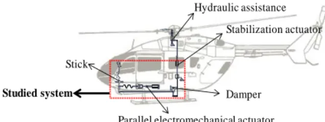
Several axes are considered in the helicopter flight control system, corresponding to the flight axes (Roll, Pitch and Yaw). Each axis is composed of the same devices which have several functions [7]-[8] (Fig. 1):
- A hydraulic assist system is placed at the end of each axis in order to provide the necessary control efforts. - A stabilization actuator is introduced in order to
stabilize the flight controls. It is fast but provides low stroke. Moreover, in the event of failure of the hydraulic unit, it takes over control of the control system.
- A parallel electromechanical actuator is used to create an anchor point for the flight controls, and release and move it. It detects when the pilot takes over control and creates a force feedback on the stick proportional to the stick movement around the anchor point. It then cancels this feeling at a constant angular position. It also ensures retrimming of the stabilization actuator when it comes at the end of stroke.
- A damper is inserted on each axis in order to damp the pilot's actions.
In addition to these devices, each axis is composed of rods, right-angle drives and idler bellcranks, which create friction.
Stick
Damper
Stabilization actuator Hydraulic assistance
Parallel electromechanical actuator
Studied system
Figure 1: Helicopter Control System.
The application described in this paper is part of a helicopter control system, from the stick to the stabilization actuator. The considered subsystem is shown in Fig. 1, and its multiphysics character is due to superposition of mechanical and electric fields. The main purpose is to show through this multiphysics subsystem the interest of complementary use of BG and EMR formalisms for modeling and analysis of a typical system.
II. BG- AND EMR-AIDED MODELING
This section presents the BG and EMR principles. Then cooperation between these formalisms is dealt with through the example of the studied electromechanical system.
1) Basic BG and EMR Principles
This part presents the basic BG and EMR principles by showing similarities and differences between them.
Both tools offer an energetic graphical description which simplifies the analysis of complex multiphysics systems. Both of them represent energy transmission in the system and highlight the power variables between components (effort and flow variables): the BG defines a bidirectional connection (with a half arrow) called power bond, representing the two power variables [9]-[10]. Concerning EMR, it is also based on the principle of action and reaction between connected elements, and describes the energy exchanged through bidirectional connections divided into two vectors: one for each power variable (effort and flow) [3]-[10].
Fundamental energy processes are defined by specific elements for both methodologies (see appendix). Depending on their power function and connections, four main types of elements can be distinguished [9]-[10]-[11]:
- Energy sources,
- Energy accumulation elements;
- Perfect conversion elements, without energy accumulation, and
- Perfect coupling elements for energy distribution. Energy losses are explicitly represented by a specific 'R' element in BG while they are included in (and thus associated with) energy storage elements of an EMR model. The latter is thus a slightly more macroscopic representation than a BG Model.
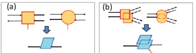
The main difference between both tools concerns causality (Links of cause and effect between elements). More specifically for energy storage elements, causality can be described in integral or in derivative form. Indeed, at a specific time ‘t’, integration of a time-dependent signal ‘u(t)’ can be known precisely because that requires its present and past evolution (Fig. 2.a). In contrast, derivation of a signal at the same instant ‘t’ requires knowledge of its future evolution (Fig. 2.b). In fact, the evolution of any physical parameter can only be the result of present and past events. Thus, the derivative operation is a mathematic concept, which is unsuitable for natural description of physical accumulative processes. And so, the natural causal link between input and output of energy storage elements can only be integral.
Figure 2: Illustration of causality concepts Integral causality (b) derivative causality.
In the BG methodology, assignment of causalities is made following a sequential causality assignment procedure with specific rules [9]. Integral causality is generally preferred but, in some cases, causal conflicts occur and lead to the use of derivative causality. Parts of energy storage elements are consequently represented with derivative causality, which implies potential simulation difficulties. In contrast to that, EMR imposes a natural representation of energy storage elements, i.e., only considering integral causality [3].
2) Complementary Use of BG and EMR:
This part deals with a complementary approach between BG and EMR. It shows how application of a structural analysis using BG methodology facilitates the obtaining of physical lumped parameters. Then, functional modeling using EMR is applied for easier deduction of control structures [11]. This approach is set out in three main steps:
Step 1: BG-Aided Structural Modeling
A structural analysis of the considered system is first conducted. It consists in observing the different components of the system in order to make a first version of modeling hypotheses. For example, some mechanical components are first
considered as rigid bodies, while others are assumed to be flexible.
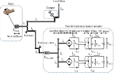
According to this structural and topological analysis of the system, a first model is obtained and represented in Fig. 2.
For redundancy reasons, the electrical part of this flight control subsystem is composed of two actuators with their own DC power source and driver. For the sake of simplicity, the two permanent magnet brushless DC motors are modeled as brushed DC Motors (DCM) powered by choppers. For each motor and associated power supply, two inductors (one for the stator windings, the other for the filter) and one capacitor (filter) are considered. These two actuators are mechanically coupled in parallel and participate to the flight control to ensure automatic pilot functions. From the mechanical point, inertias of both rotors (J1 and J2) and of the gearbox shafts (J3, J4 and J5) are
taken into account, as well as the stiffness of the physical spring
(Kactuator) which is designed is to provide a force feedback to the
pilot. The pilot is modeled as a mechanical source of speed acting on the control stick, considered as a flexible body (Kstick)
with inertia (J7). The remaining mechanical links between the
stick, the load and the parallel electromechanical actuators are considered as rigid, and thus modeled by inertias J8 to J10.
Figure 2: Model of the Considered Helicopter Flight Control Subsystem.
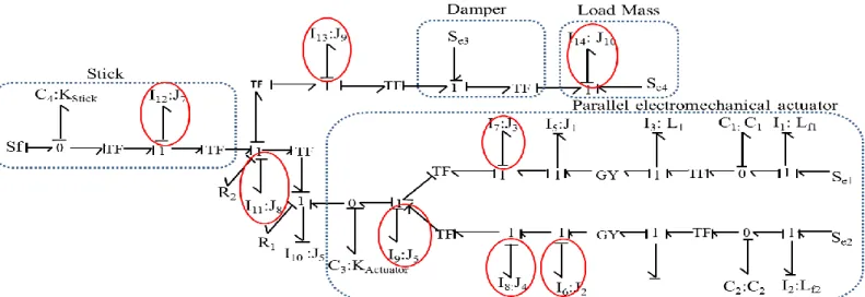
A representation of the model obtained using BG is then given in Fig. 3: Source elements (Se and Sf) are placed first; ports with same efforts are represented by 0-junctions and ports with same flows by 1-junctions. The storage elements (I, C) and dissipative elements (R) are placed and attached to the corresponding junctions. Finally, these elements are used in an object-oriented manner so as to create bond graphs. The obtained BG model gives a topological view of the system, according to the hypotheses chosen for this first modeling approach.
Figure 3: Structural Bond Graph Model of the Considered System. Causal strokes can now be assigned according to specific
rules, following a sequential procedure [9]. Integral causality is preferentially used but, when causal conflicts occur, derivative causality has to be assigned to some storage elements [12]. Elements requiring derivative causality are highlighted in Fig. 3.
Step 2: From a Structural Model to a Functional Model
The main objective of this method is to define a control structure of the system through model inversion techniques supported by EMR models. As the BG methodology allows the use of derivative causality, it gives a description that preserves the topological structure of the model proposed as a first approach for the system. However, using EMR methodology requires a model in which the energetic function of each storage element is considered, i.e., only considering integral causality. Such model is defined as a functional (causal) model [13].
This step aims at refining the modeling hypotheses in order to remove derivative causality from the structural model, leading to an energetic functional model so as to ensure compatibility with EMR methodology. Actually, occurrence of derivative causality points out parts of the model that have to be refined: in the example of the studied system, elements in derivative causality indicate difficulties related to the juxtaposition of several inertia modeling elements considered as rigid, i.e., without taking into account any transmission stiffness. Thus, additional studies (experimentation and/or numerical simulation) have to be conducted so as to increase knowledge about the dynamic behavior of the system, specially regarding components concerned by derivative causalities.
In order to eliminate derivative causalities and obtain a BG model in natural causality, two types of modification can be distinguished:
- The first type consists in adding a storage element, which increases the model order. When an ‘I’ energy storage element (representing inertia) is in derivative causality, that requires an inclusion of a ‘C’ energy storage element (representing capacity) between the two ‘I’ energy storage elements. In case of mechanical modeling, a spring must be added between two inertias, so the ‘I’ energy storage element initially in derivative causality will take integral causality. Conversely, when a ‘C’ energy storage element is in derivative causality, insertion of an ‘I’ energy storage element is required.
- The second type consists in concatenating similar energy storage elements, i.e., ‘I’ elements or ‘C’ elements, which preserves the model order. When there is juxtaposition of several similar elements in derivative causality, they can be concatenated with the nearest identical energy storage element taking an integral causality.
Modifications are made depending on the system model by analyzing the locations of energy storage elements having derivative causality (I and C) with elements having integral causality. To choose between the two types of changes previously presented, an in-depth analysis (experimentation, numerical simulation) must be performed.
For the considered system, the structural BG model initially obtained is modified so as to have a BG model in natural causality, as represented in Fig. 4. Referring to the physical system, flexibilities of different elements are considered as negligible. Thus, only concatenations of I energy storage elements are necessary and the system order is consequently preserved.
Figure 4: Bond Graph in Natural Causality of the Considered System.
Storage elements having derivative causality are eliminated through changes applied to the structural model in order to ensure compatibility with EMR. Structural approach applied to the system using BG gives a first topological modeling approach of the system and leads to a more detailed analysis focused on derivative causalities.
Step 3: BG-to-EMR Conversion
Finally, the last BG model obtained is converted to the equivalent Energetic Macroscopic Representation. Fig. 5 shows the corresponding representation.
Figure 5: Energetic Macroscopic Representation of the Considered System. For such conversion from BG in natural causality to EMR,
mapping operations are necessary and have to be written.
III. INVERSION-BASED CONTROL FROM EMR
EMR previously presented in Fig. 5 gives a synthetic view of the system according to causal relations between components and their energetic functions. This tool is thus defined as a causal modeling approach or functional modeling [13]. Due to this modeling approach, a control structure can be deduced from inversion methodology of the system. This step is not presented in this paper. Concepts of inversion-based control methodology are exposed as an introduction to future work.
Actually, controlling a process means defining the right input to be applied to the system in order to reach the desired trajectory of its output (Fig. 6), i.e., inversing the physical function of the process [6]-[11].
process
Input output
Control
Outputref(t)
Figure 6: Inversion Principle.
The inversion-based control methodology consists in applying this inversion principle to each element of the model (Fig. 5). Two types of inversion are necessary [3]-[11]:
- Elements without energy storage, i.e., conversion and distribution elements can be inverted directly by inverting the corresponding mathematical operation.
(a) (b)
Figure 7: Direct Inversion of Conversion Element (a) and Distribution Element (b).
- Elements with energy accumulation, for which direct inversion is not possible (direct inversion of an accumulation leads to derivative causality), need indirect inversion using a controller and measurements (Fig. 8). Such indirect inversion corresponds to the classical feedback controller.
Figure 8: Inversion of Accumulation Element.
These inversion rules are applied to each element along the chosen tuning path linking the tuning inputs to the output to be controlled. This leads to what is called "maximum control structure" [11]. During this procedure, all variables are assumed to be measurable. Then, simplifications and estimations of non-measured variables should be made in order to obtain a "practical control structure" [14].
CONCLUSION
A comparison between BG and EMR formalisms is given to highlight their different features and underline the possibility of cooperation between them, in order to support modeling of a system and then deduce control structures. Different steps showing this complementary approach are exposed and explained through the example of a helicopter flight control subsystem: First, a structural analysis of the system using the BG is applied to obtain a structural model. The latter can include elements with derivative causality that have to be eliminated in order toallow for conversion of the BG model to an EMR. Thus, derivative causalities are used as hints to point out where the structural BG model has to be refined or simplified through additional experimental and numerical studies, thus changing the initial modeling assumptions. The refined model is then converted to the equivalent EMR. Finally, model inversion with EMR is chosen to work on control structuring.
Future work will set out the EMR inversion-based control of the considered system and the necessary mapping operations for model conversion.
ACKNOWLEDGMENTS
This work was supported by the “Complex Mechanical Systems Dynamics” project - EADS Foundation - Arts et metiers Paritech - Ecole Centrale de Marseille.
REFERENCES
[1] W. Dieterle, “Mechatronic Systems: Automotive Applications and Modern Design Methodologies”, Annual Reviews in Control, Volume 29, Issue 2, 2005, pp. 273-277, ISSN 1367-5788, 10.1016/j.arcontrol.2005.05.002.
[2] J. van Amerongen, P. Breedveld, “Modelling of Physical Systems for the Design and Control of Mechatronic Systems”, Annual Reviews in Control, Volume 27, Issue 1,
2003, pp. 87-117, ISSN 1367-5788,
10.1016/S1367-5788(03)00010-5.
[3] A. Bouscayrol, B. Davat, B. de Fornel, B. François, J. P. Hautier, F. Meibody-Tabar, M. Pietrzak-David, “Multimachine Multiconverter System: Application for Electromechanical Drives”, European Physics Journal - Applied Physics, vol. 10, no. 2, May 2000, pp. 131-147.
[4] H. M. Paytner, “Analysis and Design of Engineering systems”, MIT-Press, Camb, MA, 1961.
[5] D. C. Karnopp, D. L. Margolis, R. C. Rosemberg, “System Dynamics - Modeling and Simulation of Mechatronic Systems”, Wiley Interscience, ISBN 0-471-33301-8, 3rd iss.
2000.
[6] P. J. Barre, A. Bouscayrol, P. Delarue, E. Dumetz, F. Giraud, J. P. Hautier, X. Kestelyn, B. Lemaire-Semail, E. Semail, “Inversion-Based Control of Electromechanical Systems Using Causal Graphical Descriptions”, IEEE-IECON’06, Paris, Nov. 2000.
[7] M. Martin, J. Gomand, F. Malburet, P.J. Barre, “Modelling and Control of an Effort Feedback Actuator in Helicopter Flight Control Using Energetic Macroscopic Representation”, IMAACA 2011, 5th International Conference on Integrated Modeling and Analysis in Applied Control and Automation, Rome, Italy, Sept. 12-14, 2011.
[8] T. KRYSINSKI, F. MALBURET, “Mechanical Instability”, Wiley. ISBN: 978-1-8482-1201-5, 2011.
[9] W. Borutzky, “Bond Graph Modelling and Simulation of Multidisciplinary Systems – An Introduction, Simulation Modelling”, Practice and Theory, Volume 17, Issue 1, January
2009, Pages 3-21, ISSN 1569-190X,
10.1016/j.simpat.2007.08.008.
[10] W. Lhomme, R. Zanasi, G.-H. Geitner, A. Bouscayrol, “Different Graphical Descriptions of Clutch Modelling for Traction Systems”, ElectrIMACS’08, Quebec (Canada), May 2008
[11] T. Letrouvé, A. Bouscayrol, W. Lhomme, “Influence of the Clutch Model in a Simulation of a Parallel Hybrid Electric Vehicle”, IEEE VPPC’09, Dearborn, USA, September 2009.
[12] P. J. Gawthrop, S. A. Neild, A. Gonzalez-Buelga, D. J. Wagg, “Causality in Real-Time Dynamic Substructure Testing”, J. Mechatronics, 2009, p1105-1115.
[13] Ph. Delarue, A. Bouscayrol, A. Tounzi, X. Guillaud, G. Lancigu, “Modelling, Control and Simulation of an Overall Wind Energy Conversion System”, Renewable Energy, vol. 28, no. 8, pp. 1159-1324, July 2.
[14] K. Chen, A. Bouscayrol, A. Berthon, P. Delarue, D. Hissel, R. Trigui, W. Lhomme, “Global Energetic Modelling of Different Architecture Hybrid Electric Vehicles”, IEEE Vehicular Technology Magazine, vol. 4, no. 2, June 2009, pp. 80-89.
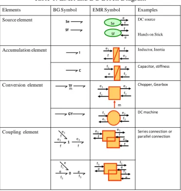
APPENDIX A
BG AND EMR BASIC ELEMENTS
Table 1 summarizes the main elements of Bond Graph and Energetic Macroscopic Representation. For each type of element, the BG and EMR symbols are explained by a physical example. Power variables are noted ‘e’ and ‘f’ for effort and flow variables, respectively. The product of both of these variables corresponds to the amount of power exchanged between two elements.
Table 1: EMR and BG Block Diagram
Elements BG Symbol EMR Symbol Examples
Source element DC source
Hands on Stick
Accumulation element Inductor, Inertia
Capacitor, stiffness
Conversion element Chopper, Gearbox
DC machine
Coupling element Series connection or
parallel connection Se Se Sf Sf I C e f e f e1 e2 f f f1 f2 e e TF m e1 e2 f1 f2 m GY e1 e2 f1 f2 0 f1 f2 e e e f3 e1 1 e2 f f f e3 e1 e2 e3 f f f e e e f1 f2 f3