THÈSE
En vue de l’obtention du
DOCTORAT DE L’UNIVERSITÉ DE TOULOUSE
Délivré par:
Université Toulouse III Paul Sabatier (UT3 Paul Sabatier)
Cotutelle internationale avec Universitat Politècnica de Catalunya
Présentée et soutenue par :
Ramón JEREZ MESA
le 2 Mars 2018
Titre :
Study and characterisation of surface integrity modification after ultrasonic
vibration-assisted ball burnishing
École doctorale et discipline ou spécialité :
ED MEGEP : Génie mécanique, mécanique des matériaux
Unité de recherche :
Institut Clément Ader, CNRS UMR 5312
Directeurs de Thèse :
Yann Landon
Université Toulouse III Paul Sabatier
Directeur
José Antonio Travieso Universitat Politècnica de Catalunya
Directeur
Gilles Dessein
École Nationale d’Ingénieurs de Tarbes Co-Directeur
Jury :
Mehdi Chérif
ENSAM de Bordeaux
Rapporteur
Guillermo Reyes
IQS, Universitat Ramon Llull
Rapporteur
Title: Study and characterisation of surface integrity modification after ultrasonic vibration-assisted ball burnishing
Author: Ram´on JEREZ MESA
Advisors: J. Antonio TRAVIESO-RODR´IGUEZ
Yann LANDON
Jordi LLUM `A-FUENTES Gilles DESSEIN
Date: February 2018
Abstract: This dissertation is an experimental research project into the mechanical effects of the ultrasonic vibration-assisted ball burnishing process on the surface integrity of surfaces ma-chined through ball-end milling.
First, a prototype able to perform the process is designed and characterised. Then, it is tested on AISI 1038 and Ti-6Al-4V surfaces, following an experimental campaign based on a Taguchi orthogonal array. The preload, number of passes, feed velocity, strategy and initial surface texture are included as factors. Results are analysed in terms of topological char-acteristics, residual stress and hardness. The original tex-ture proves to be the most influential parameter on all out-comes. Texture results show that the vibrations can enhance the roughness and texture results, as long as they have suffi-cient low initial amplitude.
The main conclusion arising from the study are different pa-rameter sets that can deliver the best results from the perfor-mance of the vibration-assisted ball burnishing process, ac-coding to a specific desired optimisation target.
Keywords: vibration-assisted ball burnishing; surface integrity; surface texture; residual stress; hardness; steel; titanium
Dissertation presented by Ram´on Jerez Mesa in partial fulfillment of the requirements for the degrees of
Doctor per la Universitat Polit`ecnica de Catalunya and
Acknowledgements
Fist of all, I would like to sincerely thank all professors that honour me by partici-pating of the evaluation of this dissertation: Irene Buj, Medi Ch´erif, Philippe Darnis, Giovanni Gomez and Guillermo Reyes.
Por supuesto, me gustar´ıa dar las gracias a mis directores espa˜noles, Jos´e Antonio Travieso y Jordi Llum`a, tanto por vuestra implicaci´on para con esta tesis, como por la amistad compartida, forjada en el d´ıa a d´ıa. Juntos, siempre llegamos.
Je voudrais bien aussi remercier mes directeurs franc¸ais Yann Landon et Gilles Dessein, ainsi comme mon encadrant Vincent Wagner. Vos aportations a cette th`ese ont ´et´e plus qu’enrichissant. Mais, surtout, je remercie sinc`erement de m’avoir ouvert les portes de chez vous pendant mes s´ejours en France. Je me rejouis de ces amiti´es impr´evues de l’autre cˆot´e des Pyr´en´ees.
Esta tesis es la culminaci´on de un camino que tom´e hace mucho tiempo, luego aparqu´e, pensando que de forma permanente, y al que volv´ı hace pocos aos sin haberlo esperado. Todo este proceso tiene diversos nombres propios asociados a ´el. En primer lugar, debo agradecer a los profesores de mi alma mater, la Universidad Polit´ecnica de Cartagena, que, seguramente sin saberlo, atizaron la llama de mi vocaci´on acad´emica: Jos´e Ram´on Navarro, con sus vectores deslizantes, y Mar´ıa Dolores Berm´udez y Ana Eva Jim´enez con sus l´ıquidos i´onicos. Por ´ultimo, ya en la Universitat Politcnica de Catalunya, debo agradecer a Toni Travieso, qui´en me regal´o la oportunidad de vivir esta maravillosa aventura.
I would not like to forget my colleagues in UPC, ENIT and UPS, who have been in different ways a support in this fascinating, however sometimes arid, trip of de-veloping a dissertation, and who have accompanied me when I was far from home. Giovanni, David, Eva, Joan, Silvia, Francesc Pozo, Marta, los Maneles y los Orioles,
and Cyrus Amini for his support for the finite element model. My gratitude also for Serge Tovar, Anis Hor, Abdallah Bouzid, and Mehdi Salem for their technical and op-erational support during my working days in Toulouse.
Por supuesto, quiero dedicar unas palabras a mis padres Juana y Ram´on, porque de peque˜no nunca me dejaron conformarme, y me ense˜naron el valor de esfuerzo para conseguir las metas. Sin este aprendizaje tan valioso, esta tesis no podr´ıa haberse cul-minado. Tambi´en a mi hermana Patricia, cuya confianza ciega en mi no tiene l´ımites. Und schließlich, danke, Hari f¨ur deine ewige Geduld und unbedingte Großz¨ugigkeit. Weil du immer f¨ur mich da warst, und weil du mich immer wieder auf den Boden der Wirklichkeit zur¨uckgeholt hast.
Summary
This dissertation is an experimental research project into the mechanical effects of the ultrasonic vibration-assisted ball burnishing process on the surface integrity of surfaces machined through ball-end milling. Due to the lack of commercial tools able to perform this process, the study includes firstly the design and characterisation of a prototype to that effect. An experimental analysis is then undertaken, applying the process to AISI 1038 and Ti-6Al-4V surfaces of high industrial and aeronautical value. The experimental campaign is designed based on a Taguchi orthogonal array that includes five factors, namely: preload, number of passes, feed velocity, strategy and initial surface texture. Results are analysed in terms of topological characteris-tics, residual stress and hardness, in order to identify and understand the impact of process parameters on surface integrity, to define the best parameters for performing the process and to assess the positive effects caused by the introduction of vibrations as a means of assistance.
Results reveal that the initial texture is the most influential parameter on all outcomes. Texture results show that the vibrations can enhance the roughness and texture re-sults, as long as they have sufficient low initial amplitude. Furthermore, only the preload and number of passes influence the results, with a pair of values being found in all cases that serve a threshold from which further plastic strain is detrimental for the final surface topology. In terms of residual stress, all parameters are influential in the results, especially the burnishing strategy, through which a certain component of the residual stress tensor can be adequately reinforced. Finally, the burnishing operation proves to modify the hardness of deep layers down to 0.5 mm, applying the vibration-assisted process. The main conclusion is that the optimal parameters for performing the process are different with regards to the optimisation objective. Some useful combinations are proposed for performing the process depending on the desired target.
Cette th`ese ´etudie les effets du processus de brunissage `a bille assist´e par vibra-tions ultrasoniques sur l’int´egrit´e surface des surfaces usin´ees par fraisage h´emisph´erique. Compte tenu de l’inexistence d’outils commerciaux capables de r´ealiser ce proces-sus, l’´etude d´ebute par la conception et la caract´erisation d’un prototype capable de l’ex´ecuter. Par la suite, une analyse exp´erimentale est men´ee, en utilisant le proc´ed´e sur les surfaces de deux alliages d’int´erˆet industriel et a´eronautique, AISI 1038 et Ti-6Al-4V. Pour cela, un plan d’exp´eriences est elabor´e `a base d’une matrice orthogo-nale Taguchi. Cinq facteurs sont inclus dans le mod`ele : la pr´echarge, le nombre de passes, la vitesse d’avance, la strat´egie de brunissage et la texture initiale de la surface pr´ealablement usin´ee. Les r´esultats sont ´evalu´es en termes de texture fi-nale, de contrainte r´esiduelle et de duret´e, pour identifier et comprendre l’impact de ce proc´ed´e et des param`etres op´eratoires sur l’int´egrit´e de surface, pour d´efinir les meilleurs param`etres `a appliquer pour chaque mat´eriau, et pour ´evaluer les effets positifs provoqu´es par l’introduction de vibrations comme moyen d’assistance. Pour cela, la notion d’int´egrit´e de surface est rappel´ee, voire red´efinie dans le cas de la texture de surface. En effet, les crit`eres classiquement utilis´es se r´ev`elent inaptes `a caract´eriser les surfaces obtenues, et une nouvelle m´ethodologie d’analyse des topolo-gies de surface est propos´ee.
Les r´esultats obtenus suite `a la r´ealisation du plan d’exp´eriences r´ev`elent que la tex-ture initiale est le param`etre pr´epond´erant. Les r´esultats de la topologie de face montrent que les vibrations peuvent am´eliorer la rugosit´e et la texture des sur-faces dans la mesure o`u l´etat de surface initial est suffisamment fin. Ensuite, seule la pr´echarge et le nombre de passes influencent le r´esultat, avec, dans tous les cas, un couple de valeurs limites `a partir desquelles les surfaces sont endommag´ees. Les r´esultats des contraintes r´esiduelles montrent que tous les param`etres influent sur le r´esultat final, en particulier la strat´egie de brunissage, avec laquelle la direction pr´ef´erentielle du tenseur de la contrainte superficielle peut ˆetre modifi´ee. Enfin, le brunissage montre une modification positive de la duret´e `a des couches d’environ 0,5 mm en appliquant le processus assist´e avec vibrations. Nous concluons que les param`etres de processus optimaux sont diff´erents en fonction de l’objectif d’optimisation, et que certaines combinaisons peuvent ˆetre utiles en fonction de ces objectifs.
Resumen
Esta tesis es un estudio experimental que versa sobre los efectos del proceso de bru ˜nido con bola asistido por vibraciones ultras´onicas sobre la integridad superfi-cial de superficies mecanizadas mediante fresa hemisf´erica. Dada la indisponibilidad de herramientas comerciales capaces de efect´uar este proceso, el estudio incluye en primer lugar el dise ˜no y caracterizaci´on de un prototipo a tal efecto. Posteriormente, se realiza un an´alisis experimental aplicando el proceso sobre superficies de dos alea-ciones de inter´es industrial y aeron´autico, AISI 1038 y Ti-6Al-4V, siguiendo un dise ˜no de experimentos parcial basado en una matriz ortogonal de Taguchi. Para ello, cinco factores son incluidos en el modelo, a saber: la precarga, el n´umero de pasadas, la velocidad de avance, la estrategia de bru ˜nido, y la amplitud de textura inicial. Los re-sultados se eval´uan en t´erminos de textura, tensiones residuales y dureza, para definir los mejores par´ametros a aplicar para cada material, y con el fin de evaluar los efectos positivos provocados por la introducci´on de las vibraciones como medio de asistencia. Los resultados revelan que la textura inicial es el par´ametro que define en mayor me-dida el estado de las superficies finales. Los resultados de textura evidencian que las vibraciones pueden mejorar en mayor medida la textura de las superficies objetivo, siempre que ´estas sean suficientemente finas. Adem´as, s´olo la precarga y el n´umero de pasadas influyen en el resultado, encontrando en todo caso un par de valores lim´ıtrofe a partir del cual las superficies se ven da ˜nadas. Los resultados de tensiones residuales muestran que todos los par´ametros son influyentes en el resultado final, especial-mente la estrategia de bru ˜nido, con la que puede modificarse la direcci´on preferen-cial del tensor de tensiones superfipreferen-cial. Finalmente, el bru ˜nido demuestra modificar la dureza positivamente hasta capas de aproximadamente 0,5 mm, aplicando el pro-ceso asistido con vibraciones. Se concluye que los par´ametros ´optimos de propro-ceso son diferentes en funci´on del objetivo de optimizaci´on, y deben definirse en base a dos variables de partida: el material objetivo y la textura que ´este presenta antes del proceso.
Aquesta tesi ´es un estudi experimental que tracta sobre els efectes del proc´es de brunyit amb bola assistit per vibracions ultras`oniques sobre la integritat superficial de superf´ıcies mecanitzades amb fresa hemisf`erica. Degut a la indisponiblitat d’eines comercials capaces d’aplicar aquest proc´es, l’estudi inclou en primer lloc el disseny i la caracteritzaci´o d’un prototip capa d’executar-lo. Posteriorment, es realitza una an`alisi experimental aplicant el proc´es sobre superf´ıcies de dues aliatges d’inter`es in-dustrial i aeron`autic, AISI 1038 i Ti-6Al-4V, seguint un disseny d’experiments basat en una matriu ortogonal Taguchi. Per aix`o, cinc factors s´on inclous en el model: la prec`arrega, el nombre d passades, la velocitat d’aven, l’estrat`egia de brunyit i la tex-tura de la superf´ıcie inicial. Els resultats s’avaluen en termes de textex-tura final, tensions residuals i duresa, per identificar i comprendre l’impacte d’aquest proc´es i dels seus par`ametres d’operaci´o sobre la integritat superficial, definir els millors par`ametres a aplicar per a cada material, i amb l’objectiu d’avaluar els efectes positius provocats per la introducci´o de les vibracions com a mitj`a d’assist`encia.
Els resultats evidencien que la textura inicial ´es el par`ametre que defineix en major mesura l’estat de les superf´ıcies finals. Els resultats de textura indiquen que les vibra-cions poden millorar en major mesura la rugositat i textura de les superf´ıcies, sempre que aquestes siguin suficientment fines. A m´es, nom´es la prec`arrega i el nombre de passades influeixen sobre el resultat, trobant en tot cas un parell de valors l´ımit a partir del qual les superf´ıcies s´on empitjorades. Els resultats de tensions residuals mostren que tots els par`ametres s´on influents sobre el resultat final, especialment l’estrat`egia, amb la qu`e es pot millorar la direcci´o preferencial del tensor de tensions superficial. Finalment, el brunyit demostra modificar la duresa positivament fins a capes d’aproximadament 0.5 mm de profunditat, aplicant el proc´es assistit amb vi-bracions. Es conclou que els par`ametres `optims de proc´es s´on diferents en funci´o de l’objectiu d’optimitzaci´o, i es proposen algunes combinacions que poden ser ´utils en funci´o del mateix.
Contents
List of Symbols xvii
1 Introduction 1
1.1 Motivations and antecedents . . . 1
1.2 Research contributions . . . 4
1.3 This dissertation in brief . . . 5
2 State of the art 9 2.1 General aspects of the burnishing operation . . . 10
2.1.1 An overview of burnishing tooling. . . 12
2.1.2 General description of ball burnishing parameters . . . 14
2.2 Experimental results on surface integrity after ball burnishing . . . 19
2.2.1 Geometrical parameters: surface roughness and texture . . . 22
2.2.2 Metallurgical parameters: hardness and metallography . . . 26
2.2.3 Mechanical parameters: residual stress . . . 28
2.3 Vibration-assisted ball burnishing. . . 33
2.3.1 Description of the acoustoplastic effect . . . 34
2.3.2 Experimental results of ultrasonic burnishing . . . 38
2.4 Objectives arising from the state of the art . . . 41
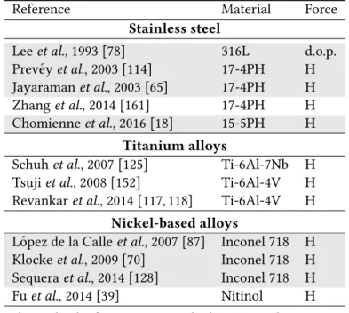
3 Design and characterisation of the VABB tool 43 3.1 Mechanical construction . . . 44
3.1.1 Force regulation unit . . . 45
3.1.2 Vibration transmission unit . . . 48
3.1.3 Force transmission unit . . . 53
3.2 Frequency measurement through acoustic emission. . . 53
3.2.2 Frequency of the ultrasonic signals recorded by AE . . . 57
3.3 Dynamometric characterisation . . . 58
3.3.1 Dynamometric experimental setup . . . 59
3.3.2 Quantification of the superimposed vibratory force . . . 61
3.4 Preliminary validation tests . . . 66
3.5 Synthesis . . . 71
4 Description of the experimental methodology 73 4.1 Experimental design . . . 74
4.1.1 Fractional design of experiments . . . 74
4.1.2 Factors included in the study . . . 76
4.1.3 Taguchi array . . . 78
4.1.4 Particular DOE arrays for the studied materials . . . 79
4.1.5 Unvaried process factors . . . 81
4.1.6 Results assessment through Analysis of Variance . . . 82
4.2 Measurement of the surface integrity parameters . . . 85
4.2.1 Acquisition of topological data . . . 85
4.2.2 Metallurgical characterisation of subsurface layers . . . 95
4.2.3 Residual stress measurement . . . 98
4.3 Material characterisation . . . 102
4.3.1 AISI 1038 alloy . . . 102
4.3.2 Ti-6Al-4V alloy . . . 104
4.4 Experimental execution. . . 107
4.4.1 Machining of the original surfaces . . . 108
4.4.2 Burnishing force measurement . . . 109
4.5 Recapitulation . . . 111
5 Experimental results and discussion 113 5.1 Geometrical parameter: surface texture . . . 114
5.1.1 AISI 1038 . . . 114
5.1.2 Ti-6Al-4V . . . 142
5.1.3 Comparison of topological results of AISI 1038 and Ti-6Al-4V . . . 155
5.1.4 Approach to the surface-ball interface through a finite element model . . . 161
5.2 Mechanical parameter: residual stress. . . 167
5.2.1 AISI 1038 . . . 167
CONTENTS
5.3 Optimal parameter sets according to texture and RS criteria: synthesis 186
5.4 Metallurgical parameter: hardness and metallography . . . 190
5.4.1 AISI 1038 . . . 190
5.4.2 Ti-6Al-4V . . . 195
5.5 Synthesis of metallurgical results . . . 198
6 Conclusions and perspectives 199 6.1 Future works. . . 202
6.2 Publications derived from this dissertation . . . 203
A L27 Taguchi arrays for experimental design 205 A.1 Compliance of the sufficient degrees of freedom condition . . . 209
A.2 Compliance of the orthogonality condition . . . 210
B VABB AISI 1038 texture figures 211
C VABB Ti-6Al-4V texture figures 217
D S/N ratios of residual stress ANOVA 223
List of Figures
1.1 Hemispherical milling of engineering surfaces. After Fontaine et al., 2006 [38]. a. Overview of a ball-end milled surface. b. Ball-end milling kinematic parameters and scheme of the process. . . 3 2.1 Schematic representation of the ball burnishing process. . . 10 2.2 Items and descriptors comprising the burnishing manufacturing system. 12 2.3 Classical burnishing tool configurations on lathe and milling machines.
After Murthy, 1981 [103] . . . 13 2.4 Special burnishing tool configurations. a. Milling & burnishing tool
[127] b. Center rest multi-ball tool [28] c. Multi-roller tool [141] d. Multi-ball tool [41] e. Adjustable roller tool [107] f. Multi–ball tool [140] 15 2.5 Force regulation systems in classical burnishing tools. a.
Depth-of-penetration tool [80]. b. Hydrostatic tool [119]. c. Spring-regulated tool [52] . . . 16 2.6 Experimental measure of force unevenness during a burnishing
pro-cess. After Lye & Leong, 1990 [91]. . . 18 2.7 𝑅𝑎 results of burnished INCONEL 718 surfaces. a. Influence of
bur-nishing pressure [70]. b. Influence of ball diameter [70]. c. Influence of burnishing pressure [128]. d. Influence of ball diameter [128] . . . . 25 2.8 SEM images of the surface microstructure of burnished specimens at
different pressure levels, and surface Vickers hardness. After L´opez de la Calle et al., 2007 [87]. a. Inconel 718. b. AISI P20 pre-heated steel 28 2.9 SEM images of 20Cr4 steel specimens. a. 200-N normal force. b.
400-N normal force. c. Subsurface shear instability caused by excessive plastic deformation. After Kuznetsov et al., 2015 [75] . . . 29 2.10 Microstructure and hardness of turned (𝑣𝑐 = 150 m/min, 𝑓 = 0.18
mm/rev, 𝑎𝑝 = 0.6 mm) and turned+burnished (250 N, 𝑛𝑏 = 1 pass,
2.11 a. Different residual stress scales 𝑙0,𝐼, 𝑙0,𝐼𝐼 and 𝑙0,𝐼𝐼𝐼. b. Examples of
sources of macro and micro residual stress states. After Withers & Bhadeshia, 2001 [157] . . . 31 2.12 Mechanical surface integrity results of ball burnished AISI 1045
spec-imens. After Avil´es et al., 2015 [4]. a. Depth dependence of residual stress. b. S-N fatigue diagram of burnished specimens. . . 32 2.13 Deep residual stress measured on Inconel 718. a. Influence of pressure.
b. Influence of ball diameter. After Klocke et al., 2009 [70] . . . 32 2.14 Comparison of residual stress measurement of ball burnished surfaces
through X-ray diffraction and incremental hole drilling. a. Results by Klocke et al. (2009) on Inconel 718 [70]. b. Results by Garc´ıa-Granada et al.(2017) [40]. . . 33 2.15 Effect of superimposed 800 kHz ultrasound on zinc crystal specimens
deformation. without, and - - - - with vibrations. After Blaha & Langenecker, 1955, [7] . . . 35 2.16 Stress reduction during compressive tests due to acoustoplasticity with
different amplitudes. a. Mild steel. b. Copper. c. Al-Al2O3alloy. After
Izumi et al., 1966 [62] . . . 36 2.17 Linear correlation between the vibration sensitivity, 𝑘, and work-hardening
coefficient, acoustic impedance and Young’s module. After Izumi et al. 1966 [62] . . . 36 2.18 Interaction of the burnishing force and the vibrations amplitude in
a. ultrasonic burnishing (after Marakov, 1973 [94]) and b. vibratory burnishing (after Pande & Patel, 1984 [109]) on mild steel specimens. . 39 2.19 Influence of burnishing force and frequency on a. surface roughness
and b. surface hardness, after Pande & Patel, 1984 [109]). . . 39 2.20 Deep residual stress profile comparison after conventional (CDCR)
and ultrasonic burnishing (UDCR). After Bozdana, 2008 [12]. . . 40 3.1 Structure of the ultrasonic vibration-assisted ball burnishing tool. . . . 45 3.2 Diagram of the FTU. a. Exploded view. b. Assembled parts and spring
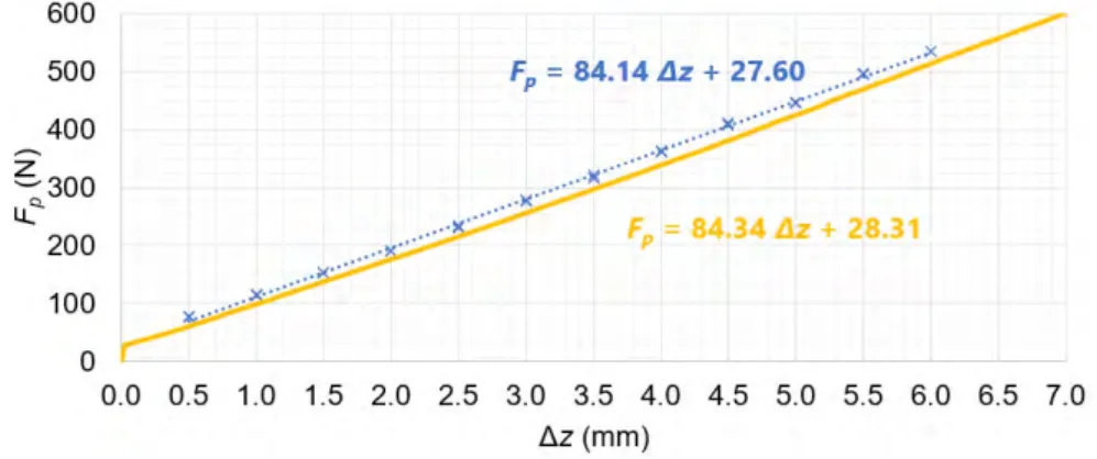
compression. . . 46 3.3 Calibration of the VABB prototype. a. Overview of experimental
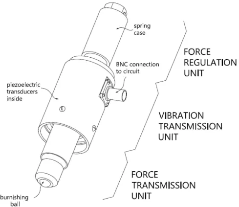
setup. b. Curve obtained by compression at 100-mm/min velocity. . . . 47 3.4 Stacked piezoelectric plates inside the VTU of the VABB prototype. . . 49 3.5 Frequency sweep and register of electrical impedance of the circuit
LIST OF FIGURES
3.6 Schematic representation of the force transmission unit. a. Detail of bearing balls on hemispherical track machined on the sonotrode tip. b.Assembled section of FTU components. . . 54 3.7 Experimental setup for the measurements through acoustic emission. . 56 3.8 Time history and frequency spectrum of signals registered the
bur-nishing line tests 270 N, 𝐴= 50% . . . 57 3.9 Experimental setup for the dynamometric measurements. . . 60 3.10 Comparison of calibration lines measured through continuous force
acquisition and Kitsler dynamometric measurements. . . 60 3.11 Sinus fit calculated for the recorded signal at 𝐹𝑝= 600 N and 𝐴 = 100%. 62
3.12 Half-cycle vibratory force variation, and extreme values, for different preload levels. a. 𝐴= 50%. b. 𝐴 = 100%. . . 63 3.13 Half-cycle vibratory force variation, and extreme values, for different
preload levels. a. 𝐹𝑝= 300 N. b. 𝐹𝑝 = 600 N. . . 65
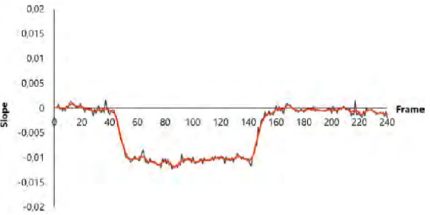
3.14 Preliminary burnishing imprints performed on a milled AISI 1038 sur-face. . . 67 3.15 Meshes I-IV defined on the tool for the image treatment routine. . . 68 3.16 Points composing the mesh of part I. . . 68 3.17 Raw and smoothed curves representing the slope presented by the
mesh of part I with a 90-N preload. . . 69 3.18 Angle and slope nomenclature related to the calculation of the relative
angle between tool sections. . . 70 4.1 Burnishing strategies included in the DOE and nomenclature of the
directions referenced in the text. . . 78 4.2 Linear graph associated to the L27 Taguchi array. Balls: factors. Lines:
interactions. . . 79 4.3 Schematic representation of the VABB (non-contoured yellow patches)
and NVABB (contoured blue patches) tests performed on a general workpiece and reference directions considered in this work. . . 81 4.4 Planned experimental tests represented on the three different
ma-chined 𝑆0. Striped patches: VABB tests. a. AISI 1038. b. Ti-6Al-4V. . . 83
4.5 Measurement of burnished track width on Ti-6Al-4V applying 150 N. . 84 4.6 Sampled 3D surface transformed into a height function. After Dong
4.7 Surface profiles and height distributions showing the effects of skew-ness and kurtosis. Top to bottom: positively skewed, negatively skewed, leptokurtic and platykurtic distributions. After Thomas, 1981 [146] . . 88 4.8 Main V parameters related to the bearing area curve, represented in
2D. Extrapolation to 3D can be easily visualised. . . 90 4.9 Evolution of some S parameters with respect to the sampling size. a.
𝑆𝑠𝑘 and 𝑆𝑘𝑢. b. 𝑆𝑞 and 𝑆𝑧10. . . 92
4.10 Overview of specimen positioned on the encapsulating machine plate. 95 4.11 Vickers microindentation hardness test scheme. . . 96 4.12 X-ray diffraction in a non-deformed crystal (left) and a deformed
crys-tal (right). . . 99 4.13 X-ray diffraction spectrum showing a diffraction peak at 2𝜃𝜓position,
with regards to the spectrum registered for the reference material, 2𝜃0. 100
4.14 Linear representation of the sin2𝜓method. After Guillemot (2010) [49]. 101
4.15 Metallographic observations of the AISI 1038 specimen at 50x. a. Di-rection I. b. DiDi-rection II (lamination). . . 103 4.16 . a. SEM image of pearlite nucleation. b. Imprints after Vickers
in-dentation spanning ferrite and pearlite structures. . . 104 4.17 Metallographic observations of the Ti-6Al-4V specimen along
direc-tion I (a) and direcdirec-tion II (b). . . 106 4.18 Detail of Vickers indentation performed on the Ti-6Al-4V. . . 106 4.19 Experimental setup. a. Detail of workpiece attached to a Kistler
dy-namometer. b. HURON KX10 milling machine where experiments were developed. . . 107 4.20 Hemispherical front milling geometric system. . . 109 4.21 𝐹𝑥 and 𝐹𝑧 measurement during the VABB and NVABB tests #25 in
Ti-6Al-4V workpiece. a. Identification of burnishing cycles through fitted signal (red). b. Extracted forces at two burnishing cycles. . . 110 4.22 Mean 𝐹𝑧registered for all burnishing cycles, and maximum and
min-imum forces registered. a. AISI 1038. b. Ti-6Al-4V. . . 111 5.1 Summary of items included in the result analysis. . . 113 5.2 Two-dimensional descriptors of original surfaces (AISI 1038). . . 116 5.3 𝑆 parameters describing the initial surfaces of AISI 1038. a. Amplitude
parameters. b. Spatial and hybrid parameters. . . 117 5.4 𝑉 parameters describing the initial surfaces of AISI 1038. a.
LIST OF FIGURES
5.5 AF curves for the three original surfaces on AISI 1038. . . 118 5.6 Topological images of VABB tests #25 and #18 performed on AISI 1038. 119 5.7 VABB mean effects, S/N ratios and interaction plots. ANOVA response
variable: 𝑅𝑞of AISI 1038. . . 120
5.8 VABB mean effects, S/N ratios and interaction plots. ANOVA response variable: 𝑆𝑞of AISI 1038. . . 121
5.9 𝑆𝑞 and 𝑆10𝑧amplitude parameters of AISI 1038 VABB patches. . . 122
5.10 Procedure to find the best VABB parameters based on 𝑆𝑞reduction. . . 123
5.11 𝑆𝑠𝑘 and 𝑆𝑘𝑢 amplitude parameters of AISI 1038 VABB patches. . . 125
5.12 AISI 1038 height histograms of VABB tests on 𝑆0
1 (top), 𝑆20 (middle),
and 𝑆0
3 (bottom), optimal results (framed), and another reference test. . 126
5.13 𝑆𝑎𝑙and 𝑆𝑡𝑟 spatial parameters and 𝑆𝑑𝑞 hybrid parameter of AISI 1038
VABB patches. . . 128 5.14 Optical images of 𝑆0
3 and #27VABB surfaces. . . 128
5.15 Singular AF curves with convexity change linked to platykurtic sur-faces, and detail showing 𝑆𝑠𝑘 related to 𝑥 intersection point. . . 130
5.16 AF curve slopes of all 𝑆0
1 and 𝑆30 tests. . . 131
5.17 Linear correlation between 𝑆𝑘𝑢and Σ𝑠VABB tests. . . 131
5.18 Volumetric parameters of AISI 1038 burnishing patches. . . 132 5.19 AF amplitude parameters of AISI 1038 burnishing patches. . . 133 5.20 AF bearing percentages parameters of AISI 1038 burnishing patches. . 134 5.21 Nomenclature of parameters describing the AF curve and the least
slope method applied to obtain the core area. . . 135 5.22 Correlation between AF parameters and the least slope curve traced
to calculate them. Surfaces: 𝑆0
1:○ 𝑆20:× 𝑆30:△. Descriptors:Blue: 𝑚𝑚𝑖𝑛. Green: 𝑀𝑚𝑖𝑛. . . 135 5.23 Secant according to ISO 10350 to calculate the AF descriptive
param-eters. . . 136 5.24 Correlation between AF parameters with a. 𝑆𝑘𝑢, and b. 𝑆𝑞. . . 137
5.25 Direct comparison of the 𝑆𝑞 parameter of VABB and NVABB tests on
AISI 1038. . . 138 5.26 SEM images of the 𝑆0
1 surface burnished by 5 passes and the nb
strat-egy. NVABB surfaces show scratches along the feed direction. . . 139 5.27 Skewness and kurtosis amplitude parameters represented for all VABB
and NVABB tests. . . 140 5.28 Bidimensional descriptors of original surfaces (Ti-6Al-4V). . . 142
5.29 S parameters describing the initial surfaces of Ti-6Al-4V. a. Amplitude parameters. b. Spatial and hybrid parameters. c. AF parameters. d. Volumetric parameters. . . 143 5.30 VABB mean effects, S/N ratios and interaction plots. ANOVA response
variable: 𝑆𝑞of Ti-6Al-4V. . . 144
5.31 a. 𝑆𝑞and 𝑆10𝑧amplitude parameters of Ti-6Al-4V burnishing patches.
b. Detail of 𝑆0
1 results. . . 145
5.32 𝑆𝑠𝑘 and 𝑆𝑘𝑢 amplitude parameters of Ti-6Al-4V burnishing patches. . . 147
5.33 Ti-6Al-4V height histograms of VABB tests on 𝑆0
1 (top), 𝑆20 (middle),
and 𝑆0
3 (bottom), optimal results (framed), and another reference test. . 148
5.34 𝑆𝑎𝑙and 𝑆𝑡𝑟 spatial parameters and 𝑆𝑑𝑞hybrid parameter of Ti-6Al-4V
burnishing patches. . . 149 5.35 Optical images of 𝑆0
1 surface, and VABB tests #18 and #25. . . 150
5.36 Colour map of heights composing the VABB surfaces of singular tests. 150 5.37 Correlation between Σ𝑠and 𝑆𝑘, 𝑉𝑚𝑐and 𝑉𝑣𝑐of VABB tests on Ti-6Al-4V. 151
5.38 Volumetric parameters of Ti-6Al-4V burnishing patches. . . 152 5.39 Abbot-Firestone amplitude parameters of Ti-6Al-4V burnishing patches. 152 5.40 AF bearing percentages parameters of Ti-6Al-4V burnishing patches. . 153 5.41 Slopes of AF curves resulting from VABB on the Ti-6Al-4V material,
on 𝑆0
1 (left) and 𝑆30 (right). . . 153
5.42 a. Direct comparison of the 𝑆𝑞 parameter of VABB and NVABB tests
on Ti-6Al-4V. b. Detail of 𝑆0
1 results. . . 155
5.43 Amplitude parameters defining the surfaces. . . 157 5.44 Colour maps of NVABB and VABB tests performed on 𝑆0
0, applying
270N-5passes . . . 158 5.45 AF curves of 𝑆0
0 tests on the AISI 1038 material. Discontinuous lines:
VABB process. . . 159 5.46 𝑆𝑠𝑘 - 𝑆𝑘𝑢plot of VABB and NVABB results obtained on AISI 1038 and
Ti-6Al-4V tests. . . 159 5.47 Position of the VABB and NVABB process with respect to other
fin-ishing process. After data found at Griffiths (1986) [47]. . . 160 5.48 2D periodical texture profile used by Sartkulvanich et al. (2007) [124]. . 162 5.49 3D periodical textures modelling 𝑆0
1 and 𝑆30. Red line: spline curves
modelling the initial texture peaks. . . 164 5.50 Steps comprising the FEM and boundary conditions imposed on the
LIST OF FIGURES
5.51 Texture after burnishing modelled by vertical displacement of the FEM nodes due to plastic deformation on 𝑆0
1 (top) and 𝑆30(bottom). Scale in
m. . . 165 5.52 Contact areas between ball and 𝑆0
1 and 𝑆30surfaces in different stages
during lateral displacements. . . 166 5.53 Residual stress descriptors at 𝑆0
1, 𝑆20 and 𝑆30 AISI 1038 surfaces. . . 168
5.54 Normal components of the residual stress tensor measured for all VABB and NVABB patches of the AISI 1038 workpiece. . . 170 5.55 Correlation between 𝜎𝐼𝐼 and 𝜎𝑣𝑚. . . 171
5.56 Procedure to find the best ball burnishing parameters to maximise residual stress. . . 172 5.57 VABB and NVABB mean effects. ANOVA response variable: RS stress
components of AISI 1038. . . 173 5.58 VABB and NVABB mean effects, S/N ratios and interaction plots. ANOVA
response variable: final-to-initial stress components ratio of AISI 1038. 174 5.59 VABB interaction charts. ANOVA response variables: RS components
of AISI 1038. . . 175 5.60 AISI 1038 experimental tests with highest compressive residual stress. 177 5.61 Residual stress descriptors at 𝑆0
1, 𝑆20 and 𝑆30 Ti-6Al-4V surfaces. . . 179
5.62 Normal components of the residual stress tensor measured for all VABB and NVABB patches of the Ti-6Al-4V workpiece. . . 180 5.63 VABB and NVABB mean effects. ANOVA response variable: RS stress
components of Ti-6Al-4V. . . 182 5.64 VABB and NVABB mean effects, S/N ratios and interaction plots. ANOVA
response variable: final-to-initial stress components ratio of Ti-6Al-4V. 183 5.65 VABB and NVABB interaction charts. ANOVA response variables: RS
components of Ti-6Al-4V. . . 184 5.66 Ti-6Al-4V experimental tests with highest compressive residual stress. 186 5.67 Hardness profiles of VABB and NVABB 𝑆0
1 AISI 1038 surfaces. a.
Along direction I. b. SEM view of the Vickers microindentation ma-trix performed on the subsurface layers of the non-burnished AISI 1038 specimen. . . 191 5.68 Hardness profiles of VABB and NVABB 𝑆0
1 AISI 1038 surfaces. a.
Along direction I. b. Along direction II. . . 192 5.69 HV ratio between VABB and NVABB tests of 𝑆0
1 AISI 1038 surfaces. a.
Along direction I. b. Along direction II. . . 194 5.70 x2000 SEM observations of ball-burnished AISI 1038. . . 195
5.71 Hardness profiles of VABB and NVABB 𝑆0
1 Ti-6Al-4V surfaces. a.
Along direction I. b. Along direction II. . . 196 5.72 x2000 SEM observations of ball-burnished Ti-6Al-4V. . . 197 6.1 Summary of the conclusions regarding VABB. . . 202 B.1 Sequential height colour map of all VABB tests on AISI 1038 𝑆0
1 surfaces. 212
B.2 Sequential height colour map of all VABB tests on AISI 1038 𝑆0
2 surfaces. 213
B.3 Sequential height colour map of all VABB tests on AISI 1038 𝑆0
3 surfaces. 214
B.4 VABB height distributions of AISI 1038 surfaces. . . 215 B.5 VABB Abbott-Firestone curves of AISI 1038 surfaces. . . 216 C.1 Sequential height colour maps of all VABB tests on Ti-6Al-4V 𝑆0
1
sur-faces. . . 218 C.2 Sequential height colour maps of all VABB tests on Ti-6Al-4V 𝑆0
2
sur-faces. . . 219 C.3 Sequential height colour maps of all VABB tests on Ti-6Al-4V 𝑆0
3
sur-faces. . . 220 C.4 VABB height distributions of Ti-6Al-4V surfaces. . . 221 C.5 VABB Abbott-Firestone curves of Ti-6Al-4V surfaces. . . 222 D.1 S/N ratios for the ANOVA analysis of RS in AISI 1038 surfaces. . . 224 D.2 S/N ratios for the ANOVA analysis of RS in TA6V surfaces. . . 225
List of Tables
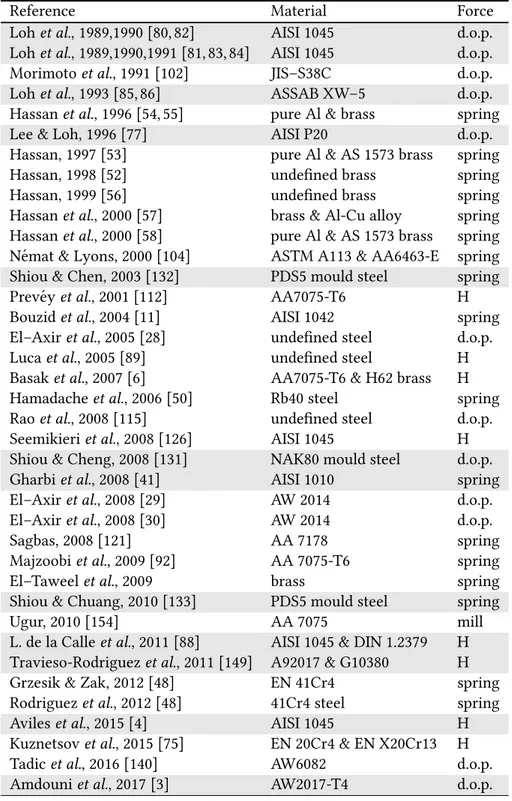
2.1 Ball burnishing references on steel, aluminium and cuprous alloys. Light grey: milling-machine tools. White: lathe tools. . . 21 2.2 Ball burnishing references on stainless steel, titanium and nickel
al-loys. Light grey: milling-machine tools. White: lathe tools. . . 23 3.1 Spring calibration parameters calculated at different compression
ve-locities. . . 48 3.2 Dynamic specifications imposed for the VABB prototype. . . 48 3.3 Properties of hard PZT8 material used for the piezoelectric actuators
in the VABB tool. . . 51 3.4 Measuring conditions tested during the acoustic emission acquisitions. 55 3.5 Fundamental frequency found for each measured signal and its
am-plitude. . . 58 3.6 Conditions measured during the dynamometric tests. . . 59 3.7 Average goodness of fit of 𝐹𝑣sine fits through the Pearson 𝑅2parameter. 63
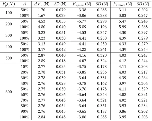
3.8 Average descriptors of sine fits of 𝐹𝑣 and maximum and minimum
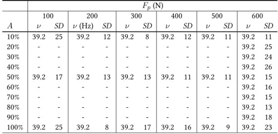
values registered. . . 64 3.9 Average frequency of all sine fits that model the 𝐹𝑣, and standard
de-viation (𝑆𝐷). . . 66 3.10 Mesh size for the image processing of the tool. . . 68 3.11 Absolute and relative pivoting angles of each part of the prototype for
both preload levels. . . 71 4.1 NC codes for every absolute strategy pattern resulting from the
com-bination of the 𝑛𝑝and St. factors. In brackets the Taguchi run in which
they are to be executed. . . 78 4.2 Experimental design derived from a 𝐿27(313) Taguchi orthogonal array. 80
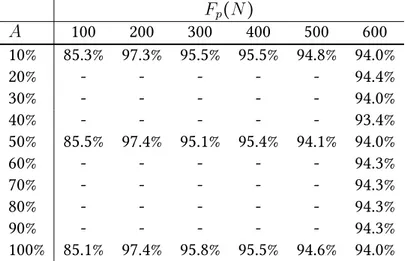
4.3 Factors and levels at the Taguchi array for AISI 1038 and Ti-6Al-4V specimens. . . 82 4.4 Descriptors and factors kept constant in the tests. . . 82 4.5 Calculation of the signal-to-noise ratio in function of the goal of the
experiment. . . 84 4.6 12 S parameter set for surface topography assessment, as defined in
the ISO 25178. . . 87 4.7 Central moments of a surface height distribution. After King & Davis
(1982) [69] . . . 87 4.8 The 13 V parameter set, as defined in the ISO 25178. . . 91 4.9 Errors calculated from the repeatability of S parameters on the
ma-chined surfaces. . . 93 4.10 Retained topological parameters from the S set. . . 94 4.11 Experimental characteristics of X-ray diffraction measurements. . . 102 4.12 AISI 1038 weight composition. . . 102 4.13 AISI 1038 properties, as characterised by Travieso-Rodr´ıguez (2010)
[148]. . . 103 4.14 Hardness measurements performed on the AISI 1038 specimens. . . 104 4.15 Ti-6Al-4V weight composition according to AFNOR L14-601. . . 105 4.16 Grade 23 Ti-6Al-4V properties. . . 105 4.17 Hardness measurements performed on the Ti-6Al-4V specimens. . . 105 4.18 Machining parameters applied to obtain the three original surface
topologies. . . 108 5.1 Summary of retained two- and three-dimensional topological
param-eters. . . 115 5.2 Parameters to apply VABB on AISI 1038 end-milled surfaces, based on
ANOVA mean results. Optimisation target: minimum texture amplitude. 124 5.3 Recommended parameters to ball-burnish AISI 1038 end-milled
sur-faces. Optimisation target: Gaussian surface with minimum texture amplitude. . . 141 5.4 Parameters to apply VABB on Ti-6Al-4V end-milled surfaces, based on
ANOVA mean results. Optimisation target: minimum texture amplitude. 146 5.5 Recommended parameters to ball-burnish Ti-6Al-4V ball-end milled
surfaces. Optimisation target: Gaussian surfaces with minimum tex-ture amplitude. . . 156
LIST OF TABLES
5.6 Main topology descriptors of machined surfaces, including 𝑆0 0 (AISI
1038). . . 156 5.7 60Cr3 chromium steel mechanical properties. . . 163 5.8 Optimal parameters to apply VABB on AISI 1038 surfaces according
to different RS targets, based on ANOVA mean effects. . . 176 5.9 Optimal parameters to ball burnish AISI 1038 surfaces based on real
experimental results . . . 177 5.10 Optimal parameters to ball burnish Ti-6Al-4V surfaces according to
different RS targets, based on ANOVA mean effects. . . 185 5.11 Optimal parameters to ball burnish Ti-6Al-4V surfaces based on real
experimental results . . . 187 5.12 Summary of optimal parameters to ball burnish AISI 1038 surfaces
based on texture and RS criteria. . . 188 5.13 Summary of optimal parameters to ball burnish Ti-6Al-4V surfaces
based on texture and RS criteria. . . 189 5.14 Tested conditions for hardness tests on AISI 1038 𝑆0
1. . . 191
5.15 Tested conditions for hardness tests on Ti-6Al-4V 𝑆0
1. . . 195
A.1 L27(313) Taguchi orthogonal array. After Taguchi et al., 2005 [142] . . 206
A.2 Taguchi array followed for the experimental testing of AISI 1038. . . . 207 A.3 Taguchi array followed for the experimental testing of Ti-6Al-4V. . . . 208 A.4 Actions included in the model and their degrees of freedom. . . 209 A.5 Sisson-Vigier incidence matrix of orthogonality of the experimental
List of Symbols
General parameters
𝐴 Piezoelectric amplitude
𝐴0 Fundamental frequency amplitude . . . 58
𝛥𝐹𝑣 Half-cycle amplitude of the vibratory component . . . 61
𝛥𝑧 Spring compression length . . . 46 𝐸 Young’s module . . . 51 𝑓0 Fundamental frequency transmitted by VABB prototype . . . 58
𝐹0 Spring precompression force . . . 46
𝐹𝑏 Burnishing force . . . 44
𝐹𝑝 Burnishing preload . . . 44
𝐹𝑣 Vibratory component of burnishing force . . . 44
𝜑0 Sine phase of fitted ultrasonic signal . . . 61
ℎ𝑝 Depth of penetration . . . 16
𝜂 Low-frequency burnishing force variation . . . 45 𝑘 Spring elastic constant . . . 48 𝜔 Sine angular frequency of fitted ultrasonic signal . . . 61 𝜌 Density . . . 51 Piezoelectricity
D Electric displacement . . . 50 𝑑𝑖𝑗 Piezoelectric strain constant along 𝑗 due to electric field along 𝑖 . . . 50
𝐼 Intensity . . . 52 𝑞 Number of piezoelectric disks in a stack . . . 51 SE Piezoelectric compliance coefficient matrix . . . .50
𝜎 Piezoelectric stress vector . . . 50 𝑡 Piezoelectric thickness . . . 50 𝑉 Voltage . . . 51
𝜉𝜎 Piezoelectric electric permittivity matrix . . . 50
𝑍 Impedance . . . 52 X-ray diffraction parameters
𝜓 Tilt angle of the collimator with regards to surface . . . 99 𝜑 Position of X-ray collimator goniometer . . . 99 𝜃 Bragg’s reflective angle . . . .99 Texture and roughness parameters
𝜆𝑐 Cut-off length for roughness filtering . . . 115
𝑚𝑚𝑖𝑛 Least slope in AF curves . . . 134
𝑀𝑚𝑖𝑛 𝑀𝑟value of point in least slope point of AF curves . . . 134
𝑀𝑟 AF curve material ratio . . . 91
𝑀𝑟1 Peak material ratio . . . 91
𝑀𝑟2 Valley material ratio . . . 91
𝑅𝑎 Average surface roughness . . . 24
𝑅𝑞 RMS roughness . . . 26
𝑆𝑎 Arithmetical mean surface height . . . 87
𝑆𝑎𝑙 Fastest decay autocorrelation length . . . 87
𝑆𝑑𝑞 RMS gradient . . . 87
𝑆𝑑𝑟 Developed interfacial area ratio . . . 87
𝑆𝑘 Abbot-Firestone core distance . . . 91
𝑆𝑘𝑢 Surface texture kurtosis . . . 87
𝑆𝑚𝑞 Abbot-Firestone relative material ratio . . . .91
𝑆𝑝 Surface maximum peak height . . . 87
𝑆𝑝𝑘 Abbot-Firestone peak height . . . 91
𝑆𝑝𝑞 Abbot-Firestone plateau RMS . . . 91
𝑆𝑞 Surface RMS height . . . 87
Σ𝑠 Area under the AF curve slope function . . . 130
𝑆𝑠𝑘 Surface texture skewness . . . 87
𝑆𝑡𝑑 Surface texture direction . . . 87
𝑆𝑡𝑟 Surface texture aspect ratio . . . 87
𝑆𝑣 Surface maximum valley depth . . . 87
𝑆𝑣𝑘 Abbot-Firestone valley depth . . . 91
𝑆𝑣𝑞 Abbot-Firestone dale RMS . . . 91
𝑆𝑥𝑝 Abbott-Firestone peak extreme height . . . 91
LIST OF TABLES
𝑉𝑚𝑐 Abbott-Firestone core material volume . . . 91
𝑉𝑚𝑝 Abbott-Firestone peak material volume . . . 91
𝑉𝑣𝑐 Abbott-Firestone core void volume . . . 91
𝑉𝑣𝑣 Abbott-Firestone valley void volume . . . 91
Abbreviations
𝐴𝑁 𝑂𝑉 𝐴Analysis of Variance . . . 84 𝐴𝐴𝐶𝐹 Areal autocorrelation function of a surface . . . 89 𝐴𝐹 Abbott-Firestone . . . .90 𝐹 𝐸𝑀 Finite element model . . . 161 𝐹 𝑅𝑈 Force regulation unit . . . 46 𝐹 𝑇 𝑈 Force transmission unit . . . 53 𝑁 𝑉 𝐴𝐵𝐵Non-vibration-assisted ball burnishing . . . 33 𝑃 &𝑉 Peak & valley set . . . 92 𝑅𝑆 Residual stress . . . 98 𝑆𝐷 Standard deviation . . . 64 𝑆⇑𝑁 Signal-to-noise ratio . . . 82 𝑉 𝐴𝐵𝐵 Vibration-assisted ball burnishing . . . 33 𝑉 𝑇 𝑈 Vibrations transmission unit . . . 48
Science is organised knowledge; wis-dom is organised life.
Immanuel Kant
1
Introduction
1.1
Motivations and antecedents
The introduction of new materials has been one of the major historical facilitators for the enhancement of industrial products. For instance, a big leap forward in the aerospace manufacturing industry has been the expansion of composites in crucial components and parts such as the fuselage or major control surfaces. However, metal-lic components shall never be totally replaced, as they provide unique attributes dif-ficult to be substituted by other materials.
Metallic parts are predominantly shaped from raw materials through machining routines. Although chip removal processes are nowadays highly reliable due to the expertise acquired during the last decades, innovation can always be achieved by developing alternative finishing methods to enhance the surface integrity of engi-neering parts. Indeed, today the term enhancement contemplates additional metrics other than adequate dimensioning or accurate material selection. In that respect, tailor-made surface integrity on workpieces is determinant to optimise product per-formance, and maximise the longevity and reliability of engineering parts. For
in-stance, about 56% of catastrophic failure in turbine blades are caused by cracks initi-ated in positively stressed machined surfaces under high-frequency fatigue regimes, and can be prevented with adequate finishing treatments after machining, according to Prev´ey et al. (2002) [113]. In this field, ball burnishing has proved to deliver bet-ter results in bet-terms of surface roughness, residual stress and hardness of objective surfaces, when compared to other processes long integrated in the manufacturing in-dustry such as laser shock peening (Altenberger et al., 2012) [2], electropolishing or shot peening (Shepard et al., 2004) [129]. Thus the necessity to increase the knowledge related to it.
Surface integrity management is remarkably important when special alloys are used to manufacture relevant parts. Advanced materials such as titanium or nickel alloys pose a high difficulty of surface integrity preservation after machining, as note numerous authors such as Ulutan et al. (2011) [155]. Consequently, thorough post-processing techniques are required to rectify the surface integrity. Manufacturing innovation through finishing processes development is not in contradiction with new material application. Much on the contrary, it can contribute to develop a mainstream of manufacturing technology enhancement.
One typical engineering surface that exemplifies the importance of surface in-tegrity control are typically found in the transportation industry, formed by complex forms, conformed by juxtaposed curved surfaces. We can think about turbine blades or landing gears, but also moulds and dies for upsetting operations. This kind of parts are often manufactured through 3 or 5 axis machining with the aid of successive adja-cent passes of hemispherical tools (Figure 1.1). Whereas this ball-end milling strategy allows to achieve complex surfaces by following the desired shape through NC inter-polations generated by a CAM, it also has deep constraints. Guillemot (2010) [49] highlighted the importance of the tilt angle of the hemispherical tool during machin-ing to guarantee a good surface integrity. However, these scientific recommendations are not taken into account by many manufacturers, who often use automatised CAM systems in which hemispherical milling is performed perpendicular to the surface, i.e. with tilt angle equal to zero. That type of machining execution is very often forced by the context defined by the only availability of 3-axis machines with no possibility of adjusting a specific tilt angle for the tool, thus generating a detrimental surface integrity.
In this context, ball burnishing can contribute to improve the described surfaces in industrial parts. The process is known for attaining a comprehensive surface
im-1.1. MOTIVATIONS AND ANTECEDENTS
(a) (b)
Figure 1.1.Hemispherical milling of engineering surfaces. After Fontaine et al., 2006 [38]. a. Overview of a ball-end milled surface. b. Ball-end milling kinematic parameters and scheme of the process.
provement in terms of texture, residual stress and hardness, as well as for being easily manoeuvrable from a procedural point of view. Spring-based ball burnishing tools are easily attachable to NC machines through custom commercial holders, simplify-ing the whole manufactursimplify-ing system and equipment. That means that ball burnishsimplify-ing tools can be used at the same NC machines were previous machining has been per-formed, hence the reduction of handling and processing times, as well as an increase in the automation easiness. Burnishing tools, on the other hand, could be likely to be implemented on advanced automated systems such as robotic arms.
The presented pros attributed to ball burnishing makes it an interesting option to consider as an advanced finishing process for today’s industry. On the other hand, the phenomenon of process assistance is today a highly extended strategy in manufactur-ing engineermanufactur-ing innovation systems [14], since it allows to obtain emergent advan-tages from operations that are already totally integrated in manufacturing workshops. Taking this fact into account, it is worth questioning whether the ball burnishing op-eration can be enhanced by vibration-assistance, in search of emergent effects on industrial materials. In this thesis, the incorporation of ultrasonic vibrations is pro-posed to improve the ball burnishing process. The evidence that this combination can lead to interesting results is based on the physical phenomenon of acoustoplasticity, that is, the reduction of the quastatic stress required to deform a material by the si-multaneous propagation of waves inside it, while causing a residual hardening effect. Isolated results performed by other researchers have lead to think that this
combina-tion can be positive, as shall be presented in the state-of-the-art chapter [13]. As no comprehensive and consistent research has been developed previously, the following subsection presents the contributions expected to be delivered by this dissertation.
1.2
Research contributions
In this dissertation, a new finishing process resulting from modifying the ball bur-nishing process is executed on ball-end milled flat surfaces. At sight of the previously described surfaces, applying experimental design on flat surfaces means that we are dealing with surface states that are not necessarily realistic. However, they are ob-tained through a mastered machining strategy that allows to excerpt control on the surface topology by varying the peaks and amplitudes of the surface texture. On the other hand, they can be considered as preliminary results that shall eventually serve to characterise the process on curved more realistic surfaces.
The modification of the ball burnishing process is to be carried out by overlap-ping an oscillating force on the static burnishing preload, which allows to transmit an ultrasonic wave inside the material that makes it easier to deform plastically. The combination of ball burnishing with the acoustoplastic effect referred in this disser-tation as vibration-assisted ball burnishing (VABB), in contrast to the non-vibration assisted process (NVABB), that is, conventional ball burnishing. The physical basis of the process enhancement is the acoustoplastic or Blaha effect [7]. This effect shows that acoustic and ultrasonic waves propagated inside a material while it is being de-formed, reduce the quasi-static stress required to achieve a certain level of strain. This sort of metal softening has a transient effect, as is only present during the transmis-sion of the wave inside the metal. In other words, when that irradiation stops, most materials show a residual hardening effect. As a process based on plastic deformation, ball burnishing is expected to be a recipient of enhancement through acoustoplastic-ity, which leads to enunciate the main hypothesis posed for this thesis:
The application of acoustoplasticity to enhance the ball burnishing operation leads to a technically feasible technology enabling the successful enhancement of the surface integrity of milled surfaces from topological, mechanical and metallurgical points of view.
1.3. THIS DISSERTATION IN BRIEF
that are due to be answered by a set of well-settled and properly formulated questions, as follows:
1. To what extent can the surface integrity of ball-end milled surfaces be enhanced by the introduction of the acoustoplastic effect in the ball burnishing operation? 2. Is surface texture essentially modified by the vibration-assisted ball burnishing process? Are 𝑅𝑎and 𝑅𝑡, as the classical surface roughness parameters, enough
to describe that change?
3. What are the effects of the vibration-assisted ball burnishing process on the sur-face and sub-sursur-face layers of the material from a mechanical and metallurgical perspective?
4. What is the impact of the original surface state on the results?
At sight of the described scientific issues, and due to the lack of comprehensive results of the VABB process on surface integrity, this dissertation adopts fundamen-tally an experimental scope that shall allow to provide comprehensive data about its results.
Furthermore, to fulfil the objectives of this dissertation, some technical issues can also be identified, and must be tackled to succeed in assessing the effects of the VABB process, and compare it to the non-vibration-assisted one. These technical issues can be described as follows:
1. No VABB tool is currently commercially available. For that reason, an innova-tive ultrasonic VABB prototype must be designed, protected by a patent, man-ufactured and characterised.
2. During the characterisation process, special instrumentation systems shall be required to sample and reconstruct the ultrasonic signals implicated in the pro-cess.
1.3
This dissertation in brief
The reader shall find in this text an extensive analysis of bibliographical studies and theoretical approaches that justify the application of VABB, along with extensive
ex-perimental results obtained from the application of the process on steel and titanium surfaces. The chapters of which it is composed are structured as follows.
Chapter 2 presents a review of bibliographical references that tackle with the issues at stake in this dissertation. Three main parts can be differentiated. The first one presents a definition of the ball burnishing process and different tooling configu-rations. Secondly, the effects of the ball burnishing process on the surface integrity of different materials is presented. The third section of this chapter focuses on explaining acoustoplasticity mechanisms as proposed by some authors, and the few references dealing with it to assist the ball burnishing process.
As no VABB prototype is available commercially, it must be designed, charac-terised and tested. Chapter 3 shows all activities undertaken to this aim. Piezoelec-tricity is presented as the driver of vibration transmission on which the functioning of the prototype is based. A mechanical construction composed of three units is pro-posed in this chapter, and materialised in a prototype which is tested by applying acoustic emission, dynamometric measurements and motion track. These techniques ultimately deliver the characteristics of the vibratory force transmitted by the piezo-electric module installed inside the tool casing.
The prototype is then tested on Ti-6Al-4V and AISI 1038 surfaces. These materials have been chosen due to their industrial interest for applications on workpieces ex-pected to function in highly demanding environments, such as fatigue regimes, thus requiring thorough finishing surface states. Specifically, the first one is known for its generalised presence in various aeronautical workpieces, whereas the AISI founds extended applications in gears, axes or power shovels. With that aim, an experimen-tal design based on Taguchi orthogonal arrays is proposed, as explained in Chapter 4. That chapter also includes the set of techniques which are deployed to evaluate the surface integrity results on both materials. Specially interesting is the proposal of texture measurement through a comprehensive set of three-dimensional parameters, which has no precedents in the analysis of ball burnishing results.
Finally, the experimental results are compiled and explained in chapter 5. First, topological results are shown for both materials. The incorporation of surface param-eters, in contrast to the two-dimensional parameters traditionally used to characterise burnished surface, is introduced. Then, the residual stress generated on the different VABB and NVABB patches is analysed. Finally, mechanical parameters describing the surface are presented to fulfil a comprehensive surface integrity characterisation of
1.3. THIS DISSERTATION IN BRIEF
the VABB effects, including both metallography analysis and deep hardness measure-ment.
The knowledge developed along the referred chapters leads to formulate final con-clusions and expected future works at the end of the text, which also includes appen-dices with relevant data not included in the report.
2
State of the art
This chapter includes the results emerging from an extensive bibliographical research which tackles with different burnishing references. Burnishing itself is a generic pro-cess that comprises innumerable versions defined by the contextual conditions that govern its execution, such as the geometry and construction of the burnishing tool. The first section of this chapter is a descriptive one, exposing the different burnishing versions by analysing different burnishing tools and the parameters governing the operation. The second section in this chapter establishes a definition of surface in-tegrity, and includes the results found by ball burnishing on different materials. The first descriptive references found for the process were published in the 80’s, and focus on steel, aluminium and copper alloys. The following years brought a breakthrough of the burnishing knowledge through the exploration of further similar alloys, and the incorporation of stainless steel to the system. Still today, the lack of results on the burnishing operation performed on titanium alloys or superalloys leaves a vast exploration territory for new research.
The VABB operation is defined and introduced in next section. The Blaha effect, which justifies its effectiveness, also known as acoustoplasticity, is presented along with a historical review of different explanations proposed by different authors. Last
of all, the scarce references found related to the VABB process are presented.
2.1
General aspects of the burnishing operation
Burnishing is a general term that referes to a surface finishing operation based on local plastic deformation attained through the action of an indenter with a cylindrical or spherical geometry, which rolls over the objective surface while transmitting a preload [103]. Plastic deformation during the feed motion is successfully performed as a result of frictional engagement of the indenter and the surface irregularities.
The process is performed along successive adjacent passes with the aim of cov-ering the whole target surface, as shown schematically in Figure 2.1. During the movement of the tool, the indenter makes contact with the peaks of the texture irreg-ularities. At first, the peak material is deformed elastically, but the extended contact and deformation leads to the final plastification of the material, and its residual strain that is translated into a holistic modification of the surface. Indeed, this process modi-fies the surface integrity of the workpiece, as effects on surface topography, hardness, and residual stresses of subsurface layers are significant [64].
Figure 2.1.Schematic representation of the ball burnishing process.
Conceptually, the plastification process is gradual. The instantaneous contact area between the indenter and the surface can be described as a tear-shaped region, cov-ering the wide range of strain states, starting from the elastic deformation in the en-gagement zone, until the superfinishing zone at the points with longer contact with the indenter. This mechanism provides the general roughness improvement along the burnishing direction [79]. Surface roughness is a fundamental feature of the
sur-2.1. GENERAL ASPECTS OF THE BURNISHING OPERATION
face integrity of the part, not solely for outer aspect matters, but also for its general performance. Poor surface finish disables geometric tolerances, and it affects wear resistance, fatigue life, and load-carrying capacity.
On the other hand, as the instantaneous application of the burnishing force is local, the topological changes are hardly larger than 10 µm, so that general geometry of the part is not changed. Therefore, form errors and the general shape of the part are not significantly rectified through burnishing. This makes the process suitable for the finishing of parts manufactured until their final dimensions, and is especially interesting in manufacturing contexts where high precision results are required. It is the case, for instance, of mould manufacturing, filleted bearing components, or curved surfaces.
Burnishing can be found in the bibliography after diverse designations. Practi-cally, the main difference among the different processes based on different tools is the objective that justifies the execution of the process. Deep Rolling (DR) is used to refer to the execution of ball or roller burnishing with the aim of inducing high compressive residual stresses and increasing cold work on the part surface. When the sought objective is decreasing the surface roughness of the objective part, the process is generally denoted as Low Plasticity Burnishing (LPB) [2].
From a systemic point of view, burnishing can be defined as a set of interrelated resources, whose function is to perform the finishing of an objective workpiece, and whose combination define a singular burnishing system. Under this perspective, Fig-ure 2.2 shows a fishbone diagram of the different aspects which define burnishing systems. Items belonging to the tooling system categories allow to establish a certain classification of different burnishing operations. That is, by varying the shape of the indenter, the force regulation method, or the mechanical composition of a tool to be attached to different machines, diverse burnishing operations are feasible.
Burnishing tooling is therefore highly important when the implementation of a specific burnishing operation must be carried out. It plays a fundamental role in the definition of the burnishing system, as it enables the application of the process on one or several specific machines, and allows to regulate and control most of the burnishing parameters governing the process, and that determine the burnishing results. The next subsections present different burnishing tooling configurations, as a first step to decide the general features of the design of the VABB tool.
Figure 2.2.Items and descriptors comprising the burnishing manufacturing system.
2.1.1
An overview of burnishing tooling
The scientific bibliography shows a great variety of burnishing tool designs. In gen-eral, a burnishing tool must be conceived to fulfil the following requirements:
• It must be attachable to a specific machine tool where the process must be de-veloped.
• It must guarantee mechanical engagement between the indenter and the mate-rial, allowing the free movement of the former while maintaining its mechanical integrity.
• It must bring into play the whole of the desired burnishing parameters, espe-cially preload, while ensuring accessibility to the target surface.
Basic tools utilised originally in general applications of the burnishing technique were applied on simple geometries such as bores and shafts, hydraulic cylinders, pis-tons for hydraulic systems, or fillets. Classical burnishing tool–workpiece configu-rations can be consulted at Figure 2.3. The lack of automation and handling limi-tations presented by conventional machines made difficult to finish more complex parts. Later, the generalisation of NC machines in manufacturing workshops, and the emergence of more simple fixation systems, enabled new designs. The technique was subsequently embraced for more complex geometries such as the finishing of free-form parts (e.g. moulds), and contributed to its expansion [77, 132].
2.1. GENERAL ASPECTS OF THE BURNISHING OPERATION
Figure 2.3. Classical burnishing tool configurations on lathe and milling machines. After Murthy, 1981 [103]
tool. Roller tools have been classically more widespread, for its higher simplicity in terms of preparatory activities and force adjustment [32, 33, 90, 92]. Regarding the roller geometry, dimensions and profiles are also diverse. Rollers with higher cylindrical land would allow the execution of the process by selecting higher feeds, as the contact surface between the tool and the part is higher. However, rollers lack of the versatility that balls offer to burnish, since they are inefficient to treat complex surfaces, extensively found in the advanced manufacturing industry.
However, roller burnishing tools are also known for their lower effectiveness in hardness improvement, and require higher forces to obtain the same improvements as with sphere shape indenters. Consequently, ball burnishing can be presented as a
more advantageous process in terms of absolute results. Comparative research has proved that ball burnishing is able to achieve significantly lower surface roughness and higher hardness with lower forces in materials such as AISI 1335 steel [50], and non-ferrous alloys [53]. For that reason, the tool that shall be designed in this disser-tation shall be based on a ball-burnishing configuration.
2.1.1.1 Special burnishing tool configurations
The development of tools with specific configurations is one of the innovative ap-proaches to burnishing development (Figure 2.4). Multi-roller tools can be found at several bibliographical references. Thamizhmanii et al. (2009) [145] tested a frontal multiroller tool on TA6V speciments, and Tadic et al. (2013) [141] designed and suc-cessfully tested a multiroller tool on aluminium parts. Multi-ball tools can also be found at Gharbi et al. (2010) [41] and Tadic et al. (2016) [140]. In general, multi-indenter tools show a remarkable stability of the process due to higher surface con-tact of the burnishing indenters and the workpiece, although the range of objective geometries is not so wide.
More complex configurations have been also conceived and prototyped. El–Axir & Ibrahim (2005) [28] designed and mounted a multi-ball tool embedded in a centre rest, being able to burnish on a lathe through a steadier regime, and showing better results in terms on final roundness, compared to conventional burnishing. Okada et al. (2015) [107] designed a roller tool able to adapt at will the burnishing angle, and after testing it on ASTM 2017 aluminium and ASTM 1055 carbon steel specimens, concluded that burnishing at a 45 degrees angle is the optimum process in terms of surface roughness. Integrating cutting tools and finishing burnishing tools on one single piece has also been explored by Segawa et al. [127].
2.1.2
General description of ball burnishing parameters
In manufacturing engineering, controlling the parameters of any process is necessary to comply with design specifications, guarantee the repeatability of results, and their reproducibility from a small-scale research context to a real manufacturing workshop. Burnishing is no exception, as proves the preponderance of bibliographical references which focus on testing different levels of burnishing parameters on a great variety of objective materials. This subsection explains the different parameters that govern the
2.1. GENERAL ASPECTS OF THE BURNISHING OPERATION
(a) (b) (c)
(d) (e) (f)
Figure 2.4. Special burnishing tool configurations. a. Milling & burnishing tool [127] b. Center rest multi-ball tool [28] c. Multi-roller tool [141] d. Multi-ball tool [41] e. Adjustable roller tool [107] f. Multi–ball tool [140]
operation.
2.1.2.1 Plastic strain parameters: burnishing force and number of passes The most influential parameter on ball burnishing results is the burnishing force, that is, the normal force transmitted by the burnishing tool to the workpiece surface in order to deform plastically its microtopology. The specific pressure applied on the workpiece to achieve that plastic deformation is the direct result of this force, and must exceed the yield point of the material to succeed in achieving good results. It can be therefore considered as the essential physical driver of plastic strain.
The constructive configuration of the burnishing tool defines the way through which the force is controlled and transmitted to the workpiece. In other words, ac-cording to the technical solution adopted to apply the force on the surface through the ball on the surface, the force is controlled differently. From this point of view, mainly
three kind of tool can be distinguished, as can be observed in Figure 2.5. These three solutions are explained below.
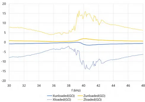
(a) (b) (c)
Figure 2.5. Force regulation systems in classical burnishing tools. a. Depth-of-penetration tool [80]. b. Hydrostatic tool [119]. c. Spring-regulated tool [52]
Depth of penetration This solution appears to be the original force regulation method, as is found in all the oldest references (Figure 2.5.a). The tools based on this force transmission principle are ended by a spherical shape in which the ball is housed, allowing its free rolling. In order to regulate the force, the tool tip is pressed onto the target surface. The force is exerted by screwing the supporting rod in which the burnishing ball is embedded. The linear length along which the screw is tightened along the supporting rod is called depth of penetration ℎ𝑝 . The burnishing force or
preload, 𝐹𝑝, derived from this mechanism can be therefore deduced from the
approx-imate solution of slipping of a rigid sphere over a plastic semi-plane, as shown in Eq. 2.1 [103].
𝐹𝑝 =
𝜋
4 ℎ𝑝𝐻𝑉 𝑅 (2.1)
where 𝐻𝑉 is the Vickers hardness of the material,and 𝑅 is the indenter radius. The fact that the preload is calculated through this indirect method does not allow its accurate regulation. Therefore, the actual values of the burnishing force applied during the burnishing process can only be known if the machine is equipped with a force measuring device. Consequently, this solution is advisable to burnish compli-cated geometries, which do not allow the application of other pressing systems [29]. Hydrostatic pressure These kind of tools often use a ceramic or chrome-steel ball embedded inside a support piece at the tip, which is connected to an inner channel
![Figure 2.5. Force regulation systems in classical burnishing tools. a. Depth-of-penetration tool [80]](https://thumb-eu.123doks.com/thumbv2/123doknet/2133800.8670/50.892.121.737.264.448/figure-force-regulation-systems-classical-burnishing-depth-penetration.webp)