UNIVERSITÉ DE MONTRÉAL
MULTIFUNCTION TRANSCEIVER ARCHITECTURE AND TECHNOLOGY FOR FUTURE WIRELESS SYSTEMS
JABER MOGHADDASI
DÉPARTEMENT DE GÉNIE ÉLECTRIQUE ÉCOLE POLYTECHNIQUE DE MONTRÉAL
THÈSE PRÉSENTÉE EN VUE DE L’OBTENTION DU DIPLÔME DE PHILOSOPIAE DOCTOR
(GÉNIE ÉLECTRIQUE) AOÛT 2017
UNIVERSITÉ DE MONTRÉAL
ÉCOLE POLYTECHNIQUE DE MONTRÉAL
Cette thèse intitulée :
MULTIFUNCTION TRANSCEIVER ARCHITECTURE AND TECHNOLOGY FOR FUTURE WIRELESS SYSTEMS
présentée par : MOGHADDASI JABER
en vue de l’obtention du diplôme de : Philosophiae Doctor a été dûment acceptée par le jury d’examen constitué de :
M. CARDINAL Christian, Ph. D., président
M. WU Ke, Ph. D., membre et directeur de recherche M. AKYEL Cevdet, D. Sc. A., membre
DEDICATION
To my Love, Hanieh
ACKNOWLEDGEMENTS
First and foremost, I would like to express my deepest gratitude to Dr. Ke Wu who has given me the chance to join his team in the PolyGrames Research Center and study under his supervision. Prof. Wu trusted me since the first day of studies and allowed me to meet the challenge of studying directly for the highest graduate level without going through the regular procedure. He also freely agreed on a thesis subject on which I felt passionate to work. Even though I have had his insightful guidance on the main research path I have always been given enough freedom to make mistakes and learn from them and more importantly to dare to try creative paths. Throughout the time of studying, Prof. Wu has encouraged me for many opportunities including research grant applications and student competitions that helped me to build up a bright background. I would appreciate his kind supports for ever not only because of these reasons but also for his soothing smiles and inspiring speeches during my hardest days of research.
My sincere thanks go to the jury members for their time and reading my thesis and providing me with very helpful comments.
I am also very grateful to the team of technicians at the PolyGrames Research Center, i.e., Jules Gauthier, Steve Dubé, Maxime Thibault, and Traian Antonescu who helped me within all in-lab circuit fabrication and measurement processes. My gratitude extends to Mr. Jean-Sébastien Décarie and Mrs. Rachel Lortie who gave me hand in solving the IT problems and completing the administrative tasks.
I also would like to thank my love, Hanieh who has stayed by my side during the whole study. Hanieh has always had her extraordinary love and kindness for me which encouraged me to pursuit toward the complete achievements. She felt the fatigue and bores of my hard days but made her efforts to keep me motivated and have eyes open for delightful future days. I am very much indebted to her for accompanying me faithfully during these years of study. Moreover, I appreciate the kind support of my family since I was a child.
I have also had great chances to have the cooperation with our, at the time, post-doctorate fellows. I want to thank Dr. Lin Li, Dr. Tarek Djerafi, Dr. Anthony Ghiotto, and Dr. Liang Han. Furthermore, I appreciate the nice friendship of my friends at the Polytechnique Montreal, including Yangping Zhao, Kuangda Wang, Ali Doghri, Jiapin Guo, Faezeh Fesharaki, Carlos Lorenz and Sulav Adhikari.
RÉSUMÉ
Depuis la toute première transmission sans fil, les ondes radiofréquences ont été progressivement mises en valeur et exploitées dans un nombre de plus en plus important d'applications. Parmi toutes ces applications, la détection et la télécommunication sont sans doute les plus indispensables de nos jours.
Il existe un grand nombre d’utilisations des radiofréquences, incluant les transports intelligents pour lesquels les véhicules doivent être équipés à la fois de radars et de dispositifs de communication afin d’être capables de détecter l'environnement ainsi que de réaliser la communication avec d'autres unités embarquées. La technologie émergente 5G est un autre exemple pour lequel plusieurs capteurs et radios devraient être capables de coopérer de manière autonome ou semi-autonome. Les principes de fonctionnement des systèmes radars et radio sont toutefois différents. Ces différences fondamentales peuvent entraîner l'utilisation de différentes architectures de traitement du signal et d'émetteur-récepteur, ce qui peut poser des problèmes pour l'intégration de toutes les fonctions requises au sein d'une seule et même plate-forme.
En dehors de cela, certaines applications requièrent plusieurs fonctions simultanément dans un même dispositif. Par exemple, les systèmes de détection d'angle d'arrivée 2D nécessitent d'estimer l'angle d'arrivée (AOA) du faisceau entrant dans les plans horizontal et vertical simultanément. La communication radio multi-bandes et multi-modes est un autre exemple pour lequel un système radio doit être capable de communiquer dans plusieurs bandes de fréquences et dans plusieurs modes, par exemple, un duplexage en fonction de la fréquence ou du temps.
À première vue, on peut penser que l'assemblage de plusieurs dispositifs distincts n'est pas la meilleure solution en ce qui concerne le coût, la simplicité et la fonctionnalité. Par conséquent, une direction de recherche consiste à proposer une architecture d'émetteur-récepteur unifiée et compacte plutôt qu’une plate-forme assemblant de multiples dispositifs distincts. C’est cette problématique qui est spécifiquement abordée dans ce travail.
Selon les fonctions à intégrer dans un seul et unique système multifonctionnel, la solution peut traiter plusieurs aspects simultanément. Par exemple, toute solution réalisant l'intégration de fonctions liées au radar et à la radio devrait traiter deux aspects principaux, à savoir : la forme d'onde opérationnelle et l'architecture frontale RF. Cependant, dans certains autres exemples mentionnés ci-dessus, tels que le système de détection DOA 2D, une forme d'onde opérationnelle
identique peut être utilisée et le principal défi de l'intégration de fonctions concernerait l'unification des multiples émetteurs-récepteurs essentiels dans une seule unité. Par conséquent, différentes stratégies d'intégration de systèmes multiples devraient être envisagées pour ces deux catégories. Dans ce travail, les deux catégories sont étudiées et différentes solutions sont présentées.
Dans la première catégorie, les systèmes de communication radar commune (RadCom) sont développés pour des fonctionnalités plus robustes et une mise en œuvre compacte et unifiée. En outre, le schéma d'intégration du domaine en temps qui s'est révélé performant en termes de simplicité, de coût et d'efficacité par rapport à ses homologues en fréquence ou en domaine de code, a été étudié pour d'autres améliorations. Dans un premier temps, la fonction de détection d'angle a été ajoutée au schéma d'émetteur-récepteur présenté au début en améliorant l'architecture du récepteur. Un émetteur-récepteur multifonctionnel reconfigurable pour de futurs services intégrés de fusion de données de détection radar et de radiocommunication (RadCom) est étudié et développé dans ce travail. Cette alternative proposant des architectures à la pointe de la technologie présente une intégration sans précédent de toutes les fonctions de détection radar et de communication radio dans une plate-forme de division temporelle. En outre, il est capable d'offrir une fonction de positionnement à la fois des objets mobiles et statiques avec une résolution améliorée, en plus de fournir une capacité de communication de données. Les incompatibilités de conception et de performance entre les systèmes radar et radio sont explorés et étudiés. Une approche systématique de haut en bas est également présentée. Elle comprend une méthodologie étape par étape, des considérations de conception de blocs de construction et la simulation au niveau système. Dans le but de valider le schéma proposé, un prototype basse fréquence a été développé et sa performance est évaluée. Grâce à diverses mesures au niveau du système, le schéma proposé a démontré des caractéristiques intéressantes en liaison avec les fonctions radar et radio. Avec le mode radar, la capacité ajoutée de la détection d'angle et la résolution améliorée de portée par rapport à la version précédemment démontrée rend le système approprié pour des applications d'assistance. Dans le mode radio, le démonstrateur du système s'est avéré d’une bonne capacité de communication avec un débit de données de 25 Mbps.
Par la suite, ce travail s’est consacré au développement de nouvelles architectures d'émetteurs-récepteurs pouvant unifier plusieurs émetteurs-d'émetteurs-récepteurs avec des architectures et / ou spécifications essentiellement différentes. Dans cette partie, l’objectif a été la réduction des tailles et des coûts des systèmes d'émetteurs-récepteurs multifonctionnels. En raison des caractéristiques
intéressantes des architectures interférométriques, elles ont été choisies. Les architectures multiports souffrent d'une sensibilité relativement faible et d'une plage dynamique limitée, mais elles sont supérieures en termes de bande passante facilement réalisable, de coût, de simplicité, de consommation d'énergie extrêmement faible, de reconfigurabilité et de pluralité de ports disponibles. En effet, ces caractéristiques font des architectures multiports, des architectures prometteuses pour les futurs systèmes intégrés, notamment autour des bandes de fréquences millimétriques.
La technique de l'interféromètre à six ports a déjà été utilisée dans les systèmes sans fil pour diverses applications, y compris la démodulation / modulation en quadrature, la détection de petits mouvements d'objet ou même l'estimation de l'AOA du faisceau entrant. Néanmoins, à notre connaissance, un unique émetteur-récepteur multiport, capable de gérer plusieurs de ces fonctions simultanément, n'a jamais été proposé.
Dans ce travail, de nouveaux réseaux multiports avec conditionnement de phase spécifique sont développés. Ils intègrent la plupart des fonctions de systèmes six-ports précédemment rapportées. Les architectures proposées à multiports sont examinées autour de 5,8 GHz puis développées et mises en œuvre pour une exploitation autour de 77 GHz. L'intégration dans ce dernier schéma est obtenue principalement par une nouvelle configuration des signaux aux ports d'entrée, un nouveau traitement de phase des signaux d'entrée dans un réseau passif à huit ports et également un post-traitement complémentaire des signaux de sortie. Il peut être utilisé à des fins de localisation, c'est-à-dire de détection de portée et d'angle, ou de communication.
Dans la deuxième catégorie de systèmes multifonctionnels, une technique interférométrique multiport est développée pour un système de détection DOA 2D. Ce système se compose de trois parties principales, à savoir, l'antenne, le récepteur interférométrique à ondes multiples ou le discriminateur de phase et le processeur de signal. Dans ce schéma, la capacité des estimations simultanées 2D AoA est rendue possible grâce à une combinaison de configuration d'antenne spécifique et récepteur interférométrique multiport pour la discrimination de phase. L'antenne est composée de quatre éléments récepteurs situés dans le même plan, et agencé dans configuration en forme de losange. Les signaux reçus manifestent des différences de phase relatives qui contiennent des informations sur la direction d'arrivée du faisceau. Avec la topologie de jonction à huit ports proposée, l'interféromètre extrait ces différences de phase informative et les fournit à un algorithme
de traitement de signal simple permettant l’estimation des deux angles. L'analyse théorique du schéma de détection du DOA proposé est présentée ainsi que des résultats de simulation au niveau du système, afin de faire la preuve de concept. En outre, une technique d'étalonnage appropriée est formulée afin de traiter les non-idéalités et les erreurs consécutives dans la pratique. Également, la mise en œuvre du système présenté est brièvement discutée dans cette thèse pour son prototypage à plus de 60 GHz. Enfin, la performance du système prototypé est évaluée à l'aide d'un ensemble de mesures au niveau du système. D'excellents résultats sont obtenus, validant ainsi la fonctionnalité exceptionnelle du système proposé.
Dans une autre application de la deuxième catégorie, de nouvelles architectures d'émetteurs-récepteurs multi-ports sont présentées pour des applications en radios à double bande et à double mode. Dans ce travail, le concept présenté est soutenu par des simulations et des analyses au niveau du système.
De plus, plusieurs composants passifs sont présentés dans ce travail. Une structure balun à large bande est développée grâce à une combinaison hybride de guidage d'ondes intégrées au substrat (SIW) et de topologies de lignes de dérivation antipodales. La différence de phase de 180 ° est obtenue par la rotation de la polarisation du champ E à travers les sections de la ligne des ailettes antipodales dans deux branches non équilibrées. En raison de l'indépendance de ce déphasage par rapport à la constante de propagation et à la longueur d'onde, on obtient une différence de phase constante de 180° sur une large plage de fréquence. Le balun proposé est prototypé et démontré pour fonctionner à des fréquences d'ondes millimétriques de 70 GHz à 90 GHz. Les résultats de mesure montrent d’excellentes performances avec une perte d'insertion très faible et une différence de phase de 180 ° entre les ports déséquilibrés dans une large bande de fréquence.
De surcroit, une topologie simple de coupleur hybride 180° avec des entrées et des sorties non intercalées est développée dans ce travail. Cette topologie de coupleur hybride avec entrées disponibles d'un côté et sorties du côté opposé simplifient l'acheminement des signaux lorsqu'ils doivent être utilisés dans des circuits intégrés avec d'autres composants. La topologie proposée du coupleur est théoriquement analysée. Le coupleur a été démontré à 77 GHz et évalué en mesure sur wafer. Le bon accord obtenu entre les résultats de mesure et de simulations montre la fiabilité des performances du coupleur hybride 180° proposé.
ABSTRACT
Since the very early wireless transmission of radiofrequency signals, it has been gradually flourished and exploited in a wider and wider range of applications. Among all those applications of radio technology, sensing and communicating are undoubtedly the most indispensable ones. There are a large number of practical scenarios such as intelligent transportations in which vehicles must be equipped with both radar and communication devices to be capable of both sensing the environment and communication with other onboard units. The emerging 5G technology can be another important example in which multiple sensors and radios should be capable of cooperating with each other in an autonomous or semi-autonomous manner. The operation principles of these radar and radio devices are different. Such fundamental differences can result in using different operational signal, distinct signal processing, and transceiver architectures in these systems that can raise challenges for integration of all required functions within a single platform.
Other than that, there exist some applications where several functions of a single device (i.e. sensor or radio) are required to be executed simultaneously. For example, 2D angle-of-arrival detection systems require estimating the angle of arrival (AOA) of the incoming beam in both horizontal and vertical planes at the same time. Multiband and multimode radio communication is another example of this kind where a radio system is desired to be capable of communication within several frequency bands and in several modes, e.g., time or frequency division duplexing.
At a first glance, one can feel that the mechanical assembling of several distinct devices is not the best solution regarding the cost, simplicity and functionality or operability. Hence, the research attempt in developing a rather unified and compact transceiver architecture as opposed to a classical platform with assembled multiple individual devices comes out of horizon, which is addressed specifically in this work.
Depending on the wireless functions that are to be integrated within a single multifunction system, the solution should address multiple aspects simultaneously. For instance, any solution for integrating radar and radio related functions should be able to deal with two principal aspects, namely operational waveform and RF front-end architecture. However, in some other above- mentioned examples such as 2D DOA detection system, identical operational waveform may be used and the main challenge of functional integration would pertain to a unification of multiple mono-functional transceivers. Therefore, different strategies for the integration of multiple systems
should be considered for these two categories. In this work, both categories are studied and different solutions are put forward.
In the first category, joint radar-communication (RadCom) schemes are developed for more robust functionality and rather compact and unified implementation. Furthermore, the time-domain integration scheme that has been proved to outperform in terms of simplicity, cost and efficiency compared to those counterparts in either frequency or code domain, is studied for further improvements. At the first step, the function of angle detection was added to the early presented transceiver scheme by improving the receiver architecture. A reconfigurable multifunctional transceiver for future integrated data-fusion services of radar sensing and radio communication (RadCom) is investigated and developed in this work. This proposed alternative of the state-of-the-art architectures presents an unprecedented integration of all radar sensing and radio communication functions together in a time-agile scheme. Furthermore, it is capable of offering a positioning function of both moving and static objects with an enhanced ranging resolution in addition to providing the capability of data communication. The design and performance incompatibilities between radar and radio systems are explored and investigated herein. A systematic top-bottom approach is also presented, which involves step-by-step methodology, building block design considerations, and system level simulation. With the purpose of validating the proposed scheme, a low-frequency prototype is developed and its performance is evaluated. Through various system-level measurements, the proposed scheme has demonstrated attractive features in connection with both radar and radio functions. With the radar mode, the added ability of angle detection and the improved range resolution against the previously demonstrated version makes the system suitable for driving assistance applications. With the radio mode, the system demonstrator has proved a great capability of communication at a data rate of 25 Mbps.
Thereafter, the main attention in this work is drawn into developing new transceiver architectures that can unify multiple transceivers with different functions and/or system specifications. This research path is taken in this work with the purpose of reducing size, cost and complexity in the development of multifunctional transceiver schemes. Due to interesting features of the multiport interferometric based architectures, it is selected against conventional architectures for further development. Generally, the multiport architectures suffer from relatively poor sensitivity and limited dynamic range, but they outweigh in terms of easily achievable bandwidth, cost, simplicity, extremely low power consumption, re-configurability and plurality of available
ports. Indeed, these features have inspired the capability of multiport techniques as a promising architecture for future integrated wireless systems especially around millimeter-wave frequency bands.
The six-port interferometer technique has already been used in wireless systems for a variety of applications, including quadrature demodulation/modulation, small object movement detection or even estimation of the incoming beam’s AOA. Nevertheless, a single multiport-based transceiver has not been reported that can handle a multitude of these functions simultaneously, in our best knowledge. In this work, a new multiport network with specific phase conditioning is introduced which integrates most of the previously reported six-port based system functions. The proposed multiport based architecture is examined first around 5.8 GHz and then further developed and implemented for millimeter-wave operation around 77 GHz. The integration within the latter scheme is mostly obtained through a new configuration of connection of input signals at the input ports, a novel phase processing of input signals in an eight-port passive network and also complementary post-processing of output signals. It can be used for AOA sensing as well as data communication. The proposed multiport receiver is modeled and implemented in a transceiver for further evaluation. The excellent functionality of the proposed eight-port receiver is proved through satisfactory system-level measurements in our laboratories.
In the second category of multifunctional systems, multiport interferometric technique is developed for a 2D DOA detection system. This system consists of three main parts, namely antenna, multiport wave interferometric receiver or phase discriminator, and signal processor. In this scheme, the capability of simultaneous 2D AOA estimations is made possible thanks to a combination of specific antenna configuration and multiport interferometric receiver for phase discrimination. The antenna is composed of four receiving elements located in the same plane, which is arranged as a diamond-shaped configuration. The received signals manifest relative phase differences that contain information about the beam’s direction of arrival. With the proposed eight-port junction topology, the interferometer extracts these informative phase differences and leaves them for a simple signal processing algorithm to estimate the two angles. Theoretical analysis of the proposed DOA detection scheme is presented along with system level simulation results for the proof of concept. In addition, an appropriate calibration technique is formulated to deal with non-idealities and consecutive errors in practice. Also, implementation of the presented system scheme is briefly discussed in this thesis for its prototyping over 60 GHz range. Finally, the performance
of the prototyped system is assessed through a set of system level measurements. Excellent results are obtained, thus validating the outstanding functionality of the proposed system.
In another application of the second category, new multiport-based transceiver architectures are presented for applications in dual-band and dual-mode radios. In this work, the presented concept is supported with system level simulations and analysis.
In addition, several passive components, which are in support of our proposed system architecture developments, are presented in this work. A broadband balun structure is developed through a hybrid combination of substrate integrated waveguide (SIW) and antipodal fin-line topologies. The 180o phase difference is made by the rotation of E-field polarization through the antipodal fin-line sections in two unbalanced branches. Due to the independency of this phase shifting with respect to propagation constant and wavelength, a constant 180o phase difference is achieved over a wide range of frequency. The proposed balun is prototyped and demonstrated for operation at millimeter-wave frequencies from 70 GHz to 90 GHz. The measurement results show an excellent performance with very low insertion loss and 180o phase difference between the unbalanced ports in a broad frequency band of interest.
Moreover, a simple topology of 180o hybrid coupler with non-interspersed input and outputs is studied and developed in this work. These hybrid coupler topologies with inputs available on one side and outputs at the opposite side greatly simplify signal routing when they are to be used within integrated circuits with other components. The proposed coupler topology is theoretically analyzed that sets up some design equations and diagrams. It is also implemented for operation over 77 GHz and examined through on-wafer measurements. Good agreement of the measurement results with the simulation counterparts demonstrate the reliable performance of the proposed 180o hybrid coupler.
Table OF CONTENTS
CHAPTER 1 INTRODUCTION
1.1 Motivation and research background ... 1
1.2 Objectives ... 11
1.3 Methodology ... 12
1.3.1 Improvement of the state-of-the-art RadCom transceiver ... 12
1.3.2 Development of unified transceiver RadCom system through multiport technique .. 13
1.3.3 Characterization of multiport receiver and development of innovative microwave components ... 14
1.3.4 Development of millimeter-wave multifunctional multiport-based transceiver ... 14
1.3.5 Development of multiport-based simultaneous 2-D AOA detection system ... 15
1.3.6 Development of dual-band radio architectures for multi-standard wideband small-cell backhaul ... 15
1.4 Original Contributions ... 16
1.5 Thesis Organization ... 17
CHAPTER 2 FUNDAMENTALS OF TIME-AGILE INTEGRATION SCHEME AND VARIOUS TRANSCEIVER ARCHITECTURES 2.1 Time-agile integrated modulation schemes ... 19
2.2 Transceiver architectures ... 22
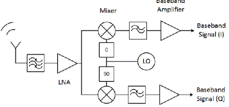
2.2.1 Homodyne receiver architecture ... 22
2.2.2 Heterodyne receiver architecture ... 23
2.2.3 Multiport interferometer receiver architecture ... 24
2.2.4 Six-port based radio receiver ... 26
2.2.5 Six-port based AOA detector ... 29
2.2.7 Six-port calibration ... 32
2.2.8 Pros and cons of six-port technique ... 32
2.3 Electromagnetic wave propagation and DOA detection ... 33
2.3.1 Electromagnetic wave propagation ... 34
2.4 DOA detection techniques ... 36
2.4.1 Amplitude difference of arrival technique ... 37
2.4.2 Phase difference of arrival (PDOA) technique ... 38
CHAPTER 3 MULTIFUNCTIONAL TRANSCEIVER FOR FUTURE RADAR SENSING AND RADIO COMMUNICATION DATA FUSION PLATFORM 3.1 System concept ... 40
3.1.1 Signal modulation scheme ... 40
3.1.2 Operation principles ... 42
3.2 TFMCW radar signal analysis ... 45
3.2.1 Ambiguity intervals ... 45
3.2.2 Multi-target detection ... 46
3.2.3 Estimation accuracy ... 50
3.3 System architecture and analysis ... 53
3.3.1 Overview of FCC Rule Making for DSRC ... 53
3.3.2 Experimental RadCom system specifications ... 54
3.3.3 Radar-Radio incompatibilities ... 55
3.3.4 Transceiver architecture ... 57
3.4 Simulations ... 59
3.4.1 RF circuit simulations ... 59
3.4.2 System-level simulations ... 61
3.4.4 Simulation results of communication mode ... 66
3.5 Prototyping and measurements ... 67
3.5.1 Tx Block ... 68 3.5.2 Down-converter block ... 69 3.5.3 AGC Loop ... 69 3.5.4 Tx and Rx antenna ... 70 3.6 System-level measurements ... 74 3.6.1 Radio communication ... 74 3.6.2 Radar sensing ... 80
3.7 Conclusion and discussions ... 89
CHAPTER 4 PARAMETRIC CHARACTERIZATION OF SIX-PORT INTERFEROMETER 4.1 Noise analysis ... 92
4.1.1 NF of multi-port demodulator ... 93
4.2 Conversion loss improvement ... 96
4.3 Equivalent mixer model ... 98
4.4 Conclusion ... 101
CHAPTER 5 UNIFIED RADAR-COMMUNICATION (RADCOM) MULTIPORT INTERFEROMETER TRANSCEIVER 5.1 System concept ... 102
5.1.1 Modulation scheme ... 102
5.1.2 Transceiver architecture ... 103
5.2 Operation principles of novel multi-port component ... 104
5.3 Prototyping and measurements ... 105
5.4 Conclusion ... 109 CHAPTER 6 DEVELOPMENT OF MILLIMETER-WAVE COMPONENTS
6.1 Hybrid structure based field rotation balun for millimeter-wave applications ... 110
6.1.1 Concept and structure of the balun ... 112
6.1.2 Prototyping and measurements ... 114
6.2 Wideband planar 180o hybrid coupler with non-interspersed ports ... 116
6.2.1 Proposed Topology of the 180o hybrid coupler ... 118
6.2.2 Theoretical analysis ... 119
6.2.3 Design of the proposed coupler ... 128
6.2.4 Prototyping and measurements ... 131
6.2.5 Conclusion: ... 136
CHAPTER 7 MILLIMETERWAVE MULTIFUNCTION MULTIPORT INTERFEROMETRIC RACEIVER FOR FUTURE WIRELESS SYSTEMS 7.1 Proposed multiport architecture ... 139
7.2 Ambiguity in AOA detection ... 145
7.3 Multi-function transceiver architecture ... 146
7.4 Calibration technique ... 148
7.4.1 Calibration in sensing mode ... 149
7.4.2 Calibration in radio mode ... 150
7.5 Prototyped transceiver ... 152 7.5.1 Tx block ... 153 7.6 Antenna ... 155 7.6.1 Rx block ... 157 7.7 System-level measurements ... 161 7.7.1 AOA detection ... 164 7.7.2 Radio communication ... 165 7.8 Conclusion ... 170
CHAPTER 8 2-D DIRECTION-OF-ARRIVAL (DOA) ESTIMATION SYSTEM THROUGH MULTIPORT INTERFEROMETRIC TECHNOLOGY
8.1 System scheme and analysis ... 172
8.1.1 Antenna topology and plane wave ... 173
8.2 Multiport interferometer topology ... 174
8.3 Signal processing algorithm ... 177
8.4 Plane wave simulations ... 177
8.5 Ambiguity issue and required distance between antenna elements ... 179
8.6 System-level simulations ... 181 8.7 Calibration technique ... 183 8.8 Implementation ... 187 8.9 Experimental prototyping ... 189 8.9.1 Antenna structure ... 190 8.9.2 Detector circuit ... 195 8.9.3 System Assembly ... 198
8.9.4 System level measurements ... 199
8.10 Conclusion ... 203
CHAPTER 9 DUAL-MODE COMMUNCIATION TRANSCEIVER ARCHITECTURE FOR BACKHAUL SMALL CELL APPLICATIONS 9.1 Multiple band/mode radio ... 206
9.2 Proposed architecture ... 209
9.3 Conclusion ... 214
CHAPTER 10 CONCLUSION AND FUTURE WORK 10.1 Conclusion ... 215
LIST OF TABLES
Table 3-1: Multi-target simulation results ... 50
Table 3-2: System specification ... 54
Table 3-3: Link budget analysis ... 55
Table 3-4: System simulation results for radio mode ... 65
Table 3-5: STD of range measurement ... 82
Table 3-6: STD of velocity measurements ... 83
Table 3-7: Measurement results ... 84
Table 3-8: Angle measurements ... 87
Table 3-9: Comparison of different RadCom schemes ... 91
Table 4-1: EVM simulation of six-port mixer ... 99
Table 4-2: EVM simulation of six-port mixer ... 100
Table 6-1: Comparison of the 180o hybrid couplers ... 131
LIST OF FIGURES
Figure 1-1: Typical scenario in the platform of ITS ... 1
Figure 1-2: Multiple radars with different operational zones for different applications ... 2
Figure 1-3: Antenna beam alignment application scenario ... 3
Figure 1-4: 5G network that extends to new applications ... 3
Figure 1-5: Advantages of multiple systems unification ... 4
Figure 2-1: Modulation scheme for integrated RadCom systems ... 20
Figure 2-2: Triangle linear FMCW ... 21
Figure 2-3: Homodyne receiver architecture ... 23
Figure 2-4: Heterodyne receiver architecture ... 24
Figure 2-5: Two different mixing processes ... 25
Figure 2-6: Two common topologies of passive junction for six-port receiver ... 26
Figure 2-7: Six-port radio receiver ... 28
Figure 2-8: Six-port AOA detector ... 30
Figure 2-9: Diode detector circuit schematic ... 31
Figure 2-10: Simulated (V-P) transfer function of the Schottky diode in ADS ... 31
Figure 2-11: Different DOA detection scenarios ... 36
Figure 2-12: DOA detection based on amplitude measurement ... 37
Figure 2-13: Antenna beam alignment based on amplitude measurement at two Rx elements ... 38
Figure 2-14: Wave propagation and geometrical arrangement of the receiving antenna ... 39
Figure 2-15: Phase difference of arrival at the antenna terminals ... 39
Figure 3-1: Spectrogram of power spectral density (PSD) of the operational signal ... 41
Figure 3-2: Typical application scenario. ... 44
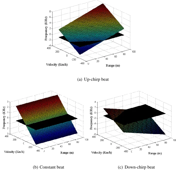
Figure 3-4: V-R diagram from a TFMCW radar. ... 48
Figure 3-5: Multi-target simulation scenario ... 48
Figure 3-6: PSD of the detected beat signals from simulation in Matlab. ... 49
Figure 3-7: Beat frequency pairing for multi-target detection ... 49
Figure 3-8: Variation of velocity estimation error as a function of threshold to noise level and SNR in simulation via Matlab ... 51
Figure 3-9: Variation of angle estimation error as a function of threshold to noise level or SNR in simulation via Matlab ... 53
Figure 3-10: Proposed transceiver architecture ... 58
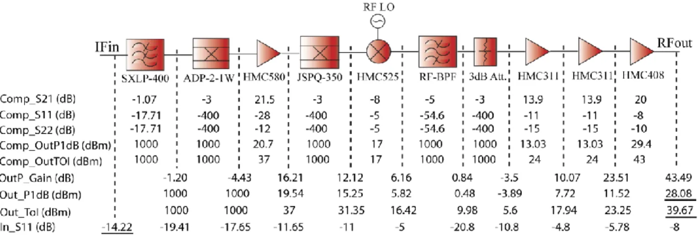
Figure 3-11: Chain budget simulation of Tx block ... 60
Figure 3-12: Chain budget simulation of down-convertor core in Rx block ... 60
Figure 3-13: Block diagram of multilayer simulation at system level via Ptolemy simulator in ADS package. ... 62
Figure 3-14: System simulation when operating in radar mode ... 63
Figure 3-15: Group delay of the RF BPF which is used in both Tx and Rx blocks in ADS ... 64
Figure 3-16: System-level simulation results when operating in communication mode ... 66
Figure 3-17: Prototyped building blocks of front-end ... 67
Figure 3-18: Cumulative graph of EVM spectrum of the signal at the output of Tx block. ... 68
Figure 3-19: Gain and NF of down-convertor block measured by NF analyzer. ... 69
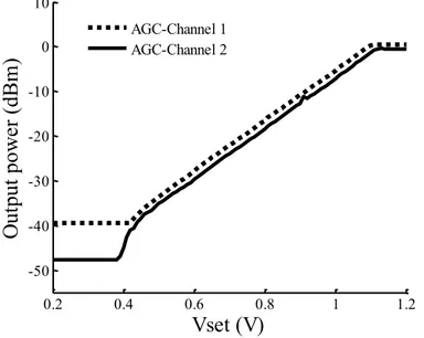
Figure 3-20: Gain control by two branches of AGC loop. ... 70
Figure 3-21: Building blocks of Tx antenna ... 71
Figure 3-22: S11 of transmitter antenna ... 72
Figure 3-23: Normalized radiation pattern of Tx antenna in two planes ... 73
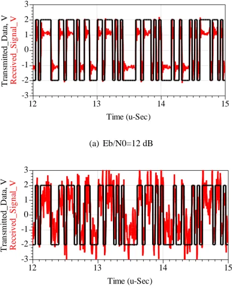
Figure 3-25: Measured constellation and EVM for different modulation schemes when system is configured to operate in radio mode ... 75 Figure 3-26: EVM and BER measurement results ... 76 Figure 3-27: System measurement in radio mode. ... 77 Figure 3-28: Measurement results in communication mode; Received signals are match-filtered by
an FIR filter with 4 taps and energy of unity. ... 79 Figure 3-29: Radar mode measurements with channel emulator ... 80 Figure 3-30: PSD of the measured beat signals with two different SNR ... 81 Figure 3-31: Measurement setup in lab ... 85 Figure 3-32: Range resolution and range profile measurement results ... 86 Figure 3-33: Angle measurement setup ... 87 Figure 3-34: Angle measurement results ... 88 Figure 3-35: Measurement results in position estimation ... 89 Figure 4-1: Proposed configuration for estimating the NF of a two port network... 93 Figure 4-2: Diagram for estimating the NF of six-port mixer ... 94 Figure 4-3: Calculated NF using the proposed equations. ... 96 Figure 4-4: Controlling the conversion loss of the six-port mixer via LO power and DC bias ... 98 Figure 4-5: Platform used in ADS simulations for validating the six-port mixer model ... 99 Figure 4-6: Comparison of BER between the six-port demodulator and the mixer model with
different values of P1dB in ADS simulations ... 100 Figure 5-1: Block diagram of the proposed transceiver architecture ... 104 Figure 5-2: Measurement setup ... 106 Figure 5-3: Measurement results of radio mode ... 106 Figure 5-4: Measured beat signals in frequency domain ... 107 Figure 5-5: Angle measurement results ... 108
Figure 6-1: Proposed balun structure ... 113 Figure 6-2: Prototype of the proposed balun ... 114 Figure 6-3: Measurement and simulation results of scattering parameters ... 115 Figure 6-4: The 180o hybrid coupler topologies ... 117 Figure 6-5: Implemented proposed topology in TEM structures ... 119 Figure 6-6: Four port network and T matrix ... 119 Figure 6-7: Comparison of the derived theoretical T parameters with the simulated ones... 122 Figure 6-8: Comparison of the derived analytical T parameters of the Schiffman phase shifter with
the simulated ones from ADS ... 124 Figure 6-9: Comparison of the simulation results of phase differences with the ones from analytical
equations for two different values of R ... 127 Figure 6-10: Bandwidth control over R for two different values of phase deviations (𝛿). ... 128 Figure 6-11: Comparison of phase differences between our proposed 180 deg hybrid topology with
the one proposed by Park in race [132], and the classic rat-race. ... 129 Figure 6-12: Comparison of amplitude imbalance ... 130 Figure 6-13: Prototyped hybrid on ceramic die ... 132 Figure 6-14: Measurement setup which is hold on mmWave probing station... 133 Figure 6-15: Measured and simulated amplitude components of S-parameters. ... 134 Figure 6-16: Comparison of measured and simulated phase differences. ... 135 Figure 7-1: The proposed multiport network ... 140 Figure 7-2: The comparison of the scattering matrix relationship between the conventional and
proposed multiport. ... 141 Figure 7-3: The unambiguous range of AOA estimation using the obtained M vector. ... 146 Figure 7-4: The proposed multifunction transceiver architecture ... 147 Figure 7-5: Modulation scheme of the Operational waveform ... 147
Figure 7-6: The prototyped transceiver ... 153 Figure 7-7: The block diagram of the Tx block for implementing the proposed transceiver. ... 154 Figure 7-8: Microscopic photograph of the prototyped MHMIC SIW cavity BPF. ... 155 Figure 7-9: Measured and simulated S-parameters of the BPF. ... 155 Figure 7-10: The prototyped Tx antenna with the SIW-WR10 adaptor. ... 156 Figure 7-11: Measured and simulated S11 of the antenna. ... 156 Figure 7-12: Measured and simulated series-fed antenna pattern in two planes. ... 157 Figure 7-13: Fabricated multiport circuit on ceramic substrate using MHMIC process. ... 158 Figure 7-14: Measured S-parameter of the multiport network. ... 159 Figure 7-15: Measured phase difference between input and output ports of the prototyped multiport. ... 159 Figure 7-16: Schematic circuit of the Schottky diode for simulation in ADS. ... 160 Figure 7-17: Prototyped detector circuit in measurement setup. ... 160 Figure 7-18: Measured RF-IF conversion gain of prototyped detector at different LO powers. . 161 Figure 7-19: System level measurement setup (without absorbers). ... 163 Figure 7-20: Received signal at the spectrum analyzer. ... 164 Figure 7-21: Measurement result of AOA detection. ... 165 Figure 7-22: The block-diagram of the system-level simulation platform in ADS and MATLAB. ... 166 Figure 7-23: The constellation diagram of the simulated receiver with non-idealities. ... 167 Figure 7-24: The EVM over different AOA. Calibration was done at angles 2 and 6 modulation of
16 QAM. ... 168 Figure 7-25: Measured constellation diagram ... 169 Figure 7-26: The EVM over SNR. Calibration was done when we had noise and SNR=20 dB. 169
Figure 8-1: Receiver antenna structure with four receiving elements and their interaction with the propagation vector of an incoming plane wave ... 173 Figure 8-2: Proposed multiport interferometer topology for 2D DOA parameter extraction . 175 Figure 8-3: Plane wave simulation scenario in HFSS ... 178 Figure 8-4: Plane wave simulation results at 60 GHz in HFSS ... 179 Figure 8-5: L_max values as a multiplication of free space wavelength.. ... 180 Figure 8-6: AOA detection system level simulation results from ADS. ... 181 Figure 8-7: Ptolemy Co-simulation panel of Circuit Envelop (for RF portions) and DF (data flow
for DSP) simulators in ADS ... 182 Figure 8-8: System level simulation results from ADS for angle detection in two dimensions for
different distances between antenna elements ... 182 Figure 8-9: Partitioning cells for calibration ... 186 Figure 8-10: Second configuration of the multiport interferometric architecture ... 187 Figure 8-11: Simulation results of amplitude component of the S-parameters of the designed eight-port interferometric network. ... 188 Figure 8-12: Simulation results of the phase differences (PHmkn) between different pairs of input
signals (m and k) at four output ports (n) ... 189 Figure 8-13: Fabricated phase shifters ... 190 Figure 8-14: Measured phase difference ... 190 Figure 8-15: Designed antenna configuration ... 192 Figure 8-16: Fabricated antenna with input transmission lines and V-Launchers ... 192 Figure 8-17: Measured and simulated S-parameters of the two elements of the antenna ... 193 Figure 8-18: Measured antenna pattern in H plane ... 194 Figure 8-19: Measured antenna pattern in E plane ... 194 Figure 8-20: Detector layout with components for simulation in ADS ... 195
Figure 8-21: Detector circuit with EMI filter with zero-bias Schottkey diode (MZBD-9161) .... 196 Figure 8-22: Return loss of the detector ... 197 Figure 8-23: Detected voltage vs input RF power at 58 GHz ... 197 Figure 8-24: The prototyped DOA detection system ... 199 Figure 8-25: Measurement setup for phase difference of arrival using the prototyped antenna .. 200 Figure 8-26: Measurement results for phase difference of arrival. ... 201 Figure 8-27: Test bed for system level measurements ... 201 Figure 8-28: System level measurement results at 58 GHz ... 202 Figure 9-1: Proposed dual-band dual-mode radio architecture ... 210 Figure 9-2: Proposed frequency planning diagram ... 210 Figure 9-3: Schematic view of the simulation in ADS ... 213 Figure 9-4: Simulation results in FDD mode ... 213 Figure 10-1: Frequency-time diagram of the chirp in two units (radar mode) ... 219 Figure 10-2: Proposed transceiver architecture ... 220 Figure 10-3: Spectra of the de-chirped radar and communication signals ... 220
LIST OF SYMBOLS AND ABBREVIATIONS
The list of symbols and abbreviations that are used throughout the thesis is presented below:
1-D One-dimensional
2-D Two-dimensional
ADC Analog-to-digital converter AGC Automatic gain control ASK Amplitude shift keying ACC Adaptive cruise control BPSK Binary PSK
CAD Computer aided design
CMOS Complementary metal-oxide-semiconductor CPW Coplanar waveguide
CTA Cross traffic alert
CW Continuous wave
DC Direct current
DDS Direct digital synthesizer DOA Direction of arrival DSP Digital signal processing
DSRC Dedicated short range communication DUT Device-under-test
EIRP Effective isotropic radiated power EMC Electromagnetic compatibility EMI Electromagnetic interference EVM Error vector magnitude
FCC Federal communication commission FDD Frequency division duplexing FDMA Frequency division multiple access FFT Fast Fourier transform
FMCW Frequency modulated continuous wave FPGA Field programmable gate array
FSK Frequency shift keying
ISM Industrial, Scientific and Medical ITS Intelligent transportation systems LCA Lane change assistance
LPF Low-pass filter LRR Long range radar
MHMIC Miniature hybrid microwave integrated circuits MMIC Multiple input and multiple output
NF Noise figure
OFDM Orthogonal frequency division multiplexing OOK On-off keying
PCB Printed circuit board
PN Pseudo-noise
PSD Power spectral density
QAM Quadrature amplitude modulation QPSK Quadrature phase shift keying RCS Radar cross section
SIW Substrate integrated (rectangular) waveguide SNR Signal-to-noise ration
SOLT Short-open-load-through SoS System on substrate SPR Six-port receiver SRR Short range radar TDD Time division duplex
TDMA Time division multiple access TOI Third order intercept
TRL Thru-reflect-line
VNA Vector network analyzer VSWR Voltage standing wave ration
LIST OF APPENDICES
CHAPTER 1
INTRODUCTION
1.1
Motivation and research background
Rapid evolution of radio technology has brought up many related applications to further simplify the human life in a variety of aspects. Intelligent transportation system (ITS) can be a good example in which cars are equipped with multiple sensors and they are able to share the collected information with other vehicles and the related infrastructures. Figure 1-1shows a typical scenario of ITS platform where vehicles are sensing their surroundings and communicating with each other as well. Co-existence of either sensors or radios can be mutually advantageous for both wireless functions. For instance, it helps building sensor networks with extended operational range and rather accurate estimations thanks to the redundant collected pieces of information. On the other hand, the sensory information can also help improving the communication quality by mitigating the multipath or Doppler Effect through beamforming or real time channel estimation or accurate carrier recovery, respectively.
Figure 1-1: Typical scenario in the platform of ITS, on-board vehicles either sense their environment or communicate the sensory data
In addition, the majority of ITS-required functions such as cross traffic alert (CTA), adaptive cruise control (ACC) or lane change assistance (LCA) can be realized by radio detection and
ranging (radar) sensors. Figure 1-2 shows the corresponding field of view and longitudinal zone of coverage by radars supporting these functions. Each of these desired functions demands for specific radar system’s specifications such as maximum and minimum detectable range, ranging and velocity resolution, and angular area coverage or measurement accuracy. These elements specify the characteristics of each individual part of the whole radar system, i.e., from signal generator at back-end to transceiver structure at radio frequency (RF) front-end and antenna. Therefore, three types of automotive radars have emerged, namely, long range radar (LRR), middle range radar (MRR) and short range radar (SRR).
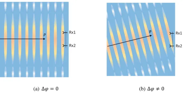
Figure 1-2: Multiple radars with different operational zones for different applications Antenna beam alignment systems can be considered as another example which requires co-existence of multiple angle detection sensors. Within such systems, angle of arrival (AOA) detection of the incoming signal beam can help aligning the high gain antennas in high data rate point-to-point radios. In Figure 1-3, the antenna alignment and misalignment that may yield a complete communication failure is sketched. One dimensional (1-D) AOA estimation techniques have already been developed, but for very high gain antennas with pencil beams, angle estimation in two dimension is required in emerging applications such as high-speed backhaul radio links.
Figure 1-3: Antenna beam alignment application scenario; (a) Antennas are aligned, (b) There is a misalignment between pair of antennas
Moreover, by the advent of 5G technology, a user centric network is to be developed where people are connected to machines which are connected to the other machines and can operate in semi-autonomous manner. Figure 1-4 shows a typical scenario within future 5G network where multiple sensor and radios operate in a cooperative mode.
Figure 1-4: 5G network that extends to new applications
However, in all of the above-mentioned examples, assembling multiple systems for multiple applications on a single platform may end up expensive or complicated realization. Therefore, the interesting concept of integrating multiple wireless devices into a single multifunctional system
has come into view, in sake of design simplicity, better efficiency and lower cost, compact size, versatile functionality, low power consumption and shorter response time, as illustrated in Figure 1-5.
Figure 1-5: Advantages of multiple systems unification
In the framework of this thesis, our attention has been drawn into several important contexts of integrated systems, including Radar-Communication (RadCom), 2-D AOA estimation and finally dual-band and dual-mode radio architectures. The research flow in these domains is concisely reviewed next.
In the 1990s, the concept and technology of ITS was introduced and studied for the first time [1]. ITS encompasses a broad range of technologies, supporting two indispensable functionalities, namely environmental sensing and sensory-data communicating services including vehicle-to-vehicle (V2V) communications. ITS-America, ERTICO-ITS in Europe and ITS-Asia Pacific are all leading advocates and consortiums for these technologies and support ongoing research efforts that have already targeted a rapid development of ITS. Nevertheless, the ITS development has not achieved all its predefined objectives and potentials even though this concept is now more than twenty years old. That is because a successful marketing of ITS demands for low cost, highly efficient, and small form factor vehicular products while realizing a variety of required functions
also demands for utilizing different expensive sensor and radio systems. On another hand, the emerging technology of autonomous driving cars are supposed to operate based on three principles, i.e., sensing the environment, mapping the road and negotiate with other road users. Consequently, radios and radar sensors are fundamental parties of this future technology. Assembling different system modules on a single platform should not be the optimum solution. Therefore, significant research activities for developing sensor fusion techniques [2] and integrated radar and communication (radio) devices through transceiver unification [3] have come into play. The concept of radar-communication unification originates mainly from [4], which is further developed and termed as “RadCom” in this thesis for simplicity.
Interestingly, the search for the most efficient solution about multifunctional systems has progressed in a few different directions. The differentiating aspect of all reported outcomes is related to the integration scheme that involves waveform and the associated transceiver architectures. Furthermore, such a multifunctional integration may take part in frequency domain through either multicarrier or spread spectrum techniques [5-13], or in time domain through time-division technique [14-16]. To situate this work in the ongoing context of this research area, the nature and the fundamental concepts of the reported research are categorized and briefly reviewed as follows.
In [17], the mode of sensing is separated from the function of communication in frequency domain. In this case, a narrow band on the first null of spectrum of the pulsed radar between the main lobe and the first side lobe is dedicated to communication on a single carrier. This scheme would be able to sense merely the range of a detected object. Unfortunately, high data rate communications are not possible since a sharp band-pass filter (BPF) with absolute narrow communication bandwidth is required for suppressing the radar interfering signals.
Ultra-wide-band (UWB) systems are generally developed for short-range applications. They are highly capable of communication due to their large Shannon capacity and extreme immunity to Rayleigh fading, in addition to radar sensing thanks to a large capability of penetration as well as a reduced clutter. These advantages can be combined into one single design platform, using various spread spectrum techniques such as direct sequence [6, 7, 9, 12, 13], code-hopping [10], time-hopping [8] and frequency modulated (FM)-UWB [5]. In [11], both radar and communication modes make use of gated linear frequency modulated (LFM) signals but with opposite chirp slopes.
They can be combined and transmitted simultaneously through a single antenna. For data communication, the carrier can be modulated by phase shift keying (PSK) technique. At the receiver end, two separate blocks receive radar and communication signals that are distinguished by oppositely circular polarized antennas, i.e., right versus left handed.
Radar-radio integration through coding has some major advantages. Both functions can operate simultaneously with a minimum interference due to the orthogonality of pseudorandom noise (PN) codes applied in [7, 9, 12, 13] or the quasi-orthogonality of up- and down-chirps applied in [11]. In addition, these systems are highly immune against jamming and interception. However, they require considerable spectrum resources in an inefficient manner. Besides, rather limited information can be obtained through the radar mode and the overall transceiver is made expensive and complex as well.
Simultaneous radar and radio operation on the basis of a single transceiver was also realized by the amplitude modulation (AM) of an FMCW radar signal [18]. In this so-called AM-FMCW technique, information is encoded on radar signal. Therefore, radar frequency and channel are reused for data transmission without disturbing the sensing functionality. Within the sensing mode, the reflected signal from target is received and then filtered after down-conversion. The frequency component generated by modulation is suppressed by filtering and therefore, it does not impact the radar’s performance. For communication, the AM data receiver synchronizes the locally generated FMCW signal with received signal so that the frequency difference is locked at a desired IF frequency. In this way, the frequency component that conveys information can be discriminated for AM demodulation. The major drawback of this integration scheme is that the operation is based on master-slave manner. In fact, the AM receiver (slave side) is not able to send data whereas the data transmitter (master side) on FMCW signal cannot receive any data from other units.
Joint or independent operation of a radio-radar fused system has also been proved to be feasible by separating those two functionalities in time domain [16]. This scheme is dedicated to applications in intelligent vehicle and highway system (IVHS). In this scheme, units in base-stations are able to sense the environment and communicate with tags that are only able to receive and transmit data. Two different modes of operation are allocated to different time-divided cycles. Furthermore, a mode-selective signal runs the VCO in transmitter to generate FMCW for radar mode and single frequency carrier for radio mode. In the radar mode, the operation principle is
identical to that of any FMCW radar. For the radio communication, base-stations operate in full-duplex mode. Carrier can be modulated by information data using amplitude shift keying (ASK) technique while for data reception from tags a pure carrier should be transmitted. Mobile tags can modulate this carrier by phase shift keying (PSK) to send data to the base stations. FMCW radar is also integrated sequentially with communication by frequency shift keying (FSK) technique [19] or even by spread spectrum scheme [20].
Radar-radio integration can also be implemented on multicarrier architectures like orthogonal frequency division multiplexing (OFDM). OFDM radar signals are not suffering from range-Doppler coupling issues. In addition, UWB-OFDM radars outperform counterparts based on UWB spread spectrum signals, due to higher spectral efficiency and pulse diversity potential. The design process of such a multifunctional system was described by [21]. In [22], the basic concept of radar and data communication fusion using OFDM signals was detailed and evaluated through simulation. For radar applications, the information of radar signal can be obtained from received signal after match filtering. On the other hand, for data communication, serial data is divided into blocks and bits on each block are mapped on sub-channels of OFDM symbol using On-Off keying (OOK). However, OFDM systems require high-peak-to-average-power-ratio (PAPR) and are sensitive to Doppler spreading. Accordingly, complex frequency synchronization and potential linearity requirement would significantly increase their system cost.
A rather complete time-domain scheme was proposed and developed in [14, 23] through an innovative waveform technique, by which all on-board units are able to either communicate or sense the environment. When radar mode comes into play, up- and down-chirp signals are separated in time with a single-frequency signal in the middle of a time division scheme. This would immune the conventional FMCW radar against interference. Radio cycle follows these three time slots and consists of a single carrier with constant frequency that can be modulated in either phase or amplitude. Using this scheme, a joint operation of radar and radio modes with minimum interference was studied and demonstrated. However, this system would be able to detect only the range and velocity of the target in sensing mode.
Either time or frequency domain based integration scheme possess specific advantages or disadvantages that may make them preferable depending on the desired functionality and tolerable cost or complexity of the system.
The main advantage of time division over frequency division is the efficient usage of frequency resources, especially around narrow available frequency bands. With the former approach, the whole band might be allocated to radar sensing in support of a good resolution during the radar cycle while the same band can be divided into several narrower segments to be used for communication between units in different cells. Moreover, the separation of distinct operational signal into different time slots would allow for avoiding the complexity of signal processing when a plurality of functions is desired to be accomplished all together.
However, the major drawback of time-domain integration scheme is the necessity of synchronization. Indeed, units in the same system cell should use the same carrier frequency, and the reference clock signal of all units in a system cell should be synchronized. This can be done, using the timing information of global positioning system (GPS) or even other techniques such as network time protocol [24].
In this thesis, the time-domain based integration scheme has been selected for further research and development with the main focus on improving RF front-end of multifunctional transceivers through unifying essentially different types of architectures for different functions. The principles of this integration scheme are discussed more in detail throughout the following chapters.
In all radio-radar integrated systems schemes, the well-known techniques of wireless sensing and communications are incorporated. The main challenge remains for the development of transceiver architectures in which techniques for RF component unification or sharing should be applied to avoid high cost and complexity. This issue becomes rather important when more functions are desired to be added to these multi-functional systems.
The radar associated functions in most reported RadCom schemes are limited to merely range and velocity estimation, and rarely a solution is presented for complete object positioning via an additional function of angle detection, while this is an indispensable function of automotive radar systems. Nevertheless, the technique of time-difference-of-arrival (TDOA) is adopted in RadCom system proposed by [25] which uses pulse-position-modulation (PPM) as operational signal and is capable of complete localization, and also the concept of incorporating OFDM RadCom systems with multiple-input-multiple-output (MIMO) architectures is discussed through simulations in [26].
Existing techniques of angle detection demand for utilizing at least two receiver channels. Hence, incorporating them in RadCom systems may undesirably augment the complexity in implementation unless every portion of the transceiver is unified or shared if possible. This research problem is explored deeply in this thesis and an improvement is made through adding a function of angle detection along with complete system characterization based upon the time-domain integration schemes and the corresponding transceiver architectures.
However, the reported transceiver schemes for integrated RadCom systems were mostly based on conventional heterodyne (low-IF) or homodyne (zero-IF) architectures [14, 15, 27, 28]. Through these architectures, integration of multiple systems can be achieved mostly through 1) time sharing of different parts of the Rx or Tx blocks between corresponding operational modes or 2) dealing with the incompatibilities between different modes regarding essential system specifications or channel characteristics. Furthermore, such architectures can be inevitably complex for implementation when additional functions such as angle detection are to be compromised with the existing functions, because multiple receiver paths would have to be added. This can eventually augment the circuit complexity especially at the final down-conversion/mixing stage in the Rx block. Thus, the strategy of unification instead of only sharing different parts of transceiver is concerned in this thesis when additional functions are to be incorporated.
Apart from the heterodyne and homodyne transceiver architectures, the technique of multiport interferometer has been applied to the design of distinct radio and sensing systems. The considerable advantages of this technique have been demonstrated for variety of applications, including modulation [29, 30] and demodulation [31-33] of carriers for communication purposes or range, velocity and angle estimation for sensing purposes [33-36].
Subsequent to the early demonstration of the multiport technique for network analyzer applications by Engen and Hoer around early 1970s [37-39], the six-port interferometer was demonstrated for the first time to be capable of quadrature demodulation when applied in the receiver (Rx) block of a communication system by [40] in early 90s. Subsequently, the same topology was employed to operate as a down-converter in the Rx block of radar systems where the FMCW signal would be de-chirped [41, 42]. Furthermore, simple, and low-cost AoA estimation systems were developed via six-port technique [43-45] with very high accuracy thanks to the excellent phase resolution in processing of the input signals within passive multiport network [46].
In addition, positioning systems with accuracy in the range of micrometer were demonstrated with this technique for small vibration detection in industrial areas [36] or patient respiration monitoring in health care centers [47]. On the other hand, it was used in the Tx block for direct modulation of the carrier signal [29, 30].
Like any other solution, six-port technique possesses pros and cons which are discussed briefly in the following. The core of the multiport interferometers is the passive network of couplers and/or phase shifters. Therefore, a wide fractional bandwidth is easily achievable. In addition, the required LO power for up/down conversion purposes is much less than the regular mixer-based up/down converters because it operates with square law diode detectors [48]. These benefits are very important for system applications around millimeter wave frequency bands [35]. Because of the very simple signal processing required in this technique, the systems based on multiport architectures do not suffer from heavy computation burdens. On the other hand, poor sensitivity of detectors restricts the dynamic range of six-port based receivers [49, 50]. In addition, such architectures demand for an appropriate calibration technique for mitigating the effects of the circuit non-idealities in practice. Therefore, various calibration techniques have been reported for six-port based systems with different applications that are categorized in [50]. In [49], a solution has been presented for diode linearization and calibration that extends the dynamic range of the receiver.
Due to the remarkable advantages of the multiport technique and the plurality of available ports, the multiport architectures can be a promising candidate for multifunction transceivers. Therefore, this interferometric architecture besides the heterodyne or homodyne ones are mainly concerned in this thesis to be further developed for the purposes of unifying the transceivers of multiple systems.
As it is mentioned, one of the challenging issues in devising an architecture for the integrated multifunctional transceiver is the intrinsic incompatibilities that either inherits from the absolute different system specifications or naturally exist in different propagation channels. For instance, the propagation path loss or required signal to noise ratio (SNR) can be significantly different for radar and radio signals that should be respected in designing the RF front-end circuitry. In other words, whatever the integration strategy would be, i.e., component sharing or unification, these incompatibilities should be dealt with which demand for complete characterization of these three types of the above-mentioned transceiver architectures.
The heterodyne or homodyne based architectures have been already characterized, whereas some aspects of multiport interferometric structures are not completely investigated yet. Therefore, multiport architectures are analyzed within this thesis in terms of noise figure (NF), conversion loss and intermodulation (IM) products that should essentially be known in transceiver design. Moreover, the capabilities of existing multiport architectures are investigated for integration of multiple functions and novel passive networks are presented that makes functional integration feasible. Furthermore, appropriate calibration techniques are presented where the existing techniques were no longer appropriate with the new proposed multiport architectures.
1.2
Objectives
The overall objective of this PhD thesis work is to propose and develop low-cost integrated multifunctional systems. Sensing and communicating as the ubiquitous application of radio technology were selected for integration. The emphasis is on radar type of sensors and on the integration of radar related functions such as range, velocity and angle detection with the function of communication. Moreover, the development of multifunction sensors and also multiband radio transceiver architectures are also considered in this thesis. Three specific objectives stem from this general objective as follows:
1) Improve the state-of-the-art time domain RadCom scheme and the corresponding transceiver though adding more functions such as angle detection.
2) Develop transceiver unification strategies for integrating multiple functions through multiport interferometric techniques.
3) Propose, model and characterize innovative RF components such as couplers and Baluns for millimeter wave applications which are indispensable for the transceiver unification.
The long-term objective of the projects conducted in this PhD thesis is to build up a ground for future systems-on-chip specifically for millimetre-wave applications. Transceiver unification techniques proposed in this thesis can contribute significantly to the simplification, cost and size reduction of the multifunction systems-on-chip (SoC) or systems-on-substrate (SoS). The principles of the proposed techniques in this thesis are not limited to a specific fabrication process such as printed-circuit-board (PCB) or Miniaturized-Hybrid-Microwave-Integrated-Circuit
(MHMIC) and can be realized using advanced technique of complementary metal-oxide-semiconductor (CMOS).
1.3
Methodology
The main approach in this thesis is to develop first multifunctional system concepts which may involve operational waveform schemes, RF transceiver architectures as well as signal processing techniques. The developed concepts are assessed first through system level simulations upon theoretical analysis. The systems are also prototyped and measured to prove their actual or true functionality. The latter step could inevitably include some engineering aspects which may not be explained in detail within this research thesis.
1.3.1 Improvement of the state-of-the-art RadCom transceiver
The functionality of the state-of-the-art time domain integrated RadCom transceiver has been limited to distance and velocity estimation when operating in radar mode. Moreover, such scheme has not been completely characterized in terms of required signal to noise ratio and object detection in multi-target scenarios. The ability of beam direction estimation not only qualifies system capability in individual radar mode, but is also considered as a contribution to joint mode. For example, the information about beam direction can be used in radio mode for beam forming purposes. With the main objective of incorporating the additional function of angle detection to other ones of range and velocity estimation besides communication, and also enhancing the range resolution, the RadCom system is studied, characterized and implemented to prove the concept. The following steps are taken to accomplish these goals:
1) Waveform scheme and the corresponding transceiver are modified for AOA estimation and
higher data communication rate.
2) A signal processing solution is presented for multiple target detection.
3) The system incompatibilities in different modes of operation for different functions are
completely studied.
4) The desired waveform is realized by a combination of software-defined direct digital