HAL Id: hal-02083894
https://hal-univ-rennes1.archives-ouvertes.fr/hal-02083894
Submitted on 7 Jul 2020
HAL is a multi-disciplinary open access
archive for the deposit and dissemination of
sci-entific research documents, whether they are
pub-lished or not. The documents may come from
teaching and research institutions in France or
abroad, or from public or private research centers.
L’archive ouverte pluridisciplinaire HAL, est
destinée au dépôt et à la diffusion de documents
scientifiques de niveau recherche, publiés ou non,
émanant des établissements d’enseignement et de
recherche français ou étrangers, des laboratoires
publics ou privés.
Real Compact and Reconfigurable Antennas
D-T Phan-Huy, Yvan Kokar, K. Rachedi, Patrice Pajusco, Ali Mokh, T.
Magounaki, R. Masood, C. Buey, P. Ratajczak, N. Malhouroux-Gaffet, et al.
To cite this version:
D-T Phan-Huy, Yvan Kokar, K. Rachedi, Patrice Pajusco, Ali Mokh, et al.. Single-Carrier
Spa-tial Modulation for the Internet of Things Design and Performance Evaluation by Using Real
Com-pact and Reconfigurable Antennas. IEEE Access, IEEE, 2019, 7, pp.18978-18993.
�10.1109/AC-CESS.2019.2895754�. �hal-02083894�
Single-Carrier Spatial Modulation for the
Internet of Things: Design and Performance
Evaluation by Using Real Compact and
Reconfigurable Antennas
D.-T. Phan-Huy1, Member, IEEE, Y. Kokar2, K. Rachedi3, P. Pajusco4, A. Mokh2, T.
Magounaki1, R. Masood4, C. Buey1, P. Ratajczak1, N. Malhouroux-Gaffet1, J.-M. Conrat1, J.-C. Prévotet2, A. Ourir3, J. de Rosny3, M. Crussière2, M. Hélard2, Member, IEEE, A. Gati1, T. Sarrebourse1, M. Di Renzo5, senior Member, IEEE
1Orange Labs Networks, Châtillon, 92326 France
2INSA Rennes, CNRS, Institut d'Electronique et de Telecommunication de Rennes, UMR 6164, University of Rennes 1, 35000 Rennes, France 3Institut Langevin and Ecole Supérieure de Physique et de Chimie Industrielle, CNRS, 75005 Paris, France
4Institut Mines Telecom Atlantique, 29238, Brest, France
5Laboratoire des Signaux et Systémes, CNRS, University of Paris-Saclay, CentraleSupélec, University of Paris-Sud, 91192 Gif-sur-Yvette,
France
Corresponding author: D.-T. Phan-Huy (dinhthuy.phanhuy@orange.com)
This work was supported in part by SpatialModulation project under the French Research Agency Grant ANR-15-CE25-0016.
ABSTRACT In this paper, for the first time, we propose two new solutions to boost the data rate between small connected objects such as glasses and cams and the 5th generation (5G) mobile network, based on spatial modulation, single carrier waveform, compact reconfigurable antennas at the object side and massive multiple input multiple output (M-MIMO) at the network side. In the first new wireless communication system, a “transmitting object” uses transmit spatial modulation with a compact reconfigurable antenna and a constant envelop amplifier to transmit in high data rate with a low complexity and low power consumption. The space-time digital processing capability of the M-MIMO 5G base station is used to detect such signal. In the second new wireless communication system, a “receiving object” uses receive spatial modulation, a compact multiport antenna and a low complexity detection algorithm to receive in high data rate with a low complexity signal processing. The space-time beamforming capability of the M-MIMO 5G base stations is exploited to deliver a signal that is pre-equalized enough to be detected by the object. For the first time, we present experiments showing that M-MIMO allows for the re-introduction of single carrier modulation waveform. For the first time, we present performance results obtained with real existing compact antennas and compact reconfigurable antennas, showing that the two new communication systems outperform conventional modulation in terms of energy efficiency and complexity.
INDEX TERMS Spatial modulation (SM), receive antenna shift keying (RASK), beamforming, multiple input multiple output (MIMO), Reconfigurable Antennas, Compact Antennas.
I. INTRODUCTION
Future mobile networks of the 5th generation (5G) will provide a wireless connection to the Internet-of-Things (IoT) [1]. Among connected things, some, like connected glasses, connected cameras and connected watches, will need to transmit or receive video streams at a high data rate. The 3rd Generation Partnership Project (3GPP) has already started to lower down the cost and the power consumption of devices for connected objects by reducing the number of Radio
Frequency (RF) chains (for transmission) and reducing the number of RF amplifiers [2].
Recently, it has been shown that, for some high signal to noise ratios values, and still with a single RF chain at the transmitter side, by using transmit spatial modulation [3] with conventional arrays of antenna elements [4], one can achieve a higher spectral efficiency than by using a conventional modulation with the same single RF chain [5]. In transmit spatial modulation systems, in addition to the
data stream sent using a conventional Pulse shape Amplitude Modulation (PAM), an additional data stream is sent by switching the transmit antenna element, every symbol period. The index of the current transmit antenna element encodes binary information. Previous studies on transmit spatial modulation are focused on conventional arrays: [6] analyzes solutions based on spatial modulation that exploit the diversity gain of the conventional antenna array and [7]-[14] provide preliminary results on the performance of transmit spatial modulation based on experimental data obtained with conventional antenna arrays. For more information on transmit spatial modulation, please refer to the survey papers [15]-[19].
In receive spatial modulation systems such as the ones studied in [20], in addition to sending a conventional PAM, the transmitter sends an additional data stream by focusing towards one antenna of the receiver among several, every symbol period. The index of the target antenna encodes binary information. A simple receiver can be used to demodulate the two streams [21]-[23].
Other works on reconfigurable antennas [24]-[26] suggest that one can transport more bits than with a SISO system by using a reconfigurable antenna. In this case, instead of switching between antenna elements, the transmitter switches between radiation patterns. The advantage of these solutions is that they are more compact in size. The limitation of these techniques is the non-orthogonality of the radiation patterns, and up to now, no complete performance study with real and existing compact antennas has been performed to verify the advantage of such antennas.
In parallel, 5G envisions the development of massive arrays [28]-[30] at the network side, with hundreds of antenna elements. These Massive Multiple Input Multiple Output (M-MIMO) antennas benefit from higher beamforming and spatial multiplexing gains [28][29], or reduced complexity in the demodulation [30].
In this paper, for the first time, we introduce and make a complete performance evaluation of two new communication systems illustrated in Figure 1, for uplink and downlink communications, respectively, between objects with compact antennas and a base station with M-MIMO antenna array. In the uplink, transmit spatial modulation is used, and the object antenna is a compact reconfigurable antenna (either a multiport switchable antenna or a monoport reconfigurable antenna), whereas in the downlink, receive spatial modulation is used and the object antenna is still a compact antenna but multiport only in the current implementation. These two systems are compared to systems using conventional modulation schemes as well.
FIGURE 1. Transmit and receive spatial modulation for connected objects
The paper is organized as follows: Section II recalls the transmit and receive spatial modulation concepts and illustrates these concepts with visual experiments. Section III and IV present the performance evaluation study for transmit spatial modulation and receive spatial modulation, respectively.
The following notation is used throughout the paper. If ∈ ℂ, then | | is its module, arg ( ) is its phase in radians,
∗ is its conjugate, ℛe( ) is its real part and Im( ) is its
imaginary part. If ∈ ℂ × , then is the
transpose-conjugate of and ‖ ‖ = ∑ ∑ , . If ∈
ℂ ×
, then ‖ ‖ = ∑ . [ , ] is the set of integers between and , including and . j = −1. We define the set ( ), , and as follows:
( )= { ( )∈ {0,1} × | ∈ [1, ]; = log ( ); ∑ ( )2 = }; = { √ ,√ , √ , √ }; = ( ) , n ∈ ⟦1; 8⟧ ; = ( ) √ ∈ [0,3] and ∈ [0,3]}.
II. TRANSMIT AND RECEIVE SPATIAL MODULATION CONCEPTS
A. TRANSMIT SPATIAL MODULATION
In this section, we recall the concept of transmit spatial modulation and illustrate this concept with a visual experiment illustrated in Figure 2.
During the communication, the transmitter activates one radiation pattern among = 2 distinct ones. Each radiation pattern is associated with a distinct binary sequence of bits, according to a pre-defined pattern-to-bit mapping rule. The rule is known at both the transmitter and the receiver sides. As in most wireless communication systems, the transmitter sends pilots to train the receiver. More precisely, the transmitter activates each of its radiation patterns
Transmit spatial modulation
Receive spatial modulation Network side:
Massive MIMO antenna and advanced signal processing
Object Side: Compact antenna, energy
efficient and low cost signal processing
alternatively, so that the receiver can estimate and store the propagation channel associated with each pattern. Then, the transmitter performs an actual data transmission as follows. A long binary sequence is cut into sub-sequences of bits. To transmit a particular sub-sequence, the transmitter activates the pattern that corresponds to the sub-sequence, using the pattern-to-bit mapping rule. The receiver detects the pattern that has been used by comparing the current received channel with the stored channels. The receiver converts the detected pattern into a sub-sequence of bits using the pattern-to-bit mapping rule. Note that, transmit spatial modulation can be combined with a conventional modulation.
FIGURE 2. Experimental set-up
FIGURE 3. The 8 ports of the transmitter, their corresponding radiation patterns and their corresponding 3-bit sequences
As illustrated in Figure 2, our visual experiment involves an 8-port compact antenna at the transmission side and a 64-element M-MIMO antenna at the receiver side. The transmitter emits a signal with carrier frequency of 2.45 GHz with one antenna port among the = 8 available, thanks to a switch. In this case, a pattern encodes = 3 bits. As illustrated in Figure 3, the 8 radiation patterns
corresponding to the 8 ports of this antenna are distinct. Figure 3 also provides the mapping rule between patterns and 3-bit sequences.
As illustrated in Figure 2, the 64 elements of the M-MIMO antenna are positioned on a grid of 8 lines and 8 columns and connected to a real-time channel sounder. Figure 4 illustrates the graphical interface of the sounder. The top of Figure 4 illustrates the result of a previous channel training phase. For each of the 8 radiation patterns, the spatial signature (i.e., the matrix of 8 by 8 estimated channel amplitudes) is stored and displayed in color scale. Each spatial signature is associated with a pattern and a 3-bit sequence. The bottom of Figure 4 illustrates the data transmission. A 3-bit sequence is transmitted by activating one radiation pattern among the 8 available. The channel sounder displays the current spatial signature (i.e., the actual 8 by 8 matrix of amplitudes of the current channel) in a color scale, computes the correlation of this matrix with the 8 stored matrices, determines the pattern that maximizes the correlation, and converts it into the detected 3-bit sequence, using the pattern-to-bit mapping rule. As illustrated in a video [32], all these steps are done in real time. In [32], even though the channel training is done only once at the beginning of the video, the detection remains robust for a long time period. This is thanks to the large size of the 8 by 8 matrices on which the correlation is performed. This illustrates one of the advantages of using M-MIMO at the network side.
Note that the training phase of spatial modulation is equivalent to the channel estimation phase for a conventional single carrier modulation. Both modulations require the transmission of pilot symbols during these phases, with the same periodicity (enough to track the channel variation).
FIGURE 4. Graphical interface of the M-MIMO real time channel sounder
B. RECEIVE SPATIAL MODULATION
modulation and illustrate this concept with a visual experiment depicted in Figure 5.
The receiver has = 2 antenna ports with distinct associated radiation patterns. Each radiation pattern is associated with a distinct binary sequence of bits, according to a pre-defined pattern-to-bit mapping rule. The rule is known at both the transmitter and the receiver sides. Channel reciprocity based beamforming (BF) as implemented in time division duplex (TDD) mode systems is used in order to target one antenna of the receiver among . As in any channel reciprocity based BF system, during the training phase the receiver sends distinct pilots from its distinct ports so that, for each port, the transmitter can: 1) estimate the channel, and 2) compute and store the precoder that enables to beamform towards this particular port. Then, the transmitter performs data transmission as follows. A long binary sequence is cut into sub-sequences of bits. To transmit a particular sub-sequence, the transmitter uses the stored precoder that beamforms towards the pattern corresponding to the considered sub-sequence. Finally, after detecting the port that is the current target of the beamforming (for instance by identifying the port that receives the strongest power), the receiver converts the detected pattern into a sub-sequence of bits using the pattern-to-bit mapping rule. Note that, this can be combined with a conventional modulation.
In our visual experiment, a transceiver and a receiver detailed in [33] are used with a carrier frequency of 2.48 GHz.
As illustrated in Figure 5, the transmitter is a uniform linear array (ULA) of 4 monopoles and the receiver is a ULA of = 4 “squeezed monopoles”. These monopoles are “squeezed” in the sense that they are close to each other by much less than half a wavelength and subject to coupling. In this experiment, the transmitter uses maximum ratio transmission (MRT) beamforming [34], and switches at a maximum speed of 125 kHz between the four different stored precoders, each precoder targeting a distinct “squeezed monopole”. In this example, the identity of the target “squeezed monopole” encodes = log ( ) = 2 bits. In parallel, the system transmits BPSK symbols.
FIGURE 5. Experimental set-up.
Figure 6 illustrates the resulting constellation of receive spatial modulation together with BPSK modulation. The positions of the two BPSK states in the complex I-Q domain are visualized by two drawings of targets. The I-Q symbol received by each of the = 4 monopoles of the receiver is plot for different realizations of the propagation channel. The joint detection of BPSK and the spatial modulation consists in determining the monopole that is closest to one of the two BSPK states. Figure 6 illustrates experimental measurements of the received I-Q symbols. The measurements are classified into 8 different categories illustrated by 8 different figures. For each category, the same BPSK symbol and the same spatial modulation symbol are detected. One can note that spatial modulation works even with these “squeezed monopoles”. This is due to the fact that for one monopole the other monopoles act as parasitic scatterers. This is known to create decorrelation, and is exploited as a design principle for compact multiport antennas as the ones that were presented in [35][36], and that will be used in the current paper for performance evaluation.
FIGURE 6. Experimental observations of the constellations for receive spatial modulation and BPSK modulation.
III. MASSIVE MIMO: AN ENABLER FOR SINGLE-CARRIER MODULATIONS
5G is based on multi-carrier modulation. Such modulation is not compatible with spatial modulation [17]. However, we believe that the introduction of M-MIMO antennas in 5G networks is an enabler for the re-introduction of single-carrier modulation in the future. In previous works [37][38], it has been shown that thanks to time reversal focusing with a large number of transmit antennas, the signal at the receiver is nearly echo-free. In [38], a single-tap receiver successfully demodulates a signal using a single carrier modulation,
within a 30MHz bandwidth centered at 1 GHz and using a 256 Quadrature Amplitude Modulation (QAM). However, this experiment was performed using an arbitrary waveform generator at the transmission side, and an oscilloscope at the reception side.
In this paper, we show recent experimental results obtained using the open-source hardware and software development platform Open Air Interface (OAI), and a rail moving with a Digital Servo Amplifier, SERVOSTAR 300, along with a Rosier servo motor controlling the movement. OAI is a wireless technology platform that offers an open-source software-based implementation of the Long Term Evolution (LTE) system spanning the full protocol stack of 3rd Generation Partnership Project (3GPP) standard both in Evolved Universal Terrestrial Radio Access Network (E-UTRAN) and Evolved Packet Core (EPC). The experiments were carried out using orthogonal frequency division multiplex (OFDM) frames at the carrier frequency of 2.68 GHz. Each OFDM symbol consists of 512 carriers, out of which 300 are filled with random QPSK symbols and the rest are set to zero. An extended cyclic prefix (ECP) of 128 samples is added to each OFDM symbol after the 512-point Inverse Fast Fourier Transform (IFFT). The sampling rate is 7.68 mega symbols per second, resulting in an effective bandwidth of 4.5 MHz. Ten subframes each with 12 ECP-OFDM symbols compose the TDD OFDM frame.
FIGURE 7. Experimental set-up, in NLOS.
In the experiment, the receiver sends pilots called sounding reference signals (SRS) in the uplink direction. The transmitter uses these pilots to estimate the uplink channel. Channel reciprocity is exploited to deduce the downlink channel. The transmitter precodes its downlink data and pilots with a maximum ratio transmission (MRT) precoder to beamform the signal towards the receiver. Note that MRT is equivalent to time reversal or the transmit matched filter pre-filtering applied to OFDM instead of a single-carrier modulation [33]. During the experiment, 15 different positions of the receiver are tested, along a rail,
and all in NLOS of the transmitter. For each position, the receiver measures the frequency response of the received beamformed channel thanks to the downlink precoded pilots. The measurements were carried out inside a controlled laboratory environment. Figure 7 illustrates the measurement setup.
FIGURE 8. 8-port transmit antenna.
FIGURE 9. NLOS propagation.
Figure 8 illustrates the radiation patterns of the 8 ports of the transmitter. Although, the antenna is compact, it exhibits patterns that are diverse. This antenna is therefore equivalent to an array of 8 low-correlated antennas.
Figure 9 illustrates the propagation environment during the experiments. Non-line-of sight propagation is chosen to create multi-path propagation. In such environment, the channel impulse response has several delayed taps. Hence, a single tap receiver trying to demodulate a single carrier modulation would suffer from inter-symbol interference. Finally, we apply an IFFT to the frequency response of the
received beamformed channel, to obtain the corresponding filter in the time domain.
FIGURE 10. Received beamformed channel for the 15th position of the UE.
Figure 10 illustrates the measured frequency response and the corresponding impulse response, for the received beamformed channel measured at the 15th position. We observe that the beamformed channel is nearly a single tap channel. We also evaluate the ratio between the useful signal and the inter-symbol interference (SIR) that would be undergone by a single tap-receiver demodulating a single carrier modulation at 5 MHz. As illustrated in Figure 11, for all tested positions, this value exceeds 20 dB. This is largely sufficient to support a single carrier modulation with 16 QAM. More precisely, for the worst case position (position number 3), we simulate the transmission of 1,500,000 random bits over a single carrier modulation transmission with a Raised Root Cosine (RRC) filter, 16 QAM, and a single tap receiver. For this simulation we chose an extreme value of Roll Off factor (0.001), to test the worst case scenario. We use the same simulation methodology detailed in [38], except that we use the current measured beamformed channel impulse response. The resulting measured bit error rate over 1,500,000 bits is zero. This means that the attainable BER, in this case, is estimated to be lower than 10-5.
FIGURE 11. SIR with single carrier modulation.
Receiver Transmitter Transparent Obstacle 5 m 6 m Rail a) Frequency response a) Impulse response
This confirms that current standards for mobile networks have the potential to support single carrier modulations, with bandwidths as large as several MHz. Note that, by applying maximum ratio combining (MRC) at the receiver side (instead of MRT at the transmitter side), in an uplink transmission (instead of a downlink transmission) we would have obtained the same result: the channel after equalization would have been single tap. This means that after a receive matched filter, the channel is single tap and compatible with a single carrier modulation and a single-tap detector.
In the next sections, M-MIMO is used with much more antenna elements than in the current sub-section. It is therefore a reasonable assumption to consider that the beamformed or equalized channel (using transmit matched filtering or received matched filtering) will be single tap, i.e., not frequency selective. As a consequence, to derive the beamformed channel, one just needs to study the frequency-flat channel over the carrier frequency. Therefore, in the next sections, we will directly use a frequency-flat channel model for our performance studies and assume that the equalized or pre-equalized channel does not introduce interference between successive symbols in the time domain.
IV. UPLINK TRANSMISSION: FIRST PERFORMANCE EVALUATION OF TRANSMIT SPATIAL MODULATION WITH REAL COMPACT RECONFIGURABLE ANTENNAS
In this section, for the first time, we present a complete performance evaluation of a wireless communication system using transmit spatial modulation with a real and existing compact reconfigurable antenna at the transmitter side and an M-MIMO antenna at the receiver side. The considered carrier frequency in this section is 2.45 GHz.
A. MODELS OF REAL COMPACT RECONFIGURABLE
ANTENNAS AND THE PROPAGATION CHANNEL At the base station side, we consider a ULA of = 64 elements spaced by half a wavelength as an example of M-MIMO antenna.
As for the object, two different real and existing compact reconfigurable antennas are considered and compared:
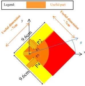
A multiport switchable antenna [36] illustrated in Figure 12-a) that can generate = 4 different radiation patterns, and that can therefore transmit = log ( ) = 2 bits by using spatial modulation; A monoport reconfigurable antenna [40] illustrated in Figure 13-a) that can generate = 2 different radiation patterns, and that can therefore transmit = log ( ) = 1 bit by using spatial modulation. The first one is half of the wavelength in size, whereas the second one only occupies one third. For both antennas, only one radiation pattern is activated at a time, either thanks to a
RF switch connected to the multiport antenna or by commuting the diodes of the reconfigurable antenna [40].
FIGURE 12. Compact multiport switchable antenna model.
The two-dimensional (2D) propagation models, for the multiport switchable antenna and the monoport reconfigurable antenna are illustrated in Figure 14 and Figure 15, respectively. For the two compact reconfigurable antennas, the complex gain function ( ) ( : ⟶ ) of each pattern p in direction angle is numerically characterized by using Finite Difference Time Domain (FDTD) full wave simulation. The moduli of the radiation patterns are illustrated in Figure 12-b) and Figure 13-b), for the multiport switchable antenna and the monoport reconfigurable antenna, respectively.
The spatial correlation between two radiation patterns and of the same antenna is a key parameter in spatial
b) 2-D radiation patterns, where is the angle of arrival or departure and is the antenna gain in the direction of for port
p
P1
P2
P3
P4
9.
6c
m
9.
6c
m
a) Antenna dimensions and convention for y
x x Legend: Useful part
| p ( )| si n ( )
modulation systems. The less correlated the patterns are, the more robust spatial modulation to noise is. The correlation is given by:
, = ∫ ( )
∗( )
∫ ( ) × ∫ ( )
Table I and Table II provide the correlations for the multiport switchable antenna and the monoport reconfigurable antenna, respectively.
FIGURE 13. Compact monoport reconfigurable antenna model.
FIGURE 14. Propagation model for the multiport switchable antenna.
FIGURE 15. Propagation model for the monoport reconfigurable antenna.
TABLEI
CORRELATIONS , BETWEEN ANTENNA PORTS P AND Q FOR THE
MULTIPORT SWITCHABLE ANTENNA
\q 1 2 3 4 1 1 0.0722 0.0593 0.0007 2 0.0772 1 0.0158 0.0522 3 0.0593 0.0158 1 0.0688 4 0.007 0.0522 0.0688 1 TABLEII
CORRELATIONS , BETWEEN ANTENNA PORTS P AND Q FOR THE
MONOPORT RECONFIGURABLE ANTENNA
\q 1 2
1 1 0.3190
2 0.3190 1
We consider a single carrier modulation communication. As explained in section III, thanks to the M-MIMO antenna and assuming that a matched filter is used at the receiver, we can limit the study to a frequency-flat channel and assume that the channel does not introduce interference between successive symbols in the time domain. The wireless propagation channel between one antenna port of the transmitter and one antenna element of the receiver can be modeled by a complex gain.
We define ∈ ℂ × as the channel between the object
and the base station. More precisely, let , be the
channel coefficient between the receive antenna ∈ [1, ] of the base station and the object when it is using the radiation pattern number ∈ [1, ]. , includes both the
wireless propagation and the radiation pattern .
Regarding the model used for multi-path propagation, we consider a 2D wireless propagation model, with random scatterers creating angular diversity in the channel. The
b) 2-D radiation patterns, where is the angle of arrival or departure and ) is the antenna gain in the direction of for radiation
pattern p
a) Antenna dimensions and convention for Legend: Useful part
2 cm 2 cm z y x Useful dimension ~ 5cm Useful dim ension~ 4c m | p ( )| co s( ) Pattern 1Pattern 2 P1 P2 P3 P4 9.6cm 9.6cm Multiport antenna x y
Massive MIMO antenna
: Angle of arrival … … … z z x y Scatterer q : Angle of departure
elements of the M-MIMO antenna are spatially correlated. The path ∈ [1, ] between the receive antenna of the base station and the connected object has a random complex gain ∈ ℂ , a random angle of departure ∈ [0,2π[ and a random angle of arrival ∈ [0,2π[ . is a Rayleigh fader with = 1/Q and and are uniformly distributed over [0,2π[. With these notations, the channel coefficient , is given by:
, = ∑ δ . ( ), (1)
where is a normalizing factor. We choose such that: ‖ ‖
= 1.
In other terms, the average channel power per SISO antenna link is unitary.
B SYSTEM MODEL
For the compact multiport switchable antenna, we compare five different schemes to send a sequence of bits, where, = … ∈ ( ), and = 4:
- “16QAM & Pattern = 1”; - “16QAM & Pattern = 2”; - “16QAM & Pattern = 3”; - “16QAM & Pattern = 4”; - “QPSK & SM4”.
For the compact monoport reconfigurable antenna, we compare three different schemes to send a sequence of bits, where = … ∈ ( ), with = 4:
- “8PSK & Pattern = 1”; - “8PSK & Pattern = 2”; - “QPSK & SM2”.
For all schemes, for each symbol period, the object sends a sequence of bits ∈ ( ) with a radiation pattern .
Among these > 0 bits, > 0 bits are sent using a complex modulation symbol ∈ , where is the pre-defined set of complex modulation symbols. ≥ 0 bits are sent using spatial modulation. So, the following holds:
= + .
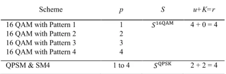
The definition of S, the values of , and are scheme-specific and provided in Table III and Table IV for the schemes with the multiport switchable antenna and the monoport reconfigurable antenna, respectively. Note that, for “16QAM & Pattern ” and “8PSK & Pattern ”, the radiation pattern p is fixed, and spatial modulation is unused ( = 0). On the contrary, for “QPSK & SM4” and “QPSK & SM2” schemes, the pattern p is variable and spatial modulation is used ( > 0).
TABLEIII
SPECTRAL EFFICIENCY R FOR THE COMPACT MULTIPORT SWITCHABLE ANTENNA (WITH P=4 STATES), IN NUMBER OF BITS PER SYMBOL PERIOD
Scheme p S u+K=r
16 QAM with Pattern 1 1 4 + 0 = 4 16 QAM with Pattern 2 2
16 QAM with Pattern 3 3 16 QAM with Pattern 4 4
QPSM & SM4 1 to 4 2 + 2 = 4 TABLEIV
SPECTRAL EFFICIENCY R FOR THE COMPACT MONOPORT RECONFIGURABLE ANTENNA (WITH P=2 STATES), IN NUMBER OF BITS PER SYMBOL PERIOD
Scheme p S u+K=r
16 QAM with Pattern 1 1 4 + 0 = 4 16 QAM with Pattern 2 2
16 QAM with Pattern 3 3 16 QAM with Pattern 4 4
QPSM & SM4 1 to 4 2 + 2 = 4
More precisely, in the “QPSK & SM4” scheme, as illustrated in Figure 16, during each symbol period, is sent using QPSK. Simultaneously, is sent using the corresponding pattern number (based on Table V).
TABLEV
PATTERN-TO-BITMAPPINGRULE
00 10 01 11 p 1 2 3 4 Object Massive MIMO antenna SM4 Modulation (switches radiation pattern) 01 Wireless propagation Compact multiport antenna Base station QPSK Modulation Bits Joint QPSK-SM4 demodulation 01 01 01 Bits Spatial bits Spatial bits
FIGURE 16. “QPSK & SM2” system model for the monoport compact antenna
Object Massive MIMO antenna SM2 modulation (switches radiation pattern) 1 Wireless propagation Compact multiport antenna Base station QPSK modulation Bits Joint QPSK-SM2 demodulation 01 1 01 Bits Spatial bit Spatial bit
FIGURE 17. “QPSK & SM2” system model for the monoport compact antenna.
FIGURE 18. Constellations for 16QAM, “QPSK & SM4”, with same average radiated power
In the “QPSK & SM2” scheme, as illustrated in Figure 17, during each symbol period, is sent using QPSK modulation. Simultaneously, is sent using the corresponding pattern number (pattern = 1 corresponding to Bit “0” and = 2 corresponding to Bit “1”).
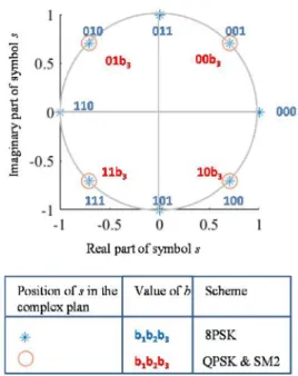
Figure 18 and Figure 19 illustrate the mapping between bits and symbols for the schemes with the multiport antenna and the reconfigurable antenna, respectively. Note that with
the chosen definitions, [| | ] = 1 for all schemes. In other terms, all schemes radiate the same transmit power per symbol, on average.
FIGURE 19. Constellations for 8PSK, “QPSK & SM2”, with same average radiated power
For any scheme, we define as follows: = { ( )∈ {0,1} × |1 ≤ ≤ , ( )
= 1 & ( ) = 0}. Let ∈ × be the signal received over the elements
of the M-MIMO antenna, is given by:
= + ,
where ∈ , ∈ , is the transmit power, ∈ ℂ × is
the vector of noise samples over the receiver chains of the base station, and ∈ ℂ × accounts for the MRC
receiver. More precisely, for 1 ≤ ≤ and 1 ≤ ≤ ,
, is given by:
, =
, ∗
∑ , .
We denote = ‖ ‖ , as the average receiver noise power per antenna element at the base station side. We define an arbitrary signal to noise ratio metric that is common to all schemes:
= .
We also assume that the receiver has a perfect estimate of thanks to a previous training phase based on pilots. We assume that the receiver has computed and stored the following set of variables:
= = s | ∈ & ∈ .
Upon the reception of a new signal , the receiver compares it to the variables of and determines the signal that minimizes the Mean Square Error:
= min ‖ ‖ | ∈ .
Then, the detected binary sequence = … is deduced from by using the mapping rules illustrated in Figure 18 and Figure 19. The bit-error-rate (BER) can then be computed as follows:
=∑ − .
We perform 250,000 simulation runs. For each simulation run:
The parameter and the number of scatterers = 10 are fixed.
We compute a random channel sample based on randomly and independently generated parameters
, , , , , , and .
We generate a random sample of noise .
For each possible values of the sent sequence , i.e. for all ∈ ℬ( ), we compute , and and the
BER.
We average these BER values over all sent sequences, during a simulation run, and over all runs (i.e. over 1 million of bits). We then plot the result as a function of
in Figure 20 and Figure 21, for the multiport antenna, and the monoport reconfigurable antenna, respectively. C. SIMULATION RESULTS AND CONCLUSIONS Figure 20 shows that the compact monoport reconfigurable antenna with “QPSK & SM2” modulation is a solution to provide 3 bits/s/Hz, that is as efficient and as compact in size as another solution using a compact antenna of the same size with a conventional 8PSK modulation. However, the monoport reconfigurable antenna with “QPSK & SM2” is more energy efficient than 8PSK, as it advantageously uses constant envelop power amplifiers [41][42].
FIGURE 20. Performance with the monoport reconfigurable Antenna
Figure 21 shows that “QPSK & SM4” outperforms all other “16QAM & Pattern p” schemes. As for the previous antenna, “QPSK & SM4” is also more energy efficient than 16QAM, as it uses constant envelop amplifiers. Therefore, there is still room for improvement of the compactness of the antenna before the same BER vs SNR performance as 16QAM is attained.
FIGURE 21. Performance with the multiport antenna
Based on these current results, as illustrated in Figure 22, one path for future improvements is to build a new monoport reconfigurable antenna, that is more compact than the current multiport antenna, and to deliver 4 bits/s/Hz with a constant envelop modulation (the same “QPSK & SM4” scheme for instance).
FIGURE 22. Path for improvement of the antenna for 4 bits/s/Hz
V. DOWNLINK TRANSMISSION: FIRST PERFORMANCE EVALUATION OF TRANSMIT SPATIAL MODULATION WITH REAL COMPACT ANTENNAS
In this section, for the first time, we present a complete performance evaluation of a wireless communication system using receive spatial modulation with a real and existing compact antenna at the object side and an M-MIMO antenna at the network side. The considered carrier frequency in this section is 2.43 GHz. B E R -1.25 dB O cc u p an cy ( cm )
Compact enough: attains same BER vs SNR than conventional antenna
Could be more compact: attains better BER vs SNR than conventional antenna More compact antenna to be created
A. REAL COMPACT MULTIPORT ANTENNA
At the base station side, we consider a ULA of = 64 elements spaced by half a wavelength as an example of M-MIMO antenna.
The same real and existing compact multiport antenna [36] as the one used in Section III, and illustrated in Figure 12 is used. However, this time, there is no switch, and all the ports are used simultaneously. A similar 2D channel model as the one used in section III-A is used. This time, we define ∈ ℂ × as the channel from the base station to
the object, including wireless propagation and antenna radiation patterns. More precisely, let , be the channel
coefficient between the transmit antenna ∈ [1, ] of the base station and the antenna port ∈ [1,4] of the object.
, includes both the wireless propagation and the
radiation pattern of the port .
As in Section III-A and as illustrated in Figure 23, we consider a 2D wireless multipath propagation model, with random scatterers creating angular diversity in the channel. The antenna elements of the M-MIMO are spatially correlated. The path number ∈ [1, ] between the transmit antenna of the base station and the connected object has a random complex path gain ∈ ℂ , a random angle of departure ∈ [0,2π] and a random angle of arrival ∈ [0,2π]. is Rayleigh distributed
with = 1/Q and and are uniformly
distributed over [0,2π]. With this notation, the channel coefficient , is given by:
, = ∑ δ . ( ), (2)
where is a normalizing factor. We choose such that: ‖ ‖
= 1.
The average channel power per single antenna link is unitary.
FIGURE 23. Propagation model for the multiport antenna
B. SYSTEM MODEL
We compare the following five different schemes: - “16QAM & Pattern = 1”;
- “16QAM & Pattern = 2”; - “16QAM & Pattern = 3”; - “16QAM & Pattern = 4”; - “QPSK & SM4”.
For all schemes, for each symbol period, the base station sends a sequence of 4 bits = ∈ ( ) using a
complex modulation symbol and a precoder ( ), with ∈ [1,4], picked among 4 stored precoders. The precoder
( )∈ ℂ ×
is based on the MRT precoder and is defined as follows: , ( ) = ( ) , ∗ , (3)
where, ( ) is chosen so that:
∑ ,
( )
= 1.
We denote by the set of complex modulation symbols. The definition of S and the choice of p are scheme-specific and provided hereafter for each scheme.
In “16QAM & Pattern p”, the precoder ( ) is fixed, and 16QAM modulation is used, hence:
= .
The pattern-to-bit mapping in Table III is used.
FIGURE 24. “QPSK & SM4” system model
In the “QPSK & SM4” scheme, as illustrated in Figure 24, during each symbol period, is sent using QPSK modulation. Simultaneously, is sent using the corresponding precoder ( ) (using the pattern-to-bit mapping rule of Table III), hence:
= . P1 P2 P3 P4 9.6c m 9.6cm Multiport Antenna x y
Massive MIMO Antenna
: Angle of Arrival … … … z z x y Planar wave Scatterer q : Angle of Departure
The illustration of the mapping between bits and symbols in Figure 18 and the spectral efficiency given in Table III is still valid for the considered scheme. Note that with the chosen definitions, [| | ] = 1 for all schemes. In other terms, all schemes require the same transmit power per symbol, in average.
We use the same notation as for section III: = { ( )∈ {0,1} × |1 ≤ ≤ 4, ( )= 1 & ( ) = 0}.
Let ∈ × be the signal received over the = 4 ports of the object. With this notation, we obtain the following expression of :
= ( ) + ,
where ∈ , ∈ , is the transmit power and ∈ ℂ ×
is the vector of noise samples over the ports of the object. We denote = [‖ ‖ ]/ , as the average receiver noise power at the object side per port. We define an arbitrary signal to noise ratio metric that is at least common to all schemes, as follows:
= .
We assume that the receiver has perfect estimates of and ( ) thanks to a previous training phase based on pilots. We assume that the receiver has computed and stored the variables:
= = ( ) ( )s | ∈ [1,4] & ∈ .
Upon the reception of a new signal , the receiver compares it to the set of variables and determines the signal that minimizes the Mean Square Error:
= min ‖ ‖ | ∈ .
Then, the detected binary sequence = is deduced from by using the mapping rule illustrated in Figure 18.
We perform a large number of simulation runs (100,000 runs) and use the same simulation methodology as in Section IV-B) to derive the average the BER versus curves of Figure 25.
C. SIMULATION RESULTS
Figure 25 shows that “16QAM & SM4” outperforms all other schemes for the considered range of SNR and BER values. This is due to the combination of two effects. On the one hand, “16QAM & SM4” is less dense in the complex domain than the “16QAM & Pattern p” modulations, as illustrated in Figure 18. On the other hand, the patterns of the 4-Port compact antenna are low correlated, as shown by Table I.
We also observe that the BER performance of “QPSK & SM4” will be worse than that of 16 QAM modulation for higher SNR values. This is consistent with earlier studies on spatial modulation with conventional antenna arrays, led
by at least two different independent teams in [43] (Fig. 5, Fig. 6 and Fig. 9) and in [44] (Fig. 9). These studies show that spatial modulation is outperformed by conventional modulations at high SNR.
To summarize the results, “QPSK & SM4” is a new modulation which, compared to 16QAM, is more energy efficient, in the considered ranges of SNR and BER values (larger than 10-4).
FIGURE 25. Simulation results
VI. CONCLUSIONS AND FUTURE PERSPECTIVES
In this paper, for the first time, we have presented a complete performance evevaluation results of two new wireless communication systems for small connected objects, both based on spatial modulation and real existing compact antennas at the object side, and M-MIMO antennas at the base station side. Based on experimental results, we have shown that introducing M-MIMO in 5G networks enables the potential re-introduction of single carrier modulation based on spatial modulation. Our simulations take into account precise models of several real and existing compact antennas (obtained from actual prototypes designed and implemented for special application to single-carrier spatial modulation systems) at the object side: a compact monoport reconfigurable antenna with two states and a multiport switchable antenna with four states. We have compared the proposed spatial modulation systems with conventional modulations of the same spectral efficiency. Our results show that transmit spatial modulation with the monoport antenna attains the same BER versus SNR performance as 8PSK, but it allows one to use constant envelop amplifiers, which are less complex and more energy efficient. Transmit spatial modulation with the multiport antenna attains a better BER versus SNR than 16QAM, and still with constant envelop power amplifiers. For this higher spectral efficiency, a more compact antenna could still be designed. Our simulations also show that receive spatial modulation with the multiport antenna outperforms 16QAM. Future investigations will focus on the design of antennas providing optimum performance and compactness, for a given target spectral efficiency.
REFERENCES
[1] A. Ijaz, L. Zhang, M. Grau, A. Mohamed, S. Vural, A. U. Quddus, M. A. Imran, C. H. Foh, R. Tafazolli “Enabling Massive IoT in 5G and Beyond Systems: PHY Radio Frame Design Considerations,” in
IEEE Access, vol. 4, pp. 3322-3339, 2016.
[2] 3GPP TR 45.820 V13.1.0 (2015-11) Technical Report 3rd Generation Partnership Project; Technical Specification Group GSM/EDGE Radio Access Network; Cellular system support for ultra-low complexity and low throughput Internet of Things (CIoT) (Release 13).
[3] R. Mesleh, H. Haas, S. Sinanovic, C. W. Ahn, S. Yun “Spatial Modulation,” in IEEE Transactions on Vehicular Technology, Vol. 57, No. 4, July 2008.
[4] M. D. Renzo, H. Haas and P. M. Grant, “Spatial modulation for multiple-antenna wireless systems: a survey,” in IEEE Communications Magazine, vol. 49, no. 12, pp. 182-191, December
2011.
[5] A. Stavridis, S. Sinanovic, M. Di Renzo and H. Haas, “Energy Evaluation of Spatial Modulation at a Multi-Antenna Base Station,” in Proc. 2013 IEEE 78th Vehicular Technology Conference (VTC
Fall), Las Vegas, NV, 2013, pp. 1-5.
[6] M. Di Renzo and H. Haas, “On Transmit Diversity for Spatial Modulation MIMO: Impact of Spatial Constellation Diagram and Shaping Filters at the Transmitter,” in IEEE Transactions on
Vehicular Technology, vol. 62, no. 6, pp. 2507-2531, July 2013.
[7] A. Younis, W. Thompson, M. Di Renzo, C.-X. Wang, M. A. Beach, H. Haas, and P. M. Grant, “Performance of Spatial Modulation Using Measured Real-World Channels,” in Proc. 2013 IEEE 78th
Vehicular Technology Conference (VTC Fall), Las Vegas, NV, 2013,
pp. 1-5.
[8] N. Serafimovski, A. Younis, R. Mesleh, P. Chambers, M. Di Renzo, C.-X. Wang, P. M. Grant, M. A. Beach, H. Haas “Practical Implementation of Spatial Modulation, ” in IEEE Transactions on
Vehicular Technology, vol. 62, no. 9, pp. 4511-4523, Nov. 2013.
[9] J. Zhang, Y. Wang, L. Ding and N. Zhang, “Bit Error Probability of Spatial Modulation over Measured Indoor Channels,” in IEEE
Transactions on Wireless Communications, vol. 13, no. 3, pp.
1380-1387, March 2014.
[10] S. Gokceli, E. Basar, M. Wen, G. Karabulut Kurt, “Practical Implementation of Index Modulation-Based Waveforms”, in IEEE
Access, vol. 5, no. 1, pp. 25463-25473, Dec. 2017.
[11] E. Soujeri and G. Kaddoum, “The Impact of Antenna Switching Time on Spatial Modulation,” in IEEE Wireless Communications
Letters, vol. 5, no. 3, pp. 256-259, June 2016.
[12] R. Mesleh, O. Hiari, A. Younis and S. Alouneh, “Transmitter Design and Hardware Considerations for Different Space Modulation Techniques,” in IEEE Transactions on Wireless Communications, vol. 16, no. 11, pp. 7512-7522, Nov. 2017.
[13] O. Hiari and R. Mesleh, “A Reconfigurable SDR Transmitter Platform Architecture for Space Modulation MIMO Techniques,” in
IEEE Access, vol. 5, pp. 24214-24228, 2017.
[14] J. Verhaevert and P. Van Torre, “Realization and MIMO-link measurements of a transmit module for spatial modulation,” 2015 9th
European Conference on Antennas and Propagation (EuCAP),
Lisbon, 2015, pp. 1-5.
[15] M. D. Renzo, H. Haas, A. Ghrayeb, S. Sugiura, and L. Hanzo, “Spatial modulation for generalized MIMO: Challenges, opportunities, and implementation,” in Proc. of the IEEE, vol. 102, pp. 56–103, Jan. 2014.
[16] P. Yang, M. Di Renzo, Y. Xiao, S. Li and L. Hanzo, “Design Guidelines for Spatial Modulation,” in IEEE Communications
Surveys & Tutorials, vol. 17, no. 1, pp. 6-26, Firstquarter 2015.
[17] P. Yang, Y. Xiao, Y. L. Guan, K. V. S. Hari, A. Chockalingam, S. Sugiura, H. Haas, M. Di Renzo, C. Masouros, Z. Liu, L. Xiao, S. Li, L. Hanzo “Single-Carrier SM-MIMO: A Promising Design for Broadband Large-Scale Antenna Systems,” in IEEE Communications
Surveys & Tutorials, vol. 18, no. 3, pp. 1687-1716, thirdquarter
2016.
[18] E. Basar, M. Wen, R. Mesleh, M. Di Renzo, Y. Xiao, H. Haas, “Index Modulation Techniques for Next-Generation Wireless Networks”, in IEEE Access, vol. 5, no. 1, pp. 16693-16746, Sep. 2017.
[19] P. Liu, J. Blumenstein, N. S. Perovic, M. Di Renzo, A. Springer “Performance of Generalized Spatial Modulation MIMO Over Measured 60GHz Indoor Channels,” in IEEE Trans. Communications 66(1): 133-148 (2018).
[20] D. T. Phan-Huy and M. Hélard, “Receive antenna shift keying for time reversal wireless communications,” in Proc. IEEE Int. Conf.
Communications (ICC), pp. 4852–4856, June 2012.
[21] A. Mokh, M. Crussière and M. Hélard, “Performance analysis of the maximum ratio transmission preprocessing for extended receive antenna shift keying,” in Proc. 2017 20th International Symposium
on Wireless Personal Multimedia Communications (WPMC), Bali,
2017, pp. 271-275.
[22] A. Mokh, M. Hélard and M. Crussière, “Space Shift Keying Modulations for Low Complexity Internet-of-Things Devices,” in
Proc. GLOBECOM 2017 - 2017 IEEE Global Communications Conference, Singapore, 2017, pp. 1-7.
[23] A. Mokh, Y. Kokar, M. Hélard and M. Crussière, “Time reversal receive antenna shift keying on MIMO LOS channel,” in Proc. 2017
Sensors Networks Smart and Emerging Technologies (SENSET),
Beirut, 2017, pp. 1-4.
[24] O. N. Alrabadi, J. Perruisseau-Carrier and A. Kalis, “MIMO Transmission Using a Single RF Source: Theory and Antenna Design,” in IEEE Transactions on Antennas and Propagation, vol. 60, no. 2, pp. 654-664, Feb. 2012.
[25] M. A. Sedaghat, R. R. Mueller, G. Fischer and A. Ali, “Discrete Load-Modulated Single-RF MIMO Transmitters,” in Proc. WSA
2016; 20th International ITG Workshop on Smart Antennas, Munich,
Germany, 2016, pp. 1-7.
[26] Di Renzo, M., “Spatial Modulation Based on Reconfigurable Antennas – A New Air Interface for the IoT,” in Proc. MILCOM
2017, Apr. 2017.
[27] H. Yu, G. Yang, F. Meng and Y. Li “Performance Analysis of MIMO System with Single RF Link Based on Switched Parasitic Antenna” in Symmetry; Basel Vol. 9, N° 12, (2017).
[28] H. Yang and T. L. Marzetta, “Performance of conjugate and zero-forcing beamforming in large-scale antenna systems,” in IEEE J.
Select. Areas Commun., vol. 31, no. 2, pp. 172–179, Feb. 2013.
[29] V. Jungnickel, K. Manolakis, W. Zirwas, B. Panzner, V. Braun, M. Lossow, M. Sternad, R. Apelfrojd, and T. Svensson, “The role of small cells, coordinated multipoint, and massive MIMO in 5G,” in
IEEE Communications Magazine, vol. 52, pp. 44–51, May 2014.
[30] T. Dubois, M. Hélard, M. Crussière and I. Maaz, “Time reversal applied to large MISO-OFDM systems,” in Proc. 2013 IEEE 24th
Annual International Symposium on Personal, Indoor, and Mobile Radio Communications (PIMRC), London, 2013, pp. 896-901.
[31] P. Pajusco, F. Gallée, N. Malhouroux and R. Burghelea, “Massive antenna array for space-time channel sounding,” in Proc. 2017 11th
European Conference on Antennas and Propagation (EUCAP),
Paris, 2017, pp. 865-868.
[32] https://www.youtube.com/watch?v=L7xAeU2jh5s
[33] Y. Kokar; J.-C. Prévotet; M. Hélard, “Receive antenna shift keying modulation tesbed for wireless communication systems,” in Proc.
IEEE Globecom 2016, Washington D.C., Dec. 2016.
[34] T. K. Y. Lo, “Maximum ratio transmission,” in IEEE Transactions
on Communications, vol. 47, no. 10, pp. 1458-1461, Oct 1999.
[35] G. Lerosey, C. Leray, F. Lemoult, J. de Rosny, A. Tourin and M. Fink, “Hybridization band gap based smart antennas: Deep subwavelength yet directional and strongly decoupled MIMO antennas,” in Proc. 2012 6th European Conference on Antennas and
Propagation (EUCAP), Prague, 2012, pp. 2697-2701.
[36] N. Malhouroux-Gaffet, P. Pajusco, R. Burghelea, C. Leray, “Capacity Gain of MIMO Systems with Microstructured Antenna Arrays,” in Proc European Conference on Antennas and
[37] D. T. Phan-Huy, T. Sarrebourse, A. Gati, J. Wiart and M. Hélard, “Characterization of the confidentiality of a green time reversal communication system: Experimental measurement of the spy BER sink,” in Proc. 2013 IEEE Wireless Communications and
Networking Conference (WCNC), Shanghai, 2013, pp. 4783-4788.
[38] D. T. Phan-Huy, S. Ben Halima and M. Hélard, “Dumb-to-perfect receiver throughput ratio maps of a time reversal wireless indoor system,” in Proc. ICT 2013, Casablanca, 2013, pp. 1-5.
[39] www.openairinterface.org/
[40] A. Ourir, K. Rachedi, D.-T. Phan-Huy, C. Leray, J. de Rosny, “Compact Reconfigurable Antenna with Radiation Pattern Diversity for Spatial Modulation,” in Proc. EuCAP 2017.
[41] J. Joung, C. K. Ho, K. Adachi, S. Sun, “A Survey on Power-Amplifier-Centric Techniques for Spectrum- and Energy-Efficient Wireless Communications”, in Communications Surveys & Tutorials
IEEE, vol. 17, pp. 315-333, 2015.
[42] P. E. Chadwick et al. “Constant Envelop Modulation”, IEEE 802.11
Wireless Access Method And Physical Specification, IEEE
P802.11-93/80, May 1993. Available at:
http://www.ieee802.org/11/Documents/DocumentArchives/1993_do cs/1193080_scan.pdf.
[43] J. Jeganathan, A. Ghrayeb, L. Szczecinski and A. Ceron, "Space shift keying modulation for MIMO channels," in IEEE Transactions on Wireless Communications, vol. 8, no. 7, pp. 3692-3703, July 2009. [44] M. Di Renzo and H. Haas, "Bit Error Probability of SM-MIMO Over
Generalized Fading Channels," in IEEE Transactions on Vehicular