HAL Id: emse-01099037
https://hal-emse.ccsd.cnrs.fr/emse-01099037
Submitted on 8 Aug 2018
HAL is a multi-disciplinary open access
archive for the deposit and dissemination of
sci-entific research documents, whether they are
pub-lished or not. The documents may come from
teaching and research institutions in France or
abroad, or from public or private research centers.
L’archive ouverte pluridisciplinaire HAL, est
destinée au dépôt et à la diffusion de documents
scientifiques de niveau recherche, publiés ou non,
émanant des établissements d’enseignement et de
recherche français ou étrangers, des laboratoires
publics ou privés.
Evidence of a larger EM-induced fault model
Sébastien Ordas, Ludovic Guillaume-Sage, Karim Tobich, Jean-Max Dutertre,
Philippe Maurine
To cite this version:
Sébastien Ordas, Ludovic Guillaume-Sage, Karim Tobich, Jean-Max Dutertre, Philippe Maurine.
Evi-dence of a larger EM-induced fault model. CARDIS: Smart Card Research and Advanced Applications,
Nov 2014, Paris, France. pp.245-259, �10.1007/978-3-319-16763-3_15�. �emse-01099037�
Evidence of a larger EM-induced fault model
S. Ordas2, L. Guillaume-Sage2, K. Tobich2, J.-M.Dutertre1, P. Maurine1,2
1 CEA-TECH and ENSMSE
Centre micro´electronique de Provence G. Charpak 80 Avenue de Mimet, f-13120 Gardanne, France
philippe.maurine@cea.fr, dutertre@emse.fr
2 LIRMM-University of Montpellier
161 rue Ada 34392 Montpellier, France
surname.name@lirmm.fr
Abstract. Electromagnetic waves have been recently pointed out as a medium for fault injection within circuits featuring cryptographic mod-ules. Indeed, it has been experimentally demonstrated by A. Dehbaoui et al. [3] that an electromagnetic pulse, produced with a high voltage pulse generator and a probe similar to that used to perform EM analyses, was susceptible to create faults exploitable from a cryptanalysis viewpoint. An analysis of the induced faults [4] revealed that they originated from timing constraint violations.
This paper experimentally demonstrates that EM injection, performed with enhanced probes is very local and can produce not only timing faults but also bit-set and bit-reset faults. This result clearly extends the range of the threats associated with EM fault injection.
1
Introduction
Besides power and EM analyses [6, 5], fault injection constitutes [2] a serious threat against secure circuits. Among the means used to inject faults within cryptographic circuits, the laser [11] is undoubtedly the most popular because of its high spatial and temporal resolutions. However, fault injection with laser is facing difficulties. Among them one can identify the increasing number of metal layers (up to 12 levels) used to rout signals in a chip, this may forbids the use of laser to inject fault through the frontside. The second difficulty one may point out is the long practice of laser injection and the related and progressive development of more and more efficient countermeasures like embedded laser shot detectors. It is therefore not surprising that adversaries looks for new mediums for injecting faults. Two fault injection means appeared recently. One of them is the injection of a voltage spike directly into the substrate of the targeted integrated circuit to produce ground bounces or voltage drops according to the polarity of the spike [12]. The other is EM injection which, despite the early warning of Quisquater et al. in 2002 [1], did only find recently a larger echo in the scientific bibliography thanks to its inherent advantages: its ability to inject faults through the package
Smart Card Research and Advanced Applications. CARDIS 2014
and the frontside being the most important as highlighted in [10] in which a high frequency spark gap is used to produce faults in a CRT-RSA.
Two types of EM injection platforms can be mounted to induce faults into circuits. Harmonic EM injection platform refers to the first type. It produces sine EM waves, that can be modulated in amplitude or not, to produce faults. Such type of platform has been reported efficient in [9] to disturb the behavior of an internal clock generator and in [1] to bias a true random number generator.
EM Pulse (EMP) platform refers to the second type of platform which is detailed in section 2. It produces a single but powerful electromagnetic pulse that creates a sudden current flow in the power/ ground networks of an inte-grated circuit (IC) and therefore voltage drops and/or ground bounces. Such type of platform was first reported efficient in [3] to inject faults into a quite old microcontroller (designed with a 350nm technology). The analysis of the fault obtained using such a platform was conducted in [4]. This paper concludes that EM injection produces timing faults and more precisely setup time constraint vi-olations as described in section 3. As a result of this observation, a delay-based glitch detector was evaluated against EM injection in [13] and demonstrated partially efficient.
If the results reported in [3] are convincing, they limit de facto the inter-est of EM Pulses (EMP) for injecting faults into smartcards. Indeed, nowadays smartcards are typically designed with the 90nm process and operate at a re-duced clock frequencies (< 40M Hz). They are therefore characterized by large timing slacks i.e. the time margin between a circuit critical time and the clock period). They are thus quite robust to EM injection (considering the ranges and the slew rates of modern high speed voltage generators) if the latter does only produce timing faults. Indeed, producing timing faults in such circuits requires the use of extremely powerful pulse generator to produce sufficiently intense EMP. Additionally producing such EMP reduces the spatial resolution of the EM injection.
This paper addresses this limitation. It experimentally shows that EM in-jection can also produce other types of faults, like bit-set and bit-reset faults, provided enhanced injectors, that allow to concentrate the magnetic flux on a small part of the IC surface, are used. The rest of the paper is organized as follows. First, the EM injection platform, including the enhanced injectors, used to demonstrate that EM injection can produced bit-set and bit-reset fault is described in section 2. In section 3, the ability of EM injection in producing timing fault is verified and the conditions at which timing faults appear in an AES embedded into an FPGA (90nm) are characterized. Then section 4 gives evidences that EM injection is able to produce bit-set and bit-reset faults into the same FPGA. Conditions at which the bit-set and bit-reset faults appear are also characterized. Finally, section 5 proposes a discussion related to the EM fault model before concluding in section 6.
2
Experimental setup
EM injection platforms, both harmonic and pulsed, are briefly described in [7]. In this section, a more detail description of the EM pulsed injection platform used to obtain the experimental results reported in this paper is given. Both the setup and EM injectors are discussed.
2.1 EM Pulse Platform (EMP platform)
The goal of an EMP platform is to generate, in the close vicinity of the targeted device, an intense and sudden variation of the magnetic field. This variation of the magnetic flow is then captured by some of the metallic loops formed by the power / ground networks. A sudden and intense current variation thus appears in the IC and results in voltage drops and ground bounces. Because, the IC does not operate under its normal voltage conditions, faults are expected to appear.
The EMP platform considered in the rest of the paper is shown in Fig. 1. It features a laptop that controls the whole platform through serial ports, a 3-axis
positioning system to place the EM injector with an accuracy of±5µm at the
surface of the Device Under Analysis (DUA), a 3-axes vision system made of USB microscopes connected to the laptop. An oscilloscope is also used in order to monitor the synchronization between the EMP and the target’s operations. The pulse generator is a main element of the platform. It delivers, to the EM
injector, a voltage pulse of amplitude Vpulse as high as 200V (current 8A), with
a width that ranges between 5ns and 100ns. Its settling times are lower than 2ns. Because an adversary aims at injecting faults in some specific part of the
3-axes vision system 3-axes positioning system Oscilloscope
Pulse generator Hand made injection probes a laptop
Fig. 1. EMP platform used for all experiments reported in this paper.
target’scomputations while letting the other parts’computations fault free, the
EMP should be localized in the smallest possible area. For that, the adversary can design some specific and miniaturized EM injectors.
2.2 EM-Injectors
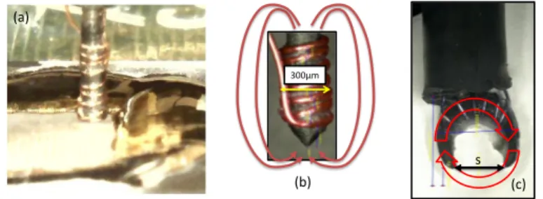
Various EM-injectors can be used according to the context of the analysis. Fig. 2 shows three types of injectors we typically use. All are hand made and designed around a ferrite core to guide the magnetic field lines toward the target. All are also designed in di↵erent sizes. ’Flat’ injectors (see Fig. 2-a) were designed with ferrite diameter ranging between 750µm and 300µm. ’Sharp’ injectors were designed with tip end as small as 50µm (see Fig. 2-b). Finally, ’Crescent’ injectors were designed with an air gap separation ’s’ (see Fig. 2-c) of the ends as small as 450µm.
The ’Flat’ and ’Sharp’ Injectors have been typically designed to localize the magnetic flow below the ferrite tip end. In that case, sharpening the tip-end of the ferrite (see Fig. 2-b), as proposed in [8], allows to further concentrate the flow into a smaller area and thus to expect a higher spatial resolution. Note however that contrarily to what has been obtained by simulation in [8] , practice showed that 4 to 7 turns around the ferrite provide better results than 1 or 2. However, practice also shows that increasing further the number of turns does not help in producing faults and can be counterproductive. Some magnetic field lines can couple with interconnects quite far from the tip end indeed.
(a)
(b) (c)
s
300µm
Fig. 2. EM-Injectors: (a) ’Flat’ Injector (b) ’Sharp’ Injector and (c) ’Crescent’ Injector
If both the ’Flat’ and ’Sharp’ injectors are efficient, they su↵er from a same drawback. The magnetic field lines form close loops from one tip end to the other in an ellipsoid shape as this is roughly represented in the Fig. 2-b by the red arrows. This implies that the resolution can be not so high even if the magnetic field is extremely strong below the tip end of the ’Sharp’ Injectors.
’Crescent’ EM injectors were designed to circumvent this limitation. The idea was to create a circular magnetic field in order to concentrate it between the two ends of the crescent-shaped ferrite. This is expected to avoid (or limit) any magnetic pollution all around the space separating the two ends because the magnetic lines should get out from one end, then surround the top layer of the power / ground network before coming back into the ferrite by the other end. Additionally, because of their geometry, ’crescent’ EM injectors have an interesting property: they are directional. If rotated around the z-axis, the field
lines direction will also rotate of the same angle. This may modify the properties of the coupling between the injector and the target. This is not the case for the ’Flat’ and ’Sharp’ injectors because of their cylindrical geometry.
3
Occurrence of timing faults
Almost all digital ICs are synchronous. Their internal operations are synchro-nized with a common clock signal. Fig. 3 depicts the principle of their inter-nal architecture: blocks of computatiointer-nal logic, to process the data, surrounded by ’launch’ and ’capture’ registers (or DFF, D flip-flop). The data stored in a ’launch’ DFF are released at the logic’s input on a clock rising edge, processed through the logic, then latched into a ’capture’ DFF at the next clock rising edge. The use of synchrony leads to timing constraint requirements (as partially exposed hereafter) which violation may induce computation faults. Thus the au-thors of [3] showed on experimental grounds that EM injection, performed with raw EM injectors, produces timing faults (induced by setup time constraint vi-olations). This observation should explain why a glitch detector was tested and find partially efficient in detecting EM injection in [13]. The setup time con-straint is related to the amount of time spent by the circuit to process a data. This time, roughly speaking, should be lower than the clock period of the target as written more precisely in eq. 1:
TClk > DClk2Q+ DpM ax+ Tsetup+ Tskew+ Tjitter (1)
where TClk is the clock period, DClk2q the delay spent by the ’capturing’ DFF to
launch a new data on its outputs after the clock rising edge (see Fig. 3), Tsetup
the setup time of the DFF capturing one bit of the resulting computation, Tskew
and Tjitter the skew that may exist between the clock signals of ’launch’ and
’capture’ DFFs and its jitter. Finally, DpM axis the biggest propagation delay of
the signal in the computational logic of the device. The time margin that exists between the two hand-sides of eq. 1 is commonly called the timing slack.
D CK Q LOGIC Tskew ‘Launch’ DFF ‘Capture’ DFF CLK D CK Q DpMax
DpM ax depends on many factors. Among them, the most interesting, when
dealing with EM fault injection, are the supply voltage V dd and the processed data. Indeed, EM injection is expected to alter V dd locally and thus to modify
the value of DpM axso that a fault appears by violation of equation 1 (i.e. a setup
time constraint violation). In this instance, EM injection leads to an increase of DpM ax that makes the right side part of eq. 1 bigger than its left
hand-side part (the timing slack became negative). Similarly, when changing the data
processed by the circuit, all terms in eq. 1 remain unchanged except DpM axthat
can change significantly. This change in the DpM ax value from one dataset to
the other thus alters the value Vpulse that must be chosen to produce a fault.
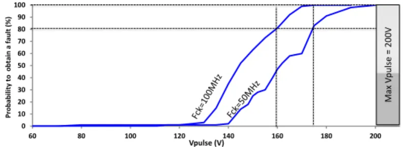
The data dependence of DpM ax is illustrated in Fig. 4. We performed EM
fault injection on an FPGA that embeds an AES hardware module (AES, or advanced encryption standard, is a symmetric encryption algorithm) processing
random texts. EMPs targeted the 9th round of the AES. For any given dataset,
the magnitude Vpulse of the voltage pulse inducing the EM perturbation was
progressively increased from 60 V to 200 V . A first set of experiments was carried out with the FPGA running at a clock frequency of 100 M Hz. The obtained fault
occurrence rate is drawn as a function of Vpulsein Fig. 4. Below⇠ 120 V no fault
was injected. As Vpulse increased further to⇠ 175 V , the fault occurrence rate
grew progressively from 0 % to 100 %. This range corresponds to the appearance
of timing violations. However, depending on DpM ax, which changes with the
currently handled data, the fault probability increases progressively. Beyond a
⇠ 175 V Vpulse, EM fault injection became systematic.
A second set of experiments was performed with the FPGA running at 50 M Hz and also processing the same dataset. We were expecting that this increase of the clock period, which is obviously related to an increase of the
tim-ing slack, would shift the fault occurrence rate towards higher Vpulsemagnitudes.
The obtained fault probability curve at 50 M Hz is depicted in Fig. 4, it exhibits a 15 V shift. Moreover, the induced faults were the same at both 50 M Hz and 100 M Hz for any given dataset. These results are consistent with an EM fault injection mechanism related to timing violations, it is a further experimental reassurance. At that stage, it should be noticed that lowering further the clock frequency (below 20 M Hz) leads to a probability of obtaining a fault stuck at
0 % for Vpulse 2 [ 200V, 200V ] for this positioning of the EM injector. This is
a direct illustration of the limitation associated to EM injection if the latter produces only timing faults. Nevertheless, faults were also observed when the AES was forced to operate at a low clock frequency. This observation suggested us that EM injection does not only produce timing faults.
4
Evidence of a bit-set/bit-reset fault model
In section 3, the occurrence of timing faults was confirmed. This section intends to experimentally demonstrate that EMPs are also able to induce both bit-set and bit-reset faults into the DFFs of an IC. We define a bit-set (resp. bit-reset) fault as forcing to high (resp. low) level the state of a DFF initially at low (resp.
0 10 20 30 40 50 60 70 80 90 100 60 80 100 120 140 160 180 200 Vpulse (V) Pr o b ab ili ty to o b ta in a fa u lt ( %) Ma x V pu lse = 200 V
Fig. 4. Probability to obtain a faulty response from the same AES when operated at a clock frequency equal to 50MHz and 100MHz respectively.
high) level as a result of a disturbance (an EMP injection in our case). To avoid injecting timing faults while performing the experiments reported in this section, the target’s clock was stopped during EMP injection.
4.1 Detecting bit-set and bit-reset faults: test chip and experimental
procedure
Aiming at demonstrating the occurrence of bit-set and bit-reset faults, a specific test chip was designed. Our intend was to be able to easily write and read the content of DFFs to detect, by simple comparison, the occurrence of set or
bit-reset faults. A large FIFO featuring (640⇥ 8) DFFs (64 bytes) was mapped into
a Xilinx spartan 3E-1000 (technology node 90nm). Fig. 5 shows the floorplan of this design. At that point, it should be noticed for the remainder of the paper that all DFFs were mapped with their reset signal active low and their set signal active high.
This test chip was exposed to EMPs for the purpose of drawing a fault sensitivity map. The following and automated procedure was adopted in order to detect (i.e. experimentally demonstrate) the occurrence of bit-set and bit-reset faults:
– 1st step: the EM injector is placed at a given
{X, Y } (initial value {0, 0}) coordinate above the test chip, in its close vicinity (i.e. close to contact) in order to maximize the spatial resolution of the EM injection,
– 2nd step: the content of each byte of the FIFO is set to the hexadecimal
value ’AA’ (’10101010’ in binary),
– 3rd step: the clock signal is stopped in order to avoid the occurrence of a
timing fault,
– 4thstep: an EM pulse, with an amplitude V
pulseranging between -200V and
200V is delivered to the EM injector,
– 5th step: the clock signal is re-activated after a while (several µs) and the
content of the FIFO recovered,
– 6th step: the initial and final contents are compared (a xor operation) in
order to detect the occurrence of bit-set and bit-reset faults, and the result of the comparison is stored in a log file.
– 7th step: steps #2 to #6 are repeated 9 times in order to estimate the
probabilities to obtain bit-set and bit-reset faults at the current position {X, Y },
– 8th step: restart the procedure at step #1 at a new
{X, Y } coordinate in order to obtain a fault sensitivity map of the target.
Row$#1$ Row$#10$ RS232$and$FSM$ 64$x$8$DFF$ 64$x$8$DFF$ package$ IC$core$
Fig. 5. Large chain of registers (FIFO) designed to demonstrate the occurrence of bit-set and bit-reset faults.
4.2 Occurrence of bit-set and bit-reset faults
Many fault sensitivity maps of the target were drawn according to the procedure
described in subsection 4.1 for di↵erent values of Vpulse ranging from -200V to
200V. Di↵erent probes were used. However, we report herein only the results obtained with a ’crescent’ injector characterized by ’s = 450µm’ because these results are the best from a spatial resolution point of view.
During all these experiments, four types of circuit’s behavior were observed: – injection of bit-set faults into a given number of DFFs,
– injection of bit-reset faults into a given number of DFFs, – ’Mute’ or loss of communication with the circuit,
– fault free.
Fig. 6 shows three fault sensitivity maps obtained with a displacement step of the EM injector equal to 300µm (¡ to the air gap of the crescent probe). The whole
die surface (5500µm⇥5000µm) was scanned resulting in 4500µm⇥2400µm fault
to avoid any collision of the injector with bondings. These maps were obtained
with the following settings: Vpulse= +170V and a pulse width P W = 8ns. Fig.
6-a shows the probability to have faults regardless of the type of the obtained faults (either bit-set, bit-reset or Mute). Fig. 6-b reports the probability to have bit-set faults while Fig. 6-c gives the probability to have ’Mutes’. Finally, Fig.6-d shows the orientation of the injector above the IC surface, a parameter that will be discussed later because of the directionality of the injector. Two kind of ’Mutes’ were observed. The first category is characterized by a no response of the IC that does not imply to reprogram the FPGA in order to relaunch the cartography. This suggests the occurrence of a fault in one of the DFF of the finite state machine. The second category was more severe. Indeed relaunching the cartography requires in that case to reprogram the FPGA. This suggests that the bitstream was corrupted by the EM injection.
Probability to obtain faults
4500µm 2 4 0 0 µm Probability 0 1
Probability to obtain bitsets
2 4 0 0 µm 4500µm 4500µm 240 0µm
Probability to obtain ‘Mutes’
(a)
(b) (c)
(d)
Probe Orientation
Fig. 6. Probabilities to produce (a) faults regardless of the fault type (b) bit-set faults (c) ’mutes’ and (d) injector orientation (air gap along the y-axis) – (170V, 8ns) EMP.
Obtaining these sensitivity maps, especially the one of Fig. 6-b, constitutes an experimental demonstration that EM injection, conducted with enhanced injec-tors, is able to produce bit-set faults. This was our first objective. Additionally, one may observe once again that EM injection is local and reproducible. Indeed, we did verify that the bit-set faults obtained, at a given coordinate from one injection to another, were exactly the same.
4.3 Correlation between the EMP polarity and the occurrence of
bit-set and bit-reset faults.
Despite being a proof that EMP injection may inject faults into registers which are not related to timing violations, the experiments reported in subsection 4.2 never leaded to a bit-reset fault. Considering that the set signal of the DFFs was
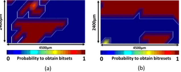
active high and that their reset signal active low, a similar set of experiments was
relaunched for both achievable polarities of the EMPs: with Vpulse= 140V and
+140V instead of +170V only. The idea that motivated this experiment was the assumption that a pulse of a given polarity may a↵ect more the ground network than the power network (or vice-versa). Therefore, it may be easier to induce bit-set than bit-reset faults (or the contrary) depending on the EMP polarity. Note however that the polarity is here an arbitrary notion that depends in our case of both the injector orientation and the sign of the voltage spike. For the sake of simplicity, we choose here to define the polarity as positive when the pulse a↵ects more the ’set’ signal which is active high than the ’reset’ signal which is active low.
4500µm 0 1 4500µm 24 00 µm 240 0µm 0 1
Probability to obtain bitsets Probability to obtain bitresets
(a) (b)
Fig. 7. Probabilities to obtain (a) bit-set faults with Vpulse= +140V and (b) bit-reset
faults with Vpulse= 140V
Fig. 7-a gives the probability to obtain bit-set faults when applying a positive pulse of amplitude +140V instead of +170V for Fig. 6-b. Comparing these two
figures (Fig. 6-b and 7-a) allows observing that reducing Vpulse reduces the size
of the fault sensitive areas. Note however, that the two maps remain similar in
shape. This indicates that the magnitude Vpulseis an efficient control parameter
for EM injection, as it was expected.
Fig. 7-b gives the probability to obtain bit-reset faults when applying a
neg-ative pulse of amplitude 140V ; during this set of experiments not any bit-set
fault was induced. One may observed that the two cartographies are completely di↵erent indicating that the susceptibility of an IC to a positive or a negative pulse may be radically di↵erent.
Nevertheless, the main conclusion that can be drawn from these experiments is that the pulse polarity (and therefore the injector orientation) is a key factor in controlling the type of EMP-induced faults. It seems to allow targeting more the ground network than the power network according to the topology of the IC. These results also suggest that according to their occurrence, bit-set and bit-reset faults are related to the way DFF are designed (set / reset signals active low or high). However, further investigations are mandatory to sustain this assumption.
4.4 Threshold voltage for the occurrence of bit-set faults
The evolution with Vpulse of the probability to obtain timing faults has been
experimentally estimated in section 3. According to [4], this evolution should be smooth when random plaintexts are passed to the AES because the electri-cal paths and therefore the minimum timing slack changes with the processed plaintexts. This has been verified in section 3. Indeed, this evolution has been found, for the AES mapped into the FPGA and the considered positioning of
the injector, varying from 10% to 90% for Vpulse ranging from 130V to 180V
when the AES operates at 100 M Hz.
Pr ob abil ity t o obse rv e b itsets Vd d = 1.10V V dd = 1.15 V Vd d = 1.20V Vd d = 1.25V Vd d = 1.30V Vpulse (V)
Fig. 8. Evolutions of the probabilities to obtain bit-set faults when the FPGA is sup-plied with di↵erent V dd values.
The evolution with Vpulse of the probability to obtain bit-set faults has also
been measured at several {X, Y } coordinates for di↵erent values of the supply
voltage, V dd, of the FPGA. Fig. 8 shows the result obtained for one positioning of the injector but for di↵erent Vdd values. As depicted, for this positioning, as well as for many other that have been tested, the evolution is really sharp. The
probabilities vary from 10% to 90% when the the magnitude of Vpulsevaries from
less than 1V, which is the voltage resolution of our pulse generator. This confirms the crossing of a threshold, Vpulseth , above which the probability to obtain a bit-set
(or a bit-reset) is equal to 1. Additionally, this threshold voltage slowly varies with the supply voltage of the FPGA. It should also be noticed that from one
positioning of the EM injector to another one, Vpulseth,bit set can vary for several
tens or even move out of the voltage range of our pulse generator (-200V to +200V).
4200µm 24 00 µm 4200µm 24 00 µm
Probability to obtain bitreset
0 1
Fig. 9. Evolutions of the Probabilities to obtain bit-set faults with Vpulse when the
EM injector is parallel or orthogonal to the X-axis
4.5 EM injector orientation
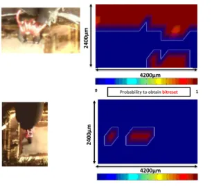
In section 2, it is mentioned that ’crescent’ injectors, because of their geometry, produce a polarized magnetic field, i.e. are directional. This characteristic of these enhanced EM injectors was experimentally verified. Two fault sensitivity
maps were drawn (Vpulse = 140V ) with the EM-injector positioned parallel
and perpendicular to the X-axis as illustrated in Fig. 9 which also discloses the obtained maps. It is obvious that the susceptibility of the IC to magnetic fields parallel and perpendicular to the X-axis is di↵erent. This could may be be explained by the way the top metal layers of the power (V dd) and ground (Gnd) networks are routed. It is common practice to route perpendicular to each other the V dd and Gnd metal lines. However, we didn’t have this information for the FPGA under consideration. Nevertheless, this result confirms that ’crescent’ injector are, as expected, directional.
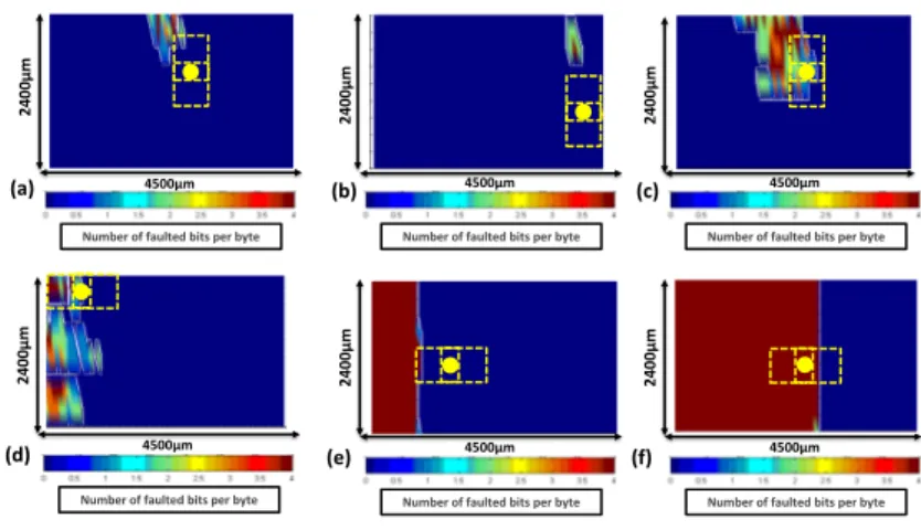
4.6 Fault types and spatial resolution
Considering the legacy from laser injection techniques, one may wonder what is the spatial resolution of EM fault injection, but also the types of faults it produces. The experimental faults maps were further analyzed: Fig 10 reports some results illustrating what was observed. More precisely each sub-figure gives the number of faulted bits per byte for all bytes, for given position and orientation of the injector (shown by the large dot and the dotted rectangles) and given polarity and amplitude of the pulse (given in the caption). It is therefore possible to observe, for several settings of the EM injection, the spatial resolution of the
Number of faulted bits per byte 4500µm 24 00 µm 4500µm 24 00 µm
Number of faulted bits per byte
4500µm
24
00
µm
Number of faulted bits per byte
Number of faulted bits per byte
4500µm 24 00 µm (a) (b) (d) (e) 4500µm 24 00 µm
Number of faulted bits per byte
Number of faulted bits per byte
4500µm 24 00 µm (c) (f)
Fig. 10. Fault types and illustration of EM injection e↵ects for four di↵erent settings of injection parameters: (a) Vpulse = 100V , perpendicular; (b) Vpulse = 100V ,
perpendicular; (c) Vpulse = 140V , perpendicular; (d) 110V, parallel ; (e) -110V,
parallel; (f) Vpulse= 110V , parallel.
EM injection and the type of induced faults. Fig. 10a and b (resp. e and -f) show the e↵ect of the positioning of the injector; all others settings being constant. These sub-figures highlight that EM injection can be very local. Fig.
10-a 10-and -c 10-allow to observe the e↵ect of Vpulse. Fig. 10-a,-b,-c should be compared
to Fig. 10 -d,-e and -f to observe the impact of the injector orientation. Fig. 10 -d should be compared to -e or -f to observe the e↵ect of polarity.
These six maps allow to observe that both the area a↵ected (let’s denote it by spatial resolution even if it is not the most appropriated term) by the EM injection and the types of induced faults (from single bit to multi-bits and from single byte to multi bytes that were all observed during our experiments) strongly depend on several parameters: the pulse amplitude and its polarity, the injector position and its orientation. It was also observed (not illustrated herein) that the distance d (d= 0 to d=1.5mm in our experiments) separating the injector from the IC surface changes significantly the obtained results. Nevertheless, even if the size of the area a↵ected by the EM injection significantly varies with the aforementioned parameters, one may observe the e↵ect is not global but more or less local according to the settings of the injection.
These observations could be explained by the mechanism exploited by EM injection : a local EM coupling between an emitting antenna and one or several receiving antennas. This implies that the spatial resolution and the e↵ects pro-duced by EM injection depend of course on the characteristics the EM injector (emitting antenna) but also on the characteristics of the receiving antennas, i.e. on the way the supply network of the IC is designed. It is therefore extremely difficult to define the spatial resolution of an EM injection, or to give any figure. It depends on both the Device Under Test and the settings of the injection. One
may only characterize the spatial resolution of its injector in free space; but this is of reduced interest for the practice of EM injection.
As a result, let us conclude that there are several parameters (additional parameters with respect to laser injection) allowing to select the area a↵ected by the EM injection and the faults that are produced. The EM injection can thus be perceived as more complex than laser injection in this regard. However, EM injection o↵ers more degrees of freedom (more tuning parameters), to obtain the desired faults. However, their induction remain conditioned by the presence of the appropriated receiving antenna(s) in the IC. Experiments revealed there are plenty. One has just to target the right ones with an efficient EM injector, i.e. with the EM injector having the best spatial resolution in the empty space. At the moment, no general recipe emerges to quickly and directly find the rights settings for a given desired e↵ect. Experimentation still prevails.
5
Discussion
At that stage, it has been experimentally observed that EM injection can produce timing faults. This result was expected from [4]. It has also been verified that
the minimum pulse amplitude, Vpulseth,timing, to produce, with a high probability
(> 0.8), a timing fault depends on the plaintext processed by the AES: it could vary for one or four tens of volts from one plaintext to the other.
Additionally to these results, we experimentally demonstrated that EM in-jection, conducted with enhanced EM injectors, can produce bit-set and bit-reset faults in more or less local manner according to the settings of the EM injection. It was also observed that the minimum pulse amplitudes related to the injection of bit-sets or bit-resets with a probability higher than 0.8 can vary for several tens of volts from one positioning of the EM injector to another one.
All these considerations suggest that it is particularly difficult to decide if a fault induced by an EMP is a timing fault, a bit-set or a bit-reset. It is even pos-sible that all type of faults coexist during a same EM injection. Nevertheless, the experimental demonstration that EM injection can produce bit-set or bit-reset faults significantly enlarges the scope of what can be done with EM injection.
6
Conclusion
In this paper, we have experimentally demonstrated that EM injection, con-ducted with enhanced EM injectors, is able to produce bit-set and bit-reset faults in addition to timing faults. This experimental demonstration significantly en-larges the scope of what can be done with EM injection, i.e. the EM fault model. Indeed, if this was not the case, EM injection would have been of reduced inter-est for the evaluation of IC designed with modern technologies but operating at reduced clock frequency, such as smartcards.
Such a result was obtained thanks to the design of EM injectors according to a simple idea : concentrating the magnetic field on the smallest possible area at
constant power rather than increasing the power delivered to the EM injector. It should be noticed that there is still room to enhance EM injectors.
References
1. Pierre Bayon, Lilian Bossuet, Alain Aubert, Viktor Fischer, Fran¸cois Poucheret, Bruno Robisson, and Philippe Maurine. Contactless electromagnetic active attack on ring oscillator based true random number generator. In COSADE, pages 151– 166, 2012.
2. Dan Boneh, Richard A. DeMillo, and Richard J. Lipton. On the importance of checking cryptographic protocols for faults (extended abstract). In EUROCRYPT, pages 37–51, 1997.
3. Amine Dehbaoui, Jean-Max Dutertre, Bruno Robisson, P. Orsatelli, Philippe Maurine, and Assia Tria. Injection of transient faults using electromagnetic pulses -practical results on a cryptographic system-. IACR Cryptology ePrint Archive, 2012:123, 2012.
4. Amine Dehbaoui, Jean-Max Dutertre, Bruno Robisson, and Assia Tria. Electro-magnetic transient faults injection on a hardware and a software implementations of aes. In FDTC, pages 7–15, 2012.
5. Karine Gandolfi, Karine G, Christophe Mourtel, and Franncis Olivier. Electro-magnetic analysis: Concrete results, 2001.
6. Paul C. Kocher. Timing attacks on implementations of diffie-hellman, rsa, dss, and other systems. In CRYPTO ’96: Proceedings of the 16th Annual International Cryptology Conference on Advances in Cryptology, pages 104–113, London, UK, 1996. Springer-Verlag.
7. Philippe Maurine. Techniques for em fault injection: Equipments and experimental results. In FDTC, pages 3–4, 2012.
8. R. Omarouayache, J. Raoult, S. Jarrix, L. Chusseau, and P. Maurine. Magnetic microprobe design for em fault attackmagnetic microprobe design for em fault attack. In emceurope, 2013.
9. Fran¸cois Poucheret, Karim Tobich, Mathieu Lisart, Laurent Chusseau, Bruno Ro-bisson, and Philippe Maurine. Local and direct em injection of power into cmos integrated circuits. In FDTC, pages 100–104, 2011.
10. J¨orn-Marc Schmidt and Michael Hutter. Optical and em fault-attacks on crt-based rsa: Concrete results. In Johannes Wolkerstorfer Karl C. Posch, editor, Austrochip 2007, 15th Austrian Workhop on Microelectronics, 11 October 2007, Graz, Austria, Proceedings, pages 61 – 67. Verlag der Technischen Universit¨at Graz, 2007. 11. Sergei P. Skorobogatov and Ross J. Anderson. Optical fault induction attacks.
pages 2–12. Springer-Verlag, 2002.
12. Karim Tobich, Philippe Maurine, Pierre-Yvan Liardet, Mathieu Lisart, and Thomas Ordas. Voltage spikes on the substrate to obtain timing faults. In DSD, pages 483–486, 2013.
13. Loic Zussa, Amine Dehbaoui, Karim Tobich, Jean-Max Dutertre, Philippe Mau-rine, Ludovic Guillaume-Sage, Jessy Cl´edi`ere, and Assia Tria. Efficiency of a glitch detector against electromagnetic fault injection. In DATE, pages 1–6, 2014.