Hans Scheffel Paul Stolzmann Markus J. Wilhelm Mario Lachat Lotus Desbiolles Sebastian Leschka Thomas Frauenfelder Thomas Schertler Borut Marincek Hatem Alkadhi Received: 18 November 2008 Revised: 19 January 2009 Accepted: 22 February 2009 Published online: 1 May 2009
# European Society of Radiology 2009
Conventional radiography and computed
tomography of cardiac assist devices
Abstract Patients intended for circu-latory support by cardiac assist devices (CAD) usually suffer from end-stage acute or chronic heart failure. Since the introduction of CAD in 1963 by DeBakey and coworkers, the systems have gone through a substantial evolution and have been increasingly used in the intervening decades. The spectrum of CAD includes a variety of systems serving to assist the systolic function of the left ventricle, the right ventricle, or both. Conventional radiography and multi-slice spiral computed tomography (CT) are the most commonly used radiological techniques for imaging patients with a CAD. CT is very useful for evaluating CAD systems by using both two- and three-dimensional re-constructions of the volumetric data
sets. The two techniques together allow for the comprehensive assess-ment of patients with devices by imaging the in- and outflow cannulae, the anastomoses, the position of the pump, as well as associated compli-cations. A close collaboration with cardiac surgeons with expertise in the field of circulatory support is deemed necessary for adequate image inter-pretation. This article describes the technical diversity of the currently available CAD systems. The imaging characteristics on conventional radi-ography and multislice spiral CT as well as the typical complications of their use are demonstrated.
Keywords Cardiac assist device . Conventional radiography .
Computed tomography . Heart failure
Introduction
Heart failure, the final common pathway of myocardial dysfunction in most forms of cardiac disease, is one of the leading causes of death in developed countries [1]. The incidence of heart failure has increased by a factor of five in the past three decades [2]. Most advanced pharmacological and surgical treatments fail in some patients, and for the most severe forms of cardiac dysfunction leading to irreversible biventricular end-stage heart failure, cardiac transplantation has emerged as the only effective therapy, affording longevity and quality of life [3]. Implantation of a totally artificial heart is another option, but requires complete removal of the native heart [4]. An alternative technique was introduced by DeBakey and coworkers [5], who were the first to develop a cardiac assist device
(CAD). A CAD operates as a mechanical circulatory support system that assists the native heart without needing its removal [6]. The first application of a CAD was performed in 1963 in a patient with a postoperative cardiogenic shock. After CAD implantation, improvement in the patient’s cardiac function developed after 1 week of support and the device could be finally removed [5]. In 1971 [7], DeBakey reviewed his experience with this technology and outlined the lack of a portable control mechanism and power source as being one of the main barriers to its wider use. This is understandable because the first CAD systems were completely or partially paracorporeal and electrically motor driven. This required a cable (drive line) for the energy supply and for device control that was located in a small trolley pulled by the patient [8]. Since their introduction, CAD systems have undergone a substantial evolution, H. Scheffel . P. Stolzmann .
L. Desbiolles . S. Leschka . T. Frauenfelder . T. Schertler . B. Marincek . H. Alkadhi (*) Institute of Diagnostic Radiology, University Hospital Zurich, Raemistrasse 100, 8091 Zurich, Switzerland e-mail: [email protected] Tel.: +41-44-2551111 Fax: +41-44-2554443 M. J. Wilhelm . M. Lachat Clinic for Cardiovascular Surgery, University Hospital Zurich, Zurich, Switzerland
including the development of intracorporeal implants with percutaneous energy transmission by a small battery connected with the patient’s belt [9].
Circulatory support systems are able to act as a left ventricular assist device (LVAD) supporting the left ventricle, as a right ventricular assist device (RVAD) supporting the right ventricle, or as a biventricular assist device (BVAD) supporting both ventricles [10]. Patients receive mechanical circulatory support by implantation of a CAD system for one of the three following intentions: (a) as a bridge-to-transplant that provides circulatory assis-tance for the patient awaiting heart transplant; (b) as a bridge-to-recovery that provides circulatory assistance allowing the heart to recover (mostly from postcardiotomy cardiogenic shock or myocarditis); or (c) as a long-term and permanent circulatory assistance, being an alternative to heart transplantation (so-called destination therapy) [11]. The last indication was documented to be a promising alternative to heart transplantation in adults [11,12].
Because of the increasing use of CAD systems, radiologists are confronted more and more often with such devices in their daily clinical practice. Therefore, radiologists need to be familiar with the typical imaging features of the various CAD systems on conventional radiography and multislice computed tomography (CT), the two most frequently used radiological techniques for imaging these patients, in order to substantiate their role as cardiovascular specialists [13].
Types of cardiac assist devices
A CAD usually consists of an inflow cannula containing blood from the ventricle that is assisted by the device. The inflow cannula connects the assisted ventricle to the pump where the blood is powered forward into the outflow cannula. The outflow cannula is a connection between the pumping element of the CAD and the corresponding great vessel of the assisted ventricle. The path of the blood flow can be schematically simplified as follows:
LVAD: left ventricle → inflow cannula → pumping element→ outflow cannula → ascending aorta RVAD: right ventricle→ inflow cannula → pumping element→ outflow cannula → pulmonary trunk
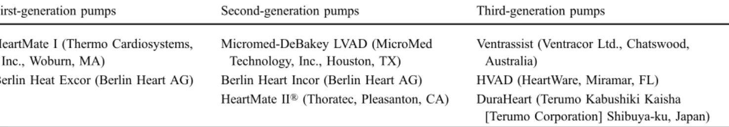
Currently, there are a wide variety of CAD systems offered by different vendors (Table1). Early CAD systems were extensions of the heart–lung machine, which could drain the blood in a nonpulsatile manner from the heart via peripheral vascular access to oxygenate the blood extra-corporeally and return it again to the patient, also called extracorporeal membrane oxygenation (ECMO) [14]. The patient was maintained on mechanical ventilation and was sedated, which limited the use of such systems to resuscitation after either cardiac arrest or profound shock [14]. Recent developments have led to devices with pulsatile blood flow corresponding to the physiology of the native heart, whereas the latest evolved systems again show a nonpulsatile axial or centrifugal flow, delivering continuous blood flow with the advantage of size and weight reduction and smaller energy demands [15]. The currently available CAD systems can be categorised into three generations reflecting the order in which they were developed and the type of pumping mechanism used [16] (Table1).
First-generation pumps Development in the early 1980s led to CAD systems being smaller than early pumps used for ECMO. These pumps could generate pulsatile blood flow through pneumatic or air technology compressing a reservoir of blood drained from the ventricle. The size of these devices restricted their use to patients with an adequate size defined by body surface area to ensure device location [17]. This type of device can provide support to the right ventricle, the left ventricle or to both ventricles. An example is the Berlin Heat Excor (Berlin Heart AG, Berlin, Germany), a paracorporeal and pneumatically accentuated pulsatile blood pump, being one of the first devices designed for the use as a LVAD, RVAD or BVAD (Fig. 1a). The pneumatic drive line connects the device to an external portable console. The paracorporeal external pneumatic pump driver is portable and allows mobility and ambulant care of the patient.
First-generation pulsatile CAD systems have several disadvantages, such as their large size and complexity (e.g. they contain many moving parts, including valves), which can affect the device’s durability [18]. A study has shown that pulsatile flow was not able to maintain the integrity of the pulmonary or systemic circulation as well as the organ function, whereas other experiments have suggested
Table 1 Overview of the various cardiac assist devices provided by different vendors
First-generation pumps Second-generation pumps Third-generation pumps HeartMate I (Thermo Cardiosystems,
Inc., Woburn, MA)
Micromed-DeBakey LVAD (MicroMed Technology, Inc., Houston, TX)
Ventrassist (Ventracor Ltd., Chatswood, Australia)
Berlin Heat Excor (Berlin Heart AG) Berlin Heart Incor (Berlin Heart AG) HVAD (HeartWare, Miramar, FL) HeartMate II® (Thoratec, Pleasanton, CA) DuraHeart (Terumo Kabushiki Kaisha
evidence to the contrary [19]. However, these devices are still in broad use in many centres because of their versatility, especially in supporting the right ventricle [8]. An advance in the field of pulsatile devices was the development of implantable pumps. These devices can be implanted either preperitoneally or intraperitoneally, with the inflow to the pump via the left ventricular apex only, and the outflow graft to the ascending aorta [14]. One of these devices is the HeartMate® I (Thermo Cardiosystems, Inc., Woburn, MA, USA) (Table 1).
Second-generation pumps Second-generation CAD sys-tems are axial-flow pumps with continuous blood flow. They are considerably smaller and safer because of only one moving part, which is the rotor generating the blood
flow. These systems are expected to have a greater durability than first-generation devices. Experience with these devices, e.g. Micromed-DeBakey LVAD (MicroMed Technology, Inc., Houston, TX), HeartMate II® (Thoratec, Pleasanton, CA) and Berlin Heart INCOR (Berlin Heart AG, Berlin, Germany), is increasing [20, 21] (Table 1). The Berlin Heart Incor (Berlin Heart AG) (Fig.3a) weighs 200 g and is one of the latest developments in the field of CAD systems designed to work as an LVAD. Remarkably, the continuous blood flow and relative lack of pulsatility appears to be well tolerated, but longer periods of follow-up are required to confirm this finding [16]. The Micromed-DeBakey (MicroMed Technology, Inc., Hous-ton, TX) is an implantable axial-flow, nonpulsatile pump with a weight below 100 g (Fig. 4a).
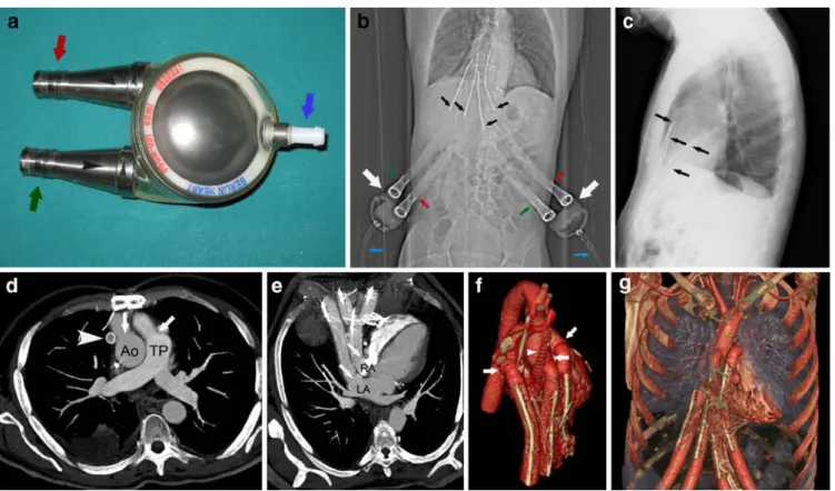
Fig. 1 A 51-year-old male patient who underwent surgery for a Berlin Heart Excor intended to work as a BVAD for bridge-to-transplant. a Photograph of the Berlin Heart Excor, ex vivo. The device has two connections for the inflow (green arrow) and outflow (red arrow) cannulae. Additionally, the adapter for the pneumatic drive line (blue arrow) is visible. One Berlin Heart Excor, such as illustrated, supports one ventricle. b The CT depicts the two extracorporeally located Berlin Heart Excor pumps (white arrows) and the inflow (green arrows) and outflow (red arrows) cannulae. Note the pneumatic drive line (blue arrows). The four cannulae positions can be inferred from their radiopaque stabilising wires (black arrows). c Chest radiography in a lateral projection depicting the radiopaque stabilising wires (arrows) entering the thoracic cavity through the upper abdominal wall. d Axial thin-slab maximum intensity projection of the computed tomography data set at the level of the ascending aorta (Ao) and pulmonary trunk (TP) demonstrating
intact anastomoses of the outflow cannulae (arrows) connecting the Berlin Heart Excor with the aorta and the pulmonary trunk. Note the additional Gore-Tex graft connecting the innominate vein to the right atrium (arrowhead) in this patient. e Oblique axial thin-slab maximum intensity projection of the computed tomography data set at the level of the left (LA) and right (RA) atrium, demonstrating the intact positions of the inflow cannulae (arrows) connecting the CAD to both atria. f Three-dimensional volume rendered computed tomography image in an anterior view provides an overview regarding the complex postsurgical anatomy of the native heart and illustrates the cannulae with their anastomoses (arrows) and the Gore-Tex graft connecting the innominate vein to the right atrium (arrowhead). g Three-dimensional volume rendered computed tomography image in an anterior view illustrates the course of the in- and outflow cannulae entering the thoracic cavity via the upper abdominal wall
Third-generation pumps One of the most promising inventions in CAD technology was the development of centrifugal pumps. These devices are smaller in size compared with pulsatile CAD systems with simplification of their implantation that extends their application to children and small adults [22, 23]. Centrifugal pumps generate continuous, nonphasic blood flow. The current third-generation pumps are thought to last approximately 5 years and their performance is currently being evaluated in several phase I studies involving the Ventrassist® (Ventracor Ltd., Chatswood, Australia) and HVAD® (HeartWare, Miramar, FL) devices, and more recently the DuraHeart® (Terumo Kabushiki Kaisha [Terumo Corporation] Shibuya-ku, Japan) system [16] (Table1).
Patient selection
The selection of the CAD depends on the type of heart failure and on the overall severity of the heart disease representing the most important factors in the outcome of patients with CAD [24]. Similar to heart transplantation, the indication for placement of a CAD is an end-stage heart failure that is refractory to maximum medical drug therapy and without consideration of conventional heart surgery or other catheter techniques (e.g. cardiac valvular disease or arrhythmia). It is important to mention that CAD surgery is only the second choice in the absence of an available donor heart because some patients will qualify for CAD but not for heart transplantation. For example, patients with contraindications for immunosuppression, of age higher than 65 years, severe peripheral vascular disease, and severe pulmonary emphysema are precluded from heart transplantation, but may be candidates for CAD [11].
Patients
Between 1999 and 2007, 43 patients underwent surgery for a CAD at the Clinic for Cardiovascular Surgery of our hospital. Of these 43 patients, 13 (2 women, 11 men; mean age 46.2±9.9 years, range 18–54 years) with an extra- or intracorporeal CAD underwent conventional radiography and CT at our institute. The 13 patients suffered from end-stage acute (n=4) or chronic (n=9) heart failure before surgery (Table 2). Preoperative underlying heart disease was cardiomyopathy in 12 patients (4 ischaemic, 5 dilatative, 1 idiopathic, 1 following surgery for congenital transposition of the great arteries in childhood, and 1 restrictive cardiomyopathy due to myocardial amyloido-sis). All the patients in this group (n=12) were awaiting a cardiac transplant and received a CAD intended for bridge-to-transplant. One patient underwent surgery for a CAD intended for bridge-to-recovery following heart transplan-tation. CT is not routinely performed in patients after CAD implantation, but only in those in whom complications are
suspected. All these 13 patients underwent a chest CT, 4 of whom had an additional abdominal CT. The reasons for referral to chest CT were suspected pneumonia, device thrombosis or malpositioning, pseudoaneurysm formation at the anastomosis site, embolism, haematoma or dissection (Table2).
CT protocol
All CT examinations were performed using multislice spiral CT systems (Table3). In five patients a 4-slice CT system was used (Volume Zoom, Siemens Medical Solutions, Forchheim, Germany), in three patients a 16-slice CT system (Sensation 16, Siemens), and in five Table 2 Patients’ demographic data, types of assist devices, indications for device implantation and causes of referral to computed tomography
Patients 13
Mean age ± SD (years) 46.2±9.9
Gender
Male 11
Female 2
Indication for CAD
Dilatative cardiomyopathy 5
Ischaemic cardiomyopathy 4
Idiopathic cardiomyopathy 1
Restrictive cardiomyopathy 1
Congenital heart disease 1
Dysplastic right ventricular cardiomyopathic 1 Arrhythmia and heart transplantation
Intention for CAD
Bridge-to-transplant 12
Bridge-to-recovery 1
Type of CAD
Micromed-DeBakey LVAD 6
Berlin Heart Incor 5
Berlin Heart Excor BVAD 1
Berlin Heart Excor RVAD 1
Causes of referral to CT
Infection 6
Device malpositioning 4
Pseudoaneurysm at anastomosis site 4
Pneumonia 4
Embolism 3
Thrombosis 3
Aortic dissection 1
Haematoma 1
SD standard deviation, CAD cardiac assist device, LVAD left ventricular assist device, RVAD right ventricular assist device, BVAD biventricular assist device, CT computed tomography
patients a 64-slice CT system (Sensation 64, Siemens). We acquired unenhanced images as well as imaging in arterial and venous phases after intravenous administration of non-ionic, iodinated contrast media (Ultravist 300, 300 mg/ml, Bayer Schering Pharma, Berlin, Germany). The beginning of
the arterial phase was controlled by bolus tracking after placing a region of interest (ROI) in the proximal descending aorta. With the 4-slice CT system, image acquisition started after the predefined threshold of 100 Hounsfield units (HU) was reached; with the 16- and 64-slice CT systems the threshold was set to 140 HU. The venous phase was performed 80 s after initiation of contrast medium injection. All images were reconstructed using a soft-medium tissue kernel (B30f) and a hard-sharp bone kernel (B50f). Parameters are detailed in Table3.
Imaging findings
For the evaluation of the CAD systems, various postpro-cessing techniques of the CT data sets were used. These included multiplanar reformations (MPR), maximum in-tensity projections (MIP) and volume rendering (VR). Postprocessing in our patients was performed on an external workstation (Multimodality Workplace, Siemens) Table 3 CT parameters for the arterial and the venous phase of contrast enhancement
Systemsa Arterial phase Venous phase
Slice thickness/ increment
kV/mAsa Collimation CM amount/
delay
Slice thickness/ increment
kV/mAsa Collimation CM amount/
delay 4-detector row CT (n=5) 2.0/1.0 120/180 4×1.0 160/bolus tracking 3.0/2.0 120/180 4×1.0 160/80 s 16-detector row CT (n=3) 1.5/1.0 120/180 16×0.75 140/bolus tracking 2.0/1.0 120/180 16×0.75 140/80 s 64-slice CT (n=5) 1.0/0.8 120/180 64×0.6b 140/bolus tracking 2.0/1.5 120/180 64×0.6b 140/80 s kV kilo voltage, mAs tube current–time product, CM contrast media
a
Automated tube current modulation was routinely used in all patients
bZ-flying spot
3Fig. 2 A 61-year-old male patient who underwent surgery for a Berlin Heart Excor RVAD as a bridge-to-recovery. a The CT depicts the Berlin Heart Excor pump that is located extracorporeally (white arrow), as well as the inflow (green arrow) and outflow cannulae (red arrow). The pneumatic drive line of the CAD is also shown (blue arrow). The radiopaque stabilising wires delineate the in- and outflow cannulae in their course through the upper abdominal wall into the thoracic cavity. Note bilateral pacemaker devices (arrow-heads) and electrodes. b Axial computed tomography image demonstrates intact anastomosis (arrow) connecting the outflow cannula to the pulmonary trunk (TP). c Axial computed tomography reconstruction at the level of the right atrium (RA) demonstrates an intact position of the inflow cannula at the right atrium (arrow). d Three-dimensional volume rendered computed tomography image in a left anterior oblique view provides an overview of the heart including the right (RV) and left (LV) ventricle, as well as the outflow cannula (arrow) connected to the pulmonary trunk (TP). e Three-dimensional volume rendered computed tomography image in a left posterior oblique demonstrates the inflow cannula (arrow) connected to the right atrium (RA). The left atrium (RA) and the superior vena cava (SVC) are also shown
equipped with postprocessing software (Syngo InSpace4D, Siemens).
Berlin Heart Excor
In the patients with a Berlin Heart Excor, conventional radiography (both chest radiography and CT scanogram) allowed for the delineation of the wire-directed in- and outflow cannulae that were placed depending on the type of assistance (BVAD or RVAD, Figs. 1b, c and 2a). The cannulae exit the upper abdominal wall and are connected
to the paracorporeally placed blood pump. The pneumatic drive line could be visualised in all patients. Use of postprocessed images with CT allowed for the accurate depiction of the CAD and the native anatomy of the heart and adjacent soft tissue structures, lung and osseous thoracic cage. In the patient with a Berlin Heart Excor BVAD, the outflow cannula in the pulmonary artery and ascending aorta as well as the inflow cannula in the right and left atrium could be clearly visualised (Fig.1d, e). In the patient with a Berlin Heart Excor RVAD, the inflow cannula connected to the right atrium and the outflow cannula connected to the pulmonary artery could be Fig. 3 A 58-year old male patient with a Berlin Heart Incor LVAD
as a bridge-to-transplant. a Photograph of a Berlin Heart Incor LVAD, ex vivo, designed for use as an LVAD. The connections for the inflow (green arrow) and the outflow (red arrow) cannulae are depicted; access for the drive line for control and energy supply of the pump is also visible (orange arrow). b Chest radiography in a posteroanterior projection shows the inflow (green arrow) and outflow (red arrow) cannulae as well as the pump (thick black arrow), which is located intrapericardially. The radiopaque inflow cannula to the left ventricle (thin black arrow) and the spring lock of the outflow cannula (double arrow) are also depicted. The drive line for control and energy supply of the pump exits through the left upper abdominal wall (orange arrow). In this patient, the left upper abdominal quadrant was chosen for the drive line exit, as the right upper abdominal quadrant, which is usually used, was occupied by an artificial bowel stoma. Note the small loculated pleural effusion in the horizontal fissure (arrowhead). c Chest radiography in a lateral projection depicts the radiopaque Berlin Heart Incor device located in the pericardial cavity (thick black arrow), the inflow cannula of the left ventricle (green arrow), the energy supply cable (orange arrow) and the spring lock of the outflow cannula (double
arrow). Note the mechanical mitral valve prosthesis (arrowhead). d Oblique sagittal computed tomography reconstruction at the level of the ascending aorta (Ao) demonstrates intact anastomoses (thick white arrow) of the outflow cannula connecting the pump to the ascending aorta. Note the spring lock (black arrow) at the outflow cannula and the severe metallic artefacts (thin white arrows) evoked by the Berlin Heart Incor (not shown). e Oblique coronal computed tomography reconstruction at the level of the left ventricular apex demonstrates the Berlin Heart Incor with the connections of the inflow (white arrow) and outflow (black arrow) cannulae. f Oblique axial computed tomography reconstruction at the level of the ascending aorta (Ao) and the left ventricle (LV) demonstrate intact anastomoses of the cannulae connecting the pump to the apex of the heart (black arrow) and the ascending aorta (white arrow). g Three-dimensional volume rendered computed tomography image in an anterior view illustrating the course and positions of the in- and outflow cannulae, the Berlin Heart Incor (double arrow) and the native heart with the right (RV) and left (LV) ventricle. The anastomoses are connecting the pump to the apex of the heart (arrowhead) and the ascending aorta (arrow)
accurately depicted (Fig. 2b, c). The course of the in- and outflow cannulae exiting the upper abdominal wall as well as the connection to the pumps were demonstrated by CT using the VR technique (Figs.1f, g and2d, e).
Berlin Heart Incor
The intracorporeal position of the Berlin Heart Incor could be demonstrated by conventional radiography (Fig.3b, c) in two projections as well as the in- and outflow cannulae that were placed in the left ventricle and ascending aorta. CT showed the inflow conduit that was placed in the left ventricular apex, and the outflow conduit that was sutured onto the ascending aorta (Fig.3d–f). The implantable pump housing was placed inside the pericardial cavity and the drive line exited the abdominal wall through the right upper quadrant. The connection to the pumps could be depicted by using VR images (Fig.3g).
Micromed-DeBakey
Both the device and the cannulae positions of the Micromed-DeBakey LAVD were depicted by conventional radiography (Fig.4b, c). In the patients with a Micromed-DeBakey LVAD, the inflow cannula was placed in the left ventricular apex and the outflow graft was sutured onto the ascending or descending aorta which can be demonstrated by CT (Fig. 4d–f). The blood pump was placed in the pericardium with little extension into the abdominal wall, and the drive line exited the skin through the right upper abdominal quadrant.
Analysis of image techniques
MPR of CT data generate images of structures that follow an oblique course to the axial plane. This is particularly useful for the illustration of in- and outflow cannulae of the Fig. 4 A 54-year-old patient who underwent surgery for an
intracorporeally placed Micromed-DeBakey LVAD as a bridge-to-transplant. a Photograph of the Micromed-DeBakey LVAD, ex vivo. The connections for the inflow cannula (green arrow) and the outflow graft (red arrow), as well as the pumping element (double arrow) and the drive line for control and energy supply (orange arrow), are depicted. The flow sensor of the Micromed-DeBakey LVAD is also shown (arrowhead). b Chest radiography in a posteroanterior projection depicts the inflow cannula (green arrow) and the CAD (double arrow) located in the intrapericardial cavity. Note also the radiopaque flow sensor placed around the outflow graft (arrowhead). c Chest radiography in a lateral projection depicts the outflow cannula (green arrow) and the flow sensor placed
around the outflow graft (double arrow) located in the intrapericar-dial cavity. The drive line (orange arrow) for control and energy supply of the pump exits the skin in the right upper abdominal wall. d Oblique sagittal computed tomography reconstruction at the level of the ascending aorta (Ao) and the left (LV) and right (RV) ventricle demonstrates an intact anastomosis of the outflow graft of the DeBakey pump with the ascending aorta (arrow). e Oblique axial computed tomography reconstruction at the level of the left ventricle (LV) demonstrates an intact position of the inflow cannula connecting the DeBakey pump to the apex of the heart (arrow). f Oblique sagittal computed tomography reconstruction demonstrat-ing the correct position of the inflow cannula of the DeBakey pump inside the apex of the left ventricle (arrow)
CAD systems to the cardiovascular surgeon, because the plane of the reformatted image can be individually adjusted to the long axis of the structure of interest.
MIP images are obtained by projecting the highest attenuation voxels encountered throughout the volume onto an image plane. It is a technique that facilitates the evaluation of structures that are not lying in a single plane. MIP is mainly used for the evaluation of vascular structures. It has the disadvantage of obscuring vessels that are adjacent to bones or to radiopaque devices.
While VR is the most time-consuming postprocessing technique, it is helpful for the three-dimensional visuali-sation of complex anatomy (Fig.3g). VR in patients with CAD systems usually was performed using the data sets that were reconstructed with a soft-medium tissue recon-struction filter. Use of a hard-sharp bone filter was superior in reducing the metallic artefacts of the Incor devices.
In general, we recommend the combined use of the various postprocessing CT techniques which improves the comprehensive overall understanding of the cardiovascular anatomy and therefore potentially reduces the time needed for a CT-based diagnosis [25]. This holds true, despite the fact that the greatest amount of structural information, like the anastomoses of the in- and outflow cannulae, is usually obtained by MPR alone [26].
In our patients, CT provided a very good and detailed visualisation of the CAD systems including the position and anastomosis sites of the in- and outflow cannulae, which corroborates the results of a previous study [27]. Similar to the work of Knollmann et al. [28], CT was superior in the evaluation of anastomoses for all devices compared with conventional radiography. The latter depicts the in- and outflow cannulae and positioning of the blood pump itself, but lacks detailed morphologic information regarding the heart and CAD. On the other
hand, intracorporeally located CAD systems resulted in considerable metallic artefacts, which limit the diagnostic quality, especially in the region surrounding the devices [29].
CT protocol
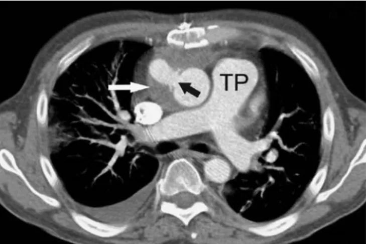
The CT protocol was chosen according to the respective indication. If haemorrhage was suspected, we used a three-phase CT protocol, including an unenhanced image to allow measurement of CT attenuation in potential fluid collections. The same protocol was used when pseudoan-eurysm formation at the anastomosis site or thrombosis of the device was suspected. We suggest that unenhanced images are used for visualising the metallic parts of the CAD systems and to differentiate potential vessel calcifica-tions from contrast-enhanced structures. The arterial phase of contrast enhancement was very helpful for the depiction of the in- and outflow cannulae of the CAD systems and the great vessels of the heart. The venous phase of contrast enhancement was added for evaluation of the anastomoses of the in- and outflow cannulae with regard to possible pseudoaneurysms or contrast media extravasation. We advise a single venous phase of contrast enhancement in those patients for whom the aim was to rule out a focus of infection. When pneumonia was suspected, only unen-hanced CT was performed. From our experience, the use of a flexible CT imaging protocol adjusted to the individual clinical indication appears more adequate than using a fixed three-phase protocol, particularly for avoiding Fig. 5 A 56-year-old male patient who underwent surgery for an
intracorporeally placed Micromed-DeBakey LVAD as a bridge-to-transplant. Axial computed tomography reconstruction at the level of the pulmonary trunk (TP) demonstrates a mediastinal haematoma (white arrow) surrounding the intact anastomosis of the outflow cannula, connecting the device to the ascending aorta (black arrow)
Fig. 6 A 47-year-old male patient who underwent surgery for an intracorporeally placed Berlin Heart Incor as a bridge-to-transplant. Axial computed tomography reconstruction at the level of the left (LA) and right (RA) atrium demonstrates an infected fluid collection in the anterior mediastinum with peripheral contrast enhancement (white thin arrows). Note the correct positioning of the inflow cannula (black arrow) in the left ventricle (LV), the outflow graft in its course to the ascending aorta (thick white arrow), and pacemaker electrodes in the RA and right ventricle
unnecessary radiation exposure. Electrocardiography (ECG) gating was not used in any patient because evaluation of the coronary arteries was not the focus of these CT examinations. Nevertheless, when imaging of coronary arteries or of potential coronary artery bypass grafts is required, the CT data acquisition should be synchronised to the ECG. The electrical conduction system of the native heart is in good order in most of the patients and works independently from the assist device [29]. Furthermore, the use of ECG synchronisation in patients with a CAD may improve the image quality by reducing motion artefacts [29].
Complications
The incidence of complications associated with the implantation of CAD is approximately 67% and includes haemorrhage, heart failure, renal dysfunction, infection, neurological events, thromboembolic events, as well as thrombosis and air embolism [30,31]. Device failure can be life-threatening and requires device exchange. In the REMATCH study [32], 17% of deaths were caused by device failure. The mortality in patients requiring BVAD as a bridge-to-transplant has been reported to be more than 40% in contrast to the 25% mortality of patients bridged on LVAD [33]. Generally, conventional radiography and CT are both useful techniques that may aid in the detection of complications [11,34], whereas CT is superior in charac-terisation of these complications such as haemorrhage and infections.
Haemorrhage
Haemorrhage occurs either as an early event following surgery or later due to a connection insufficiency. Haemorrhage may appear as abnormal circumferential density surrounding a device and/or its cannulae (Fig.5). There is evidence that the inner surface of LVAD contributes to the bleeding tendency of the activating platelets, along with evidence that LVAD themselves initiate the activation of the fibrinolytic pathway [34]. Mechanisms that alter the tendency to bleed are routine anticoagulation, platelet inhibition, hepatic dysfunction and a poor nutritional status [34]. However, with the Berlin Heart Excor, it is possible to fully reverse anticoagulation
after implantation that may result in a low incidence of haemorrhage which has been one of the major surgical obstacles in the early experience with CAD [35].
Infections
Infectious complications, which are largely caused by the presence of the drive line across the skin barrier, have been reported to occur in almost half of the LVAD recipients [36]. Such complications may occur anywhere along the device itself and all its conduits and connecting cannulae and grafts due to fibrin deposits triggering activity of infecting organisms. Infection may appear as a loculated fluid collection adjacent to a device part (Fig.6).
Thromboembolism
A source of embolism may be the pump itself and its artificial cardiac valves, as well as the native chambers or valves of the heart. Thromboembolism often causes neurologic complications.
Conclusions
Patients with end-stage heart failure may receive mechan-ical circulatory support by implantation of a CAD intended for bridge-to-transplant, bridge-to-recovery or as a perma-nent alternative to heart transplantation. CAD therapy is a continuously evolving field with an increasing number of implantations over the last 20 years. The Micromed-DeBakey LVAD, the Berlin Heart Incor LVAD and the Berlin Heart Excor are frequently implanted artificial blood pumps. Every CAD has its own footprint that produces a specific radiological appearance on conventional radiog-raphy and CT. CT is the modality of choice that comprehensively allows one to delineate the in- and outflow cannulae and positioning of the blood pump itself, as well as potential CAD-associated complications like mediastinal haemorrhage, infection and thromboembolism.
Acknowledgements This research has been supported by the National Center of Competence in Research, Computer Aided and Image Guided Medical Interventions (NCCR CO-ME) of the Swiss National Science Foundation.
References
1. Mendez GF, Cowie MR (2001) The epidemiological features of heart failure in developing countries: a review of the literature. Int J Cardiol 80:213–219
2. Hunt SA, Baker DW, Chin MH et al (2002) ACC/AHA guidelines for the evaluation and management of chronic heart failure in the adult: executive summary. J Heart Lung Transplant 21:189–203
3. Hetzer R, Jurmann MJ, Potapov EV et al (2002) Heart assist systems—current status. Herz 27:407–417
4. Gray NA Jr, Selzman CH (2006) Cur-rent status of the total artificial heart. Am Heart J 152:4–10
5. Hall CW, Liotta D, Henly WS, Crawford ES, Debakery ME (1964) Development of artificial intrathoracic circulatory pumps. Am J Surg 108:685–692
6. Frazier OH, Rose EA, Oz MC et al (2001) Multicenter clinical evaluation of the HeartMate vented electric left ventricular assist system in patients awaiting heart transplantation. J Thorac Cardiovasc Surg 122:1186–1195 7. DeBakey ME (1971) Left ventricular
bypass pump for cardiac assistance. Clinical experience. Am J Cardiol 27:3–11
8. Drews T, Loebe M, Jurmann M, zu Dohna R, Erben M, Hetzer R (2001) Outpatients on biventricular assist de-vices. Thorac Cardiovasc Surg 49:296– 299
9. Frazier OH, Jacob LP (2007) Small pumps for ventricular assistance: progress in mechanical circulatory support. Cardiol Clin 25:553–564, vi 10. Frazier OH, Delgado RM (2003)
Me-chanical circulatory support for ad-vanced heart failure: where does it stand in 2003? Circulation 108:3064– 3068
11. Jain VR, White CS, Pierson RN 3rd, Griffith BP, Sorensen EN (2005) Im-aging of left ventricular assist devices. J Thorac Imaging 20:32–40
12. Stone ME (2007) Current status of mechanical circulatory assistance. Semin Cardiothorac Vasc Anesth 11:185–204
13. Cascade PN, Meaney JF, Jamadar DA (1997) Methods of cardiopulmonary support: a review for radiologists. Radiographics 17:1141–1155 14. Lietz K, Miller LW (2004) Left
ven-tricular assist devices: evolving devices and indications for use in ischemic heart disease. Curr Opin Cardiol 19:613–618
15. Song X, Throckmorton AL, Untaroiu A et al (2003) Axial flow blood pumps. Asaio J 49:355–364
16. Yacoub MH, Miller LW (2008) Long-term left-ventricular-assist-device ther-apy is here to stay. Nat Clin Pract Cardiovasc Med 5:60–61
17. Helman DN, Addonizio LJ, Morales DL et al (2000) Implantable left ven-tricular assist devices can successfully bridge adolescent patients to transplant. J Heart Lung Transplant 19:121–126 18. Birks EJ, Tansley PD, Yacoub MH et al
(2004) Incidence and clinical manage-ment of life-threatening left ventricular assist device failure. J Heart Lung Transplant 23:964–969
19. Allen GS, Murray KD, Olsen DB (1997) The importance of pulsatile and nonpulsatile flow in the design of blood pumps. Artif Organs 21:922–928 20. Schmid C, Jurmann M, Birnbaum D et
al (2008) Influence of inflow cannula length in axial-flow pumps on neuro-logic adverse event rate: results from a multi-center analysis. J Heart Lung Transplant 27:253–260
21. Wilhelm MJ, Hammel D, Schmid C et al (2005) Long-term support of 9 patients with the DeBakey VAD for more than 200 days. J Thorac Cardiovasc Surg 130:1122–1129 22. Cooper DS, Jacobs JP, Moore L et al
(2007) Cardiac extracorporeal life sup-port: state of the art in 2007. Cardiol Young 17(Suppl 2):104–115 23. Gandhi SK (2009) Ventricular assist
device in children. Prog Pediatr cardiol 26:11–99
24. Aaronson KD, Patel H, Pagani FD (2003) Patient selection for left ven-tricular assist device therapy. Ann Thorac Surg 75:S29–S35
25. Bean MJ, Pannu H, Fishman EK (2005) Three-dimensional computed tomo-graphic imaging of complex congenital cardiovascular abnormalities. J Comput Assist Tomogr 29:721–724
26. Leschka S, Oechslin E, Husmann L et al (2007) Pre- and postoperative evaluation of congenital heart disease in children and adults with 64-section CT. Radiographics 27:829–846 27. Knisely BL, Collins J, Jahania SA,
Kuhlman JE (1997) Imaging of ven-tricular assist devices and their com-plications. AJR Am J Roentgenol 169:385–391
28. Knollmann FD, Loebe M, Weng Y et al (1999) Radiologic anatomy of ventric-ular assist devices. J Thorac Imaging 14:293–299
29. Knollman FD, Halfmann R, Regn J et al (1999) Motion artifacts in cardiac CT. The Novacor left ventricular assist device and its implications for clinical imaging. Acta Radiol 40:569–577 30. Kavarana MN, Pessin-Minsley MS,
Urtecho J et al (2002) Right ventricular dysfunction and organ failure in left ventricular assist device recipients: a continuing problem. Ann Thorac Surg 73:745–750
31. Lazar RM, Shapiro PA, Jaski BE et al (2004) Neurological events during long-term mechanical circulatory sup-port for heart failure: the Randomized Evaluation of Mechanical Assistance for the Treatment of Congestive Heart Failure (REMATCH) experience. Cir-culation 109:2423–2427
32. Rose EA, Gelijns AC, Moskowitz AJ et al (2001) Long-term mechanical left ventricular assistance for end-stage heart failure. N Engl J Med 345:1435– 1443
33. Tsukui H, Teuteberg JJ, Murali S et al (2005) Biventricular assist device utilization for patients with morbid congestive heart failure: a justifiable strategy. Circulation 112:I65–I72 34. Piccione W Jr (2000) Left ventricular
assist device implantation: short and long-term surgical complications. J Heart Lung Transplant 19:S89–S94 35. Warnecke H, Berdjis F, Hennig E et al
(1991) Mechanical left ventricular support as a bridge to cardiac trans-plantation in childhood. Eur J Cardiothorac Surg 5:330–333
36. Sinha P, Chen JM, Flannery M, Scully BE, Oz MC, Edwards NM (2000) Infections during left ventricular assist device support do not affect posttrans-plant outcomes. Circulation 102: III194–III199