HAL Id: hal-00590410
https://hal.archives-ouvertes.fr/hal-00590410
Submitted on 11 Mar 2015
HAL is a multi-disciplinary open access
archive for the deposit and dissemination of
sci-entific research documents, whether they are
pub-lished or not. The documents may come from
teaching and research institutions in France or
abroad, or from public or private research centers.
L’archive ouverte pluridisciplinaire HAL, est
destinée au dépôt et à la diffusion de documents
scientifiques de niveau recherche, publiés ou non,
émanant des établissements d’enseignement et de
recherche français ou étrangers, des laboratoires
publics ou privés.
Nanoporous beta-PVDF membranes with selectively
functionalized pores
Olivia Cuscito, M.C. Clochard, Stéphane Esnouf, Natacha Betz, Didier Lairez
To cite this version:
Olivia Cuscito, M.C. Clochard, Stéphane Esnouf, Natacha Betz, Didier Lairez. Nanoporous
beta-PVDF membranes with selectively functionalized pores. Nuclear Instruments and Methods in Physics
Research Section B: Beam Interactions with Materials and Atoms, Elsevier, 2007, 265, pp.309-313.
�10.1016/j.nimb.2007.08.089�. �hal-00590410�
Nanoporous β-PVDF membranes
with selectively functionalized pores ?
O. Cuscito , M.-C. Clochard ∗ , S. Esnouf , N. Betz
LSI, Ecole Polytechnique, CEA-DSM, CNRS, 91128 Palaiseau cedex, France
D. Lairez
Laboratoire L´eon Brillouin, CEA-Saclay, 91191 Gif-sur-Yvette cedex, France
Abstract
Poly (vinylidene fluoride) (β-PVDF) nanoporous membranes are obtained by heavy ion irradiation and track etching leading to cylindrical pores. Pores diameter measured by Scanning Electron Microscopy and Small Angle Neutron Scattering lies in the 20-50 nm range. Electron Paramagnetic Resonance study gives evidence that radicals still remains in PVDF membrane after track-etching. These radicals allows acrylic acid polymerization to be initiated onto membrane. So radiografted and functionalized membranes are characterized using Infrared Spectroscopy, weighing measurements and Energy Dispersive Spectroscopy. Finally, radiografted poly(acrylic-acid) (PAA) has been selectively labeled by fluorophores and imaged by Confocal Laser Scanning Microscopy. Images show the localisation of PAA specifically inside nanopores.
Key words: β-PVDF Membranes, Swift heavy ions, Nanopores, Poly (acrylic acid) PACS: 81.07.-b, 82.45.Mp, 61.80.Lj
1. Introduction
Swift heavy ion irradiation of polymers offers many applications depending on ion species, specific energy of ion, particle flux and fluence. Nanoporous membranes is an application field of increasing inter-est [1]. With the aim of preparing such membranes, irradiation of poly(vinylidene fluoride) (PVDF) in β-phase is particularly interesting due to: 1)biocom-patibility; 2)excellent chemical properties of PVDF. However, PVDF hydrophobicity restricts possible applications in aqueous media such as those for biological applications. Different methods can be
? Supported by the french Ministry of Scientific Research (ACI ”nanoscience” 2003, grant n◦120).
∗ Corresponding author:
applied to modify membranes surface. Among these methods, radiografting polymerization consists in either creating active sites by γ-irradiation [2,3], or plasma treatment [4], or electron irradiation [5] and then initiate polymerization with hydrophilic groups. In different works, Mazzei et al. displayed polymerization should be initiated from active sites remaining after etching.
In this paper, we prove by Electron Paramagnetic Resonance study that in the case of PVDF mem-branes, the radicals formed all along ion-tracks are very stable and remain significantly present around pore-walls after track etching. These radicals allow us to initiate acrylic acid polymerization and specific pore functionalization. This latter feature has been evidenced by Confocal Scanning Laser Microscopy (CSLM).
2. Materials and methods
Materials: Poly(vinylidene fluoride) (PVDF)
films of 9 µm thickness were kindly provided by Solvay, Belgium. Toluene, potassium hydroxide,
potassium permanganate, potassium disulfite,
acrylic acid (AA), Mohr’s salt ((NH4)2Fe(SO4)2
6H2O), sulphuric acid, EDC (C8H17N3HCl),
phos-phate buffer saline (PBS), tBuOK (C4H9OK 95%)
were purchased from Sigma-Aldrich. Alexa Fluor R
488 hydrazide (C21H15N4NaO10S2) was purchased
from Invitrogen.
Irradiations: Before irradiations, β-PVDF films are toluene-extracted for 24 h. PVDF films were electron irradiated using a Van de Graaff accelerator (absorbed dose of 100 KGy, under He atmosphere). Swift heavy ion irradiations were performed at the GANIL, Caen. Films were irradiated with Kr ions
(10.37 Mev/amu, fluence 107 and 5 × 108cm−2)
under He atmosphere. In two cases, samples were
stored at -20◦C under N2atmosphere until chemical
etching and radiografting.
Chemical etching: β-PVDF irradiated films were chemically etched using permanganate solution (0.25 M) in a highly alkaline medium (KOH, 10 M)
at 65◦C with different etching times from 0.5 to
3 h. Membranes obtained were washed in potassium
disulfite solution (15%) then dried at 50◦C under
vacuum.
Radiografting: β-PVDF film of initial size
20×20 mm2, is weighted. Film is immersed at room
temperature into a radiografting solution contain-ing acrylic acid and Mohr’s salt (0.25%w/w). After 15 min of bubbling nitrogen at room temperature, sample container is introduced in a thermostated
water bath at 60◦C for 1 h. Film is washed with
water and then Sohxlet-extracted in boiled water in order to extract free homopolymer. Once dried at
50◦C under vacuum, the radiografting yield, Y =
(mf − mi)/mi is calculated with mi and mf the
weight before and after radiografting, respectively.
Infra-red spectroscopy: FTIR spectra of PVDF
were obtained with a Nicolet Magna-IR 750 spec-trometer equipped with a DGTS detector. Measure-ments were performed at the Brewster’s angle to eliminate interference fringes. To analyse the first micrometers of the film, spectra were recorded in an Attenuated Total Reflexion mode (ATR) using a diamond-crystal with single reflection. Spectra were collected by cumulating 32 scans at a resolution of 2 cm−1.
Electron Paramagnetic Resonance (EPR): EPR spectra were recorded at the X band (9.4 GHz) on a
Br¨uker ER-200D EPR spectrometer. β-PVDF
mem-branes were analysed before, after etching and after
annealing at to 65◦C.
Fluorescein diffusion: β-PVDF membrane
sep-arates an upstream compartment with fluorescein solution (1 mM), from a downstream compartment with pure water. Increase of fluorescein concentra-tion, C, in the downstream compartment is mea-sured by UV spectroscopy. In both compartments, a
stirring was applied. Typically, C = C∞(1 − e−t/τ),
with C∞ the equilibrium concentration and τ the
characteristic diffusion time of fluorescein through
the membrane. Denoting Am the membrane area,
the effective exchange area is A = Amnπr2, with n
the fluence and r the pore radius. Denoting, V the harmonic mean volume of the two compartments, ∆x the thickness of the membrane and D = (430 ± 30) × 10−8cm2/s [6] the diffusion coefficient of fluo-rescein, the measured characteristic time writes τ = V ∆x/(2A × D), allowing pore radius to be calcu-lated.
Small Angle Neutron Scattering (SANS): Mea-surements were performed on PACE spectrometer at LLB (CEA-Saclay). For each measurements, 18
identical β-PVDF membranes of 1×1 cm2 (9 µm
thickness, fluence 5 × 108cm−2) were stacked to
increase neutron scattered intensity recorded as a function of scattering vector. Data treatment was performed following ref.[7]. Scattered intensity profil is accounted for using the form factor of cylinder [8], narrow distribution of orientations and convolved by spectrometer resolution [9]. Measurements were performed for membranes obtained with different etching times: 15, 20, 25 and 35 min, respectively.
Scanning Electron Microscopy (SEM): SEM were performed with a Philips apparatus equipped with a LaB6 tip (LMS, Ecole Polytechnique). This appa-ratus is coupled with PGT-Princeton Gamma Tech X-ray detector (EDS) and a PRISM Digital spec-trometer. Samples were immersed within a potas-sium ter-butoxide solution (50%w/w). Purple col-oration appears of intensity varying with the radio-grafting yield. Films were embedded in EPON resin before being cut by a Leica microtome. Then, pro-files of cross-section can be imaged. Each sample is coated with Au layer.
Confocal Scanning Laser Microscopy (CSLM): Measurements were performed at LLB with a Le-ica TCS-SP2 using a Ar laser (488 nm). Samples were observed in water with a 40× dry objective of 2
numerical aperture 0.85.
3. Results
3.1. Nanopores diameter
Nanopores diameter of β-PVDF membranes was determined by SEM, SANS and fluorecein diffusion measurements for different etching time.
In Fig.1, a typical SEM image is shown for pores diameter of 30 nm. Below this size, pores diameter becomes difficult to evaluate by SEM. Two addi-tional limitations are inherent to this technique: 1) only surface information are obtained; 2) statistics over macroscopic length scales is difficult to achieve.
Fig. 1. SEM image of the surface of a typical track etched β-PVDF membrane: fluence 5 × 108cm−2, etching time
25 min.
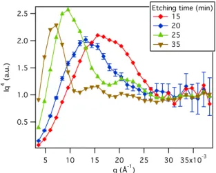
In Fig.2, SANS spectra obtained for pores diam-eter between 20 and 50 nm are plotted as a function of scattering vector q. For each spectra, the position,
q∗, of the maximum is proportional to the reverse
diameter, 1/φ. One has: q∗ ' 4/φ. Pores
diame-ter smaller than 20 nm should be easily measured. Compared to SEM, note that: 1) SANS provides in-formations concerned with the bulk of membranes; 2) SANS signal is directly an average on sample of macroscopic size.
In Fig.3, results obtained by the different meth-ods are compared. In addition, pores diameter de-duced from measurements of fluorescein diffusion through membranes are plotted. SEM results suffer from small size limitations and important error bars, whereas measurements of fluorescein diffusion show huge error bars. Actually, these latter measurements
are concerned with very long diffusion time (sev-eral days). Then temperature stability and the cor-responding convection problems cannot be avoided. Finally, SANS gives the best results.
Fig. 2. Small angle neutron scattering intensity, I, multiplied by q4 vs. scattering vector q for β-PVDF membrane with
different etching times. For increasing etching time, a shift of the maximum of the spectra to lower q values indicates increasing pores diameter.
Fig. 3. Pores diameter, φ, of β-PVDF membrane vs. etching time. Measurement performed by SEM, SANS and Fluores-cein diffusion. Straight line is the best linear fit of SANS results: φ = (1.43 ± 0.04) × t.
3.2. Radicals after chemical etching
During chemical etching at 65◦C, radicals amount
decreases with time because of a loss of matter, but they are still present in the membrane after etching.
This was evidenced by Electron Paramagnetic Reso-nance (EPR) (see Fig.4). We observed that approxi-mately 20% of radicals initially present in irradiated membrane remain present after 1 h of etching. Note that this etching time corresponds to pores of 85 nm diameter (see section 3.1). The nature of these
rad-icals is known [10,11]: alkyl radrad-icals (in-chain -CF2
-C•H-CF
2- and end-chain -CF2-C•H2), peroxy
radi-cals (POO•). These actives sites are able to initiate
radiografting and polymerization of acrylic acid.
Fig. 4. Electron Paramagnetic Resonance (EPR) spectra per mass unit (mg−1) for heavy ions irradiated film before etch-ing (latent tracks) and after 1 h track etchetch-ing. In this latter case, non-horizontal baseline is due to paramagnetic impu-rities (KMnO4 from etching bath).
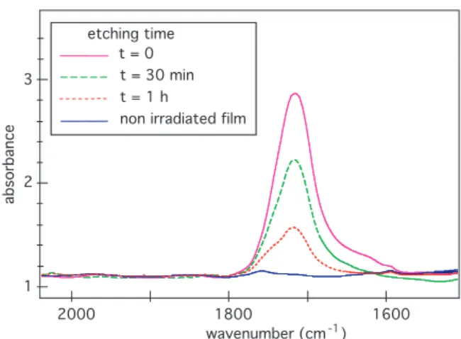
In order to assert the existence of radicals after chemical etching, samples allowing FTIR spec-troscopy measurements to be performed were specially prepared: film thickness 25 µm, fluence
109cm−2, radiografting with 100% AA. FTIR
spectra of these PVDF-g-PAA membranes show a characteristic band for the O-C=O stretching
(ν = 1710 cm−1) related to the COOH groups of
radiografted PAA chains (see Fig.5).
3.3. Radiografting: pore-wall modeling by electron irradiated films
The passage of one swift heavy ion through PVDF film comes with energy transfer. Above ion energy of the order of 0.1 MeV/mau, this transfer is mainly electronic. It results in damage-zones of two species [12]:
(i) Atomic collision-cascades over distances from ion trajectory of the order of 0.01 µm forms the track-core that is a highly damaged zone.
wavenumber (cm )-1 absorbance etching time t = 0 t = 30 min t = 1 h
non irradiated film
2000 1800 1600
3
2
1
Fig. 5. FTIR spectra of swift heavy ion irradiated PVDF-g– PAA for different etching times (AA concentration 100%v/v, fluence 109cm−2, Mohr’s salt 0.25%w/w, radiografting at
60◦C for 1 h). The maximum corresponds to O-C=O stretch-ing (ν = 1710 cm−1) and gives evidence for COOH groups of radiografted PAA chains.
(ii) Electronic collision-cascades over larger dis-tances form the trak-shell. This zone is en-larged up to a diameter of the order of microm-eter.
After track etching, only this latter damaged zone participates to the pore-wall (see Fig.6). In the case of electron irradiation, bulk and surface of the film are homogeneously irradiated leading to damages of the second species. Thus, with respect to radiograft-ing properties, similar behavior are expected for ion irradiated films after track etching and electron ir-radiated films. Such modeling allows us a quantita-tive study of radiografting that should be difficult otherwise (the radicals amount determined by EPR after electron irradiation is 13 times higher than the
one after ion irradiation at fluence of 5 × 108cm−2).
PVDF film
before etching after etching track-shell: electronic collision-cascades track-core: atomic collision-cascades pore-wall PVDF film Fig. 6. Schematic representation of an ion track before and after etching. For heavy ion irradiation of PVDF film, the particular ”core-shell” structure of ion track, allows us to use electron irradiated film as model of pore-wall.
Radiografting of PAA on PVDF after electron ir-radiation has been already studied in detail [13]. In Fig.7 for electron and ion irradiated films, the varia-4
tion of PAA radiografting yield is plotted as a func-tion of the AA concentrafunc-tion in the reacfunc-tion bath. Apart from a shift of the maximum, the shape of the two curves is the same: radiografting yield linearly increases with AA concentration up to 50%v/v; then it increases more rapidly until a maximum and fi-nally decreases. In case of etched foils, the grafting yield displays similar curve (versus AA concentra-tion) at a smaller scale. This behavior has been al-ready observed for α-PVDF. It is due to coopera-tive effects of solvent and monomer diffusion inside PVDF film [13].
Fig. 7. Radiografting yield vs. AA concentration. Open sym-bols: ion irradiated film, at 100 kGy. Full symsym-bols: Kr ion irradiated film, fluence 5 × 108cm−2, no etching.
Radiograft-ing at 60◦C for 1 h.
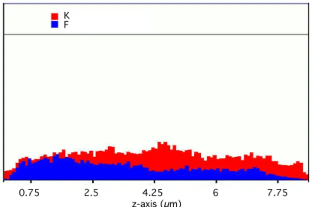
This latter point is illustrated by Energy Disper-sive Spectroscopy (EDS) study of film cross-section. Fig.8 shows EDS profiles for β-PVDF-g-PAA films obtained after electron irradiation for acrylic acid concentration of 5%v/v. It appears that monomers reach the inner part of the film, leading to an ho-mogeneous radiografting. For this AA concentra-tion, radiografted pore-walls presumably also ex-hibit a zone of closely interpenetrated PAA and PVDF chains (see Fig.9).
3.4. Visualization of labelled PAA radiografted pores by CLSM
Classical analysis techniques of radiografting such as those used in section 3.2, cannot be used for thin PVDF membranes and low fluence. Confo-cal Laser Scanning Microscopy (CLSM) was used. This technique provides three dimensions images of structures or objets labeled by fluorescent molecules
0.75 2.5 4.25 6 7.75 m icrons 0.75 2.5 4.25 6 7.75 m icrons Fig.7. 0 2.25 4.5 6.75 9 11.25 m icrons 0 2.25 4.5 6.75 9 11.25 m icrons Fig.8. 0.75 2.5 4.25 6 7.75 z-axis (µm) K F
Fig. 8. Cross-section EDS profiles (red: potassium, blue: flu-orine atoms) of PVDF-g-PAA films initially electron irradi-ated at 100kGy, radiografted at 60◦C for 1 h (AA concen-tration 5%v/v, grafting yield 9%w/w) with 0.25%w/w of Mohr’s salt and treated in solution of tBuOK (50%w/w).
membrane
pore
PVDF
PAA
Fig. 9. Schematic representation of pore wall structure made of interpenetrated PVDF and radiografted PAA.
beforehand. Laser causes fluorophores excitation and the consecutive fluorescence of the focal volume (voxel) is measured. Three dimensional scanning of this voxel provides 3D images.
In our case, radiografted PAA can be labeled by
Alexa Fluor R hydrazide specially designed for
car-boxyl group labeling. However, etching bath is ox-idative and responsible for the formation of carboxyl group at the surface of film. In order to differentiate the two carboxyl group species (PAA carboxyl and oxydated PVDF carboxyl), the following method was used:
(i) After track etching and before PAA radio-grafting, oxydated PVDF carboxyl groups are
modified with ethylenediamine (NH2-CH2
-CH2-NH2) leading to primary amine groups
at the surface of the film.
(ii) Membrane is then radiografted with PAA. Surface amine groups can be revealed by fluores-cein isothiocyanate (FITC) labeling. FITC is a fluo-rophore that specifically reacts with primary amine groups. The corresponding CLSM image is shown in Fig.10 top. PAA carboxyl groups are revealed by
10 µm
10 µm
Fig. 10. CLSM images of labeled PVDF-g-PAA films modi-fied with ethylenediamine before grafting. Images are xz-plan (cross-section) reconstructions of series of xy slices. z axis has been rescaled to account for refractive index of PVDF. Top: fluorescein isothiocyanate labeling reveals amine groups, i.e. surface oxydation. Bottom: Alexa Fluor R hydrazide
label-ing reveals carboxyl group, i.e. poly(acrylicacid).
Alexa Fluor R hydrazide labeling. The
correspond-ing CLSM image is shown in Fig.10 bottom. These images show that radiografting of polyacrylic acid is selectively achieved inside membrane nanopores.
4. Conclusion
This paper is concerned with poly(acrylic acid) radiografting on track-etched, 9 µm thick, β-PVDF membranes. Pores diameter lies in the range
20-50 nm depending on etching time, as measured by Small Angle Neutron Scattering. Our key results is to quantify that radicals produced by heavy ion irra-diation still remain in PVDF films after track etch-ing. These radicals are radially distributed along ion-tracks and allows us to specifically functionalize pore-walls by poly(acrylic acid) radiografting. This specific functionalization was evidenced for the first time by fluorescence labeling and Confocal Laser Scanning Microscopy. Membranes so functionalized have many potential applications: hydrophilic pores for aqueous solution applications (such as biological applications), single pore visualization for nanoflu-idic and nanofiltration physics.
References
[1] P. Apel, Swift ion effects in polymers: industrial applications., Nuclear Instr. Meth. Phys. Res. B 208 (2003) 11–20.
[2] N. Shtanko, V. Kabanov, P. Apel, M. Yoshida, The use of radiation-induced graft polymerization for modification of polymer track membranes., Nuclear Instr. Meth. Phys. Res. B 151 (1999) 416–422.
[3] R. Mazzei, E. Smolko, D. Tadey, L. Gizzi, Radiation grafting of nipaam on pvdf nuclear track membranes, Nuclear Instr. Meth. Phys. Res. B 170 (2000) 419–426. [4] P. Wang, K. L. Tan, E. T. Kang, K. G. Neoh, Plasma-induced immobilization of poly(ethylene glycol) onto poly(vinylidene fluoride) microporous membrane, Journal of Membrane Science 195 (2002) 103–114. [5] F. Liu, B.-K. Zhu, Y.-Y. Xu, Improving the
hydrophilicity of poly(vinylidene fluoride) porous membranes by electron beam initiated surface grafting of aa/sss binary monomers, Applied Surface Science In Press, Corrected Proof.
[6] P. H. Paul, M. G. Garguilo, D. J. Rakestraw, Imaging of pressure and electrokinetically driven flows through open capillaries., Anal. Chem. 70 (1998) 2459–2467. [7] A. Brˆulet, D. Lairez, A. Lapp, J. P. Cotton,
Improvement of data treatment in sans., accepted for publication in J. Appl. Cryst.
[8] A. Guinier, G. Fournet, Small-angle scattering of X-rays., J. Wiley & sons, 1955.
[9] D. Lairez, R´esolution d’un spectrom`etre de diffusion de neutrons aux petits angles., J. Physique IV France 9 (1999) 67–81.
[10] E. Petersohn, Ph.D. thesis, University Pierre et Marie Curie, Paris VI, France (1995).
[11] N. Betz, E. Petersohn, A. Le Moel, Swift heavy ions effects in fluoropolymers: radicals and crosslinking, Nuclear Instr. Meth. Phys. Res. B 116 (1996) 207–211. [12] R. Spohr, Ions Tracks and Microtechnology: Principles and Application., Friedr. Vieweg & Sohn Verlegsgschaft mbH, Braunschweig, 1990.
[13] M. C. Clochard, J. Begue, A. Lafon, D. Caldemaison, C. Bittencourt, J. J. Pireaux, N. Betz, Tailoring bulk
and surface grafting of poly(acrylic acid) in electron-irradiated pvdf, Polymer 45 (2004) 8683–8694.