HAL Id: halshs-00465621
https://halshs.archives-ouvertes.fr/halshs-00465621
Preprint submitted on 20 Mar 2010
HAL is a multi-disciplinary open access
archive for the deposit and dissemination of sci-entific research documents, whether they are pub-lished or not. The documents may come from teaching and research institutions in France or abroad, or from public or private research centers.
L’archive ouverte pluridisciplinaire HAL, est destinée au dépôt et à la diffusion de documents scientifiques de niveau recherche, publiés ou non, émanant des établissements d’enseignement et de recherche français ou étrangers, des laboratoires publics ou privés.
Carbon Capture and Storage (CCS) Technologies and
Economic Investment Opportunities in the UK
Julien Chevallier
To cite this version:
Julien Chevallier. Carbon Capture and Storage (CCS) Technologies and Economic Investment Op-portunities in the UK. 2010. �halshs-00465621�
Carbon Capture and Storage (CCS) Technologies and
Economic Investment Opportunities in the UK
Julien Chevallier
1 March 17, 2010Abstract
This article reviews the role played by carbon and capture (CCS) technologies in order to facilitate the transition to low-carbon emitting technologies in the medium term. More precisely, we address the following central questions: how will the development of CCS technologies impact energy policies in order to yield to sustainable energy solutions? At what costs will pollution reductions be achieved? And most importantly, which CCS technologies will turn out to offer the most effective and efficient solution to handle the challenge of the increased demand for energy within the context of the climate change? We critically assess the technology readiness levels of various CCS technologies – post-combustion capture, pre-combustion capture, amine scrubbing, oxyfuel, integrated gasification combined cycle, calcium looping and chemical looping – based on the best available evidence to date.
Keywords: Carbon Capture and Storage; Technology Readiness; Climate Policy.
1
Université Paris Dauphine (CGEMP/LEDa), Place du Maréchal de Lattre de Tassigny 75775 Paris Cedex 16, France. Email : julien.chevallier@dauphine.fr
1. Introduction
Greenhouse gases (water vapor, carbon dioxide, methane, nitrous oxide, and ozone) retain a share of solar activity as reflected by the earth and contribute to maintain an ambient temperature compatible with the development of life. Without them, it will oscillate around -20°C.
These gases (GHG) accumulate in the atmosphere, and this increasing concentration leads to global warming. In 1988, following the World Meteorological Association and the United Nations Environment Program, the Intergovernmental Panel on Climate Change (IPCC) has been created. Its primary objective consists in reviewing scientific evidence concerning the interactive processes between emissions and GHG concentrations, scenarios for the evolution of long term emissions, the effects of concentrations on climate events, their impact on human activity, technical solutions to mitigate and to adapt in human societies, the socio-economic and ecological consequences of public policies characterized by various repartitions of depolluting efforts through time. The conclusions of the fourth report (IPCC (2007)) are striking: GHG concentrations have significantly risen since the beginning of the industrial revolution, this phenomenon is in excess of natural variability and may be attributed to human activity ; on the basis of the theoretical understanding of the climate (physics laws), climate modeling yields to the conclusion of an average global warming of the Earth’s climate and to the possibility of important perturbations linked to the speed at which changes occur.
Depending on climate simulations, the Earth’s average global temperature could range between +1.4 and +5.8°C in 2100 compared to 1990, mainly due to the increase in GHG emissions. Melting of the ice caps, sea rise, deserts developments, changes in water cycles and in the rhythm of precipitations, increasing intensity and frequency of extreme climate events (cyclones, storms, heat waves, etc.) are some of the expected consequences of these emissions. Most scientists do not feel confident with explaining the consequences of living in a temperature with permanently 4°C or above the threshold of 550ppm in the atmosphere. Of course, many uncertainties exist concerning the mechanisms at stake and the real dimension of forthcoming events, as well as their impact. These uncertainties however did not prevent the international community to launch a coordination to reduce GHG emissions during the 1992 Rio Framework Convention on Climate Change.
Carbon Capture and Storage (CCS) technologies are attracting increasing interests within the scientific and policy arena, and may be identified as a means to reduce significantly GHG emissions. CCS is a chain of processes that reduces carbon dioxide emitted to the atmosphere after the combustion (or potentially the gasification) of a fossil fuel or other industrial process. It can be applied to a number of industries including cement and steel manufacture, refineries and the chemical industry. However, here, we will focus on the utilisation of CCS within the power industry, as a means to decarbonise the electricity sector. Technologically speaking, each individual step in the CCS chain is feasible and has already been demonstrated on an industrial scale. However, there are no current operations where all steps have been demonstrated together on sufficiently large a scale to be applicable to a power station.
The importance of stimulating private companies to adopt carbon capture technologies has been widely recognised, as seen by the incentives to incorporate CCS technologies in the European Union Emissions Trading Scheme (EU ETS, European Commission (2008)). Investments in CCS technologies are usually assessed through the net present value (NPV) of projects, by weighting the value of CO2 emissions saved (and hence permits sold on the market)
against the costs of installing the capture equipment (Bohm et al. (2007); Kemp and Kasim (2008)). However, Otto and Reilly (2008) argue that simply taking the NPV of a project does not reflect the “true” value of an investment, and that other factors should be considered. For instance, they also consider the time value of money and the option to wait before installing new equipments. Compared to NPV models, Yang and Blyth (2007) propose the modelling alternative with the real options approach, where the development of new CCS technologies with multiple stage investments would be modelled using stochastic variables simultaneously taking into account various sources of uncertainties.
As explained by Bryngelsson et al. (2009), most carbon capture technologies introduce a large thermal penalty2 onto the power plant, so a full integration of the production processes is necessary to minimise efficiency drops. It therefore appears unlikely that large scale carbon capture retrofit will occur without substantial financial assistance. Indeed, despite the costs of installing and operating CCS technologies, such projects still need to yield a profit in order to be implemented.
2
The thermal penalty is defined as the penalty associated with the lower flue gas temperature (see Bryngelsson et al. (2009) for more details).
The remainder of the article is organized as follows. Section 2 presents low carbon technologies. Section 3 details climate policies. Section 4 examines CCS principles. Section 5 assesses technologies readiness levels. Section 6 concludes.
2. Low-Carbon Technologies
A wide range of technologies may be used to reduce the carbon-intensity of power generation. There are no-carbon; low-carbon; and reduced-carbon options.
No-carbon options produce no more CO2 than that used in their manufacture and disposal.
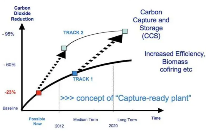
Examples of these are wind, solar, and geothermal technologies. Not all of these technologies are suited to a particular geographical location: the power generated over the lifetime must be enough to pay back the cost of manufacture, installation and operation. No-carbon technologies are often called “renewables”, since the energy that they convert into electrical power is almost unlimited and constantly renewed3. One of the major problems for many sources of renewable energy is their intermittency4 (Turner (1999)). To achieve large-scale power generation from renewables, intermittency must be compensated for by having disparate geographical locations connected to the grid. However, this can introduce instability onto the electricity distribution grid, which requires costly and lengthy upgrades. Since these upgrades typically take 4 to 12 years to be fully operational, the use of renewables must be supported by other electricity sources, such as those classified as low-carbon (which clearly points to the medium-term in Figure 1, see below).
The most prominent and productive forms of low-carbon power generation are nuclear reactors and biomass combustion. Biomass combustion can take a number of forms: at the moment, it is commonly used in co-firing (e.g. coal with biomass)5. Biomass combustion is considered as a low carbon energy source because, although it also releases CO2, this CO2 has
been absorbed from the atmosphere during the plant’s growth. Other forms of biomass-fuelled electricity generation include landfill gas firing. This is where the methane produced by
3
The primary source of this energy is the sun, whether directly through photo-electrical conversion, or indirectly through the generation of convection currents in the air to cause the wind.
4
Installed capacities are capable of providing the average power requirements. However, the actual power output is much lower for the majority of these technologies during their operational life. This is caused by, for instance, the wind not blowing – or blowing too hard – or the sun being hidden during a cloudy day.
5
When used in this manner, biomass is typically compressed to form wood pellets which can be easily transported along the power plants conveyor systems and combust well.
anaerobic digestion of landfill waste is piped off and burnt in an internal combustion engine to provide electricity6. This also produces CO2 but is much better than releasing the methane to the
atmosphere, since methane has a global warming potential four times higher than CO2. Nuclear
has a predominant role to play in the transition towards a low-carbon energy mix. Nuclear is a low-carbon generation technology due to the huge embedded carbon that comes from building, maintaining and security of the site. However, the use of nuclear energy clearly points out the problem of managing nuclear waste, which relates to societies’ choices, and goes far beyond the scope of this article.
Carbon abated technologies are where a certain amount of CO2 is removed from the
pollution caused by generation. This is done by CCS, whereby the CO2 is captured before it
would have been emitted to the atmosphere and then deposited for indefinite periods of time in a geological storage location. Carbon abatement can also be achieved through increasing energy efficiency in both end-user and generator sides. Some of the most rapid carbon savings, and potential financial savings can be made through improving energy efficiency, since it requires no large technological breakthroughs. Both courses of action are complementary, as depicted in Farley (2007).
6
According to Cheung et al. (2009), the environmental benefits include elimination of 850 metric tons of landfill waste per year.
Figure 1: Two tracks towards decarbonising the electricity sector
Source: Farley (2007)
Note: Track 1 involves efficiency improvements and fuel-switching; Track 2 concerns the jump to CCS technologies.
As defined by Bohm (2006), the concept of capture-ready is not a specific plant design;
rather it is a spectrum of investments and design decisions that a plant owner might undertake
during the design and construction of a plant. Power plant owners and policymakers are
interested in capture-ready plants because they may offer relatively low cost opportunities to
bridge the gap between current coal-fired generation technologies without CO2 capture to future
plants that may be built from the start to capture CO2, and reduce the risks of possible future
regulations of CO2 emissions (see Bohm (2006) for more details)7.
7
As pointed out by a referee, CCS is a transition technology and therefore it appears difficult to introduce renewables in Figure 1. This debate, however, goes beyond the scope of the present article.
3. Current Climate Policies
With the adoption of the Kyoto Protocol in 1998, Annex B countries8 are bound to a reduction of their own greenhouse gas emissions by 5% on average with respect to 1990 levels. As Norway introduced a carbon tax at the national level (Abboud (2008)), the first industrial carbon capture and storage facilities were installed. StatoilHydro (2009) developed a new gas field in Sleipner, where CO2 levels present in natural gas were too high for industrial use. This
example shows that companies which emit CO2 have an incentive to reduce their emissions
through technological innovation. In Denmark and Sweden, a widespread technology shift occurred with a move to wind and hydro electricity generation (Abboud (2008)).
In the UK, the government has been promoting the shift to a low-carbon economy through various policy measures, such as the Non-Fossil Fuel Purchasing Agreement (NFFPA) and Renewable Obligation Certificates (ROCs)9. These mandatory schemes set a minimum amount of power purchased from renewable sources, banded so that 1MW from an immature technology (such as offshore wind) is worth more than 1MW from a mature technology. However, there are currently no policy incentives to increase the financial payback to adopt carbon and capture technologies. For carbon capture to compete with renewable sources, it should be entitled to ROCs for each amount of CO2 saved. The UK government has recently set up a competition to
demonstrate CCS. This will fund one full-scale power plant for the additional costs of fitting CCS, and three candidates have been shortlisted. To qualify, the carbon capture unit must operate on the full power station, with a net output of 300MWe (BERR (2008)) or above. This ambitious
policy has been reinforced by the 2009 Budget, which announced the funding of up to 4 power stations demonstrating carbon capture.
Companies are looking for governments to subsidize their move to carbon capture until it becomes an economically viable technology. Newell and Jaffe (2006) show that if a CCS scheme is fully subsidized, the return on investment for public funds would be worse than if the same investment has been directed to R&D efforts. R&D indeed leads to economic growth, as well as lower costs and higher efficiencies within the CCS sector. Therefore, the government needs to discuss the pros and the cons these various options (demonstration projects vs. subsidizing the
8
Annex B parties are the countries that signed the Kyoto Protocol.
9
According to Bergmann et al. (2004), the financial incentives for private investment in renewable power facilities are created by the use of the Renewable Obligation Certificates (ROCs). Electricity suppliers use these certificates as evidence that the required percentage of sales is matched with eligible green power production.
R&D sector) when deciding on how to allocate funds. Gibbins and Chalmers (2008) argue that CCS should follow a number of tranches before being rolled out globally. As shown in Figure 2, expertise may be exported to developing nations. For instance, the UK is fostering links with China – which is currently installing massive generating capacities of coal-fired power stations – to share expertise in CCS.
Figure 2: Method of delivering CCS throughout the world with responsibility initially placed on developed nations
Source: Gibbins and Chalmers (2008)
As illustrated in Figure 2, Gibbins and Chalmers (2008) suggest a two-tranche model for technology discovery, followed by ‘developed country first’ commercial rollout to build developing country confidence in the technology. It is expected that this approach would have a smaller first tranche followed by a larger second tranche. This should encourage efficient use of capital since it would allow later projects to concentrate on optimisation of plant designs, given experience from Tranche 1 plants to establish design rules that should guarantee plants will work. A two-tranche approach would also allow a gradual build-up of the skilled workforce required to design, construct and operate CCS schemes.
The first tranche of plants should be treated as demonstration projects where full support is provided for the incremental cost of adding capture (and may also be required for the
additional base-plant cost of unproven technologies such as IGCC. For this first tranche, one key priority is the speed of deployment. It is expected that a relatively small number of plants could be established, demonstrating a range of concepts. The earliest plants would represent a scale-up from pilot tests, but may be smaller than typical sizes for current commercial units, possibly as low as 100MW. It would, however, be expected that later plants would reach commercial sizes of at least 300–500MW.
Once supported demonstration to provide proof of concept at commercial scale for a range of technologies has been achieved in the first tranche of deployment, it is expected that a larger second tranche could consist of semi commercial projects. In particular, plant technology details in the second tranche might not be specified. Instead, project developers would be allowed to identify schemes that are most suitable to fulfil their commercial and strategic objectives in the context of an incentive and regulatory framework developed by national governments and/or trans-national bodies such as the EU or the UNFCC to encourage continued development of CCS technologies. In the next section, we detail the main principles behind CCS technologies.
4. CCS Principles
Carbon capture and storage involves the capture of CO2 from its point source by one of a
variety of methods. Subsequently, a pure stream of CO2 is transported to a geological storage
facility to be stored for an indefinite period of time. There are several options available for storage of CO2, with one of the most promising being storage in depleted oil and gas reservoirs.
This process is termed Enhanced Oil Recovery (EOR), and represents a potential stream of revenue for CO2 emitters to offset the cost of capture. Another potential storage site, estimated to
have huge capacity for storage are deep saline aquifers. These are salt-water courses occurring naturally deep underground, where CO2 can be injected, and will eventually dissolve in the water
(prior to eventual mineralisation). Aquifers are a much more promising option for nations which do not have access to oil and gas reservoirs, and which would otherwise have to transport CO2
over huge distances for storage. Finally, another option consists in injecting CO2 into
un-mineable coal seams, where CO2 is adsorbed onto the coal very strongly. The adsorption of CO2
enhanced coal bed methane recovery has potential for improving the economics of the CCS chain.
Capturing CO2 produced from power plants inevitably introduces another duty onto the
power plant, which can either result in a loss of power exported, require an increase in net power production to maintain the rating of the power plant or potentially a very great change in plant complexity, e.g. changing to a chemical looping plant. To minimise these effects, CCS needs to be fully integrated into a power plant at the design stage, so that heat and electricity demands can be met in the most efficient manner. To improve efficiency, it appears also advantageous to increase the starting base efficiency of the power plant through technical improvements – for example RWE have developed a pre-drying technique for lignite fired power plants which increases the net efficiency by 4 points (Moser and Schmidt (2009)). Efficiency improvements decrease the net CO2 produced per MW for power plants, and further technological advances
such as ultra-supercritical power plants may bring further improvements. Capture technologies for CCS are post-combustion capture, pre-combustion capture, amine scrubbing, oxyfuel, integrated gasification combined cycle, calcium looping, and chemical looping. Below is a technical summary of the technologies:
Post-combustion capture
Post-combustion capture is where CO2 is captured after fossil fuels have been burned.
This is often seen as the most useful technology for a retrofit application, as the capture process can be tracked on to the end of a power plant. However, integration is complex and requires forward planning and full integration into the power plant to reduce efficiency penalties and parasitic losses. The fossil fuel, typically coal, is burned in a standard power plant. The flue gas is then potentially passed through a series of cleaning steps to remove particulates, sulphur compounds and NOx before being passed to the CO2 capture island. The CO2 will react with a
chemical sorbent or pass through a membrane, taking it out of the exhaust gas stream. The depleted gas is then exhausted to the atmosphere and the separated CO2 stream compressed ready
for transport to a storage location. Capture efficiencies should be in the region of 90% CO2
removed from the exhaust gas.
Pre-combustion capture involves removing the carbon content of the fuel prior to power generation or burning of the fuel. Solid fuels such as coal and biomass are gasified in a high temperature environment. Gasification achieves higher efficiencies than burning the fuel directly, due to the more efficient thermodynamic cycles employed. In a gasifier, the carbon content of a fuel is converted to carbon monoxide and water is converted to hydrogen. The presence of these two gases at high temperature induces the water-gas shift reaction to take place, and rapidly reaches equilibrium. This gas mixture is called “synthesis gas” (or “syngas”). Impurities are removed from the syngas before being passed to the next stage in the process. The CO2 must then
be separated from the gas mixture by several processes involving chemical adsorption. Hydrogen is then used as the fuel source for combustion, or direct chemical conversion to electricity in a fuel cell.
Amine scrubbing
Amine scrubbing is a chemical absorption method of extracting CO2 from a gas stream
that was developed to remove acid gas impurities from natural gas, and which has the potential to be adapted to treat flue gas streams (Herzog (2000)). Most commercial systems use monoethanol amine (MEA) as the solvent for CO2 capture. Efficient integration appears essential, and could be
greatly improved by the development of solvents with lower regeneration energy requirements (Rao and Rubin (2006)). MEA is also toxic to humans and can cause serious burns, so safety precautions must be made for handling and disposal of spent solvent (European Commission (2009)).
Oxyfuel
Oxyfuel combustion – sometimes called oxycombustion or O2/CO2 recycle combustion –
produces a much cleaner burn by using pure oxygen and recycled flue gas to burn the fuel in, rather than air. A pure stream of oxygen can be produced by an air separation unit (ASU), which cryogenically fractionates the air into O2 and N2, which can then be individually used. The ASU
is power intensive, with the IPCC (2005) reporting typical power consumptions of 200-240kWh/tO2. There are less energy intense ways to separate O2 from air, such as adsorption, but
these are uneconomic for the large-scale oxygen production rates required by power plants. There are a number of pilot plants in operation, notably Vattenfall’s world first complete chain plant at
Schwarze Pumpe in Germany. The plant is a 1600MW lignite-fired power station, with 30MW fitted for CCS demonstration. The CO2 is due to be stored in underground as soon as a suitable
site has been located. Total is also operating a pilot plant in Lacq, France, where they have converted one of the five 30MW steam boilers to an oxyfuelfired one. The captured CO2 is
transported during 27 kilometers, and stored in depleted gas reservoir. It uses existing natural gas infrastructure, and the captured CO2 is pumped at 30bar along the pipe (Total (2009)). The
purpose of these plants is to scale up the technology, and run it continuously for a number of years as an important step between lab-scale pilot tests and industrial scale such as 300MW plants, demonstrating and improving the technology.
Integrated gasification combined cycle (IGCC)
Integrated gasification combined cycle (IGCC) is an advanced power plant that combines the efficiency of gasification technologies with the advanced efficiencies of combined cycle power plants. IGCCs are considered to be more economical for large scale power generation due to higher capital costs per net kW (Rubin and Chen (2007)), meeting a base load demand rather than a marginal power plant meeting peak demand. IGCCs are the most efficient and arguably the least polluting forms of using coal as a power source. However, there are still some technology developments required to enable large-scale power generation from IGCCs. As such, it is seen as more of a medium-term solution to curbing CO2 emissions whilst other technologies are seen as
more immediate solutions. The value for flexibility in an IGCC greatly impacts its design and numerous integrations need to be analysed for trade-offs enabling flexibility if required (Davison (2007)).
Calcium looping
Due to the corrosive nature and high cost of many of the amine-based solvents for removing CO2, cheaper and safer options are being investigated. One of these options is to use
limestone – or calcium carbonate – to absorb the CO2 and release it via a reversible
calcination/carbonation reaction (Abanades and Anthony (2004)).
Due to the efficiency penalties imposed on a power plants thermal output by capture systems, novel ways of capturing the CO2 without these are being developed. Instead of
combusting the fuel in air, it may be combusted in the presence of a metal oxide (Abad and Adanez (2006)). In the next section, we evaluate the development stage of each of these potential CCS technologies.
5. Assessment of Technologies Readiness Levels in the UK
To determine how mature a technology is through the R&D phases, there is a scale ranking each technology from level 1 to level 9. The scale was originally developed by the NASA for classifying its research for space flight and scientific instruments, but has been adapted by the UK Department for Environment, Food and Rural Affairs (DEFRA) to be applicable to UK energy technologies (BERR (2008)), as shown in Table 1.
Table 1: Technology readiness levels (TRL)
TRL Status
1 Basic principles observed and reported
2 Technology concept and/or application formulated
3 Analytical and experimental critical function and/or characteristic proof of concept 4 Technology / part of technology validation in a laboratory environment
5 Technology / part of technology validation in a working environment 6 Technology model or prototype demonstration in a working environment 7 Full-scale technology demonstration in working environment
8 Technology completed and ready for deployment through test and demonstration 9 Technology deployed
Source: DEFRA
We then apply these criteria to the CCS technologies detailed in Section 4:
Reviews of carbon capture technology indicate that amine scrubbing is the most developed technology for CCS. This is mainly due to its long use in industry for cleaning natural gas. Currently, there are a number of industrial-scale sites in operation: from In-Salah in Algeria to Sleipner in Norway – each of these operations sequesters around 1 million tonne of CO2 each
year which otherwise would have been emitted to the atmosphere. However, this is still on a much smaller scale than will be required for power plants operating year-round. Amine scrubbing is the technology chosen by most UK generators who are looking to apply CCS to their current portfolio of power plants, and for new-build coal fired power plants. For example, ScottishPower is operating the first post-combustion capture unit to operate under a range of different amines to test for benefits on scale-up (Scottish Power (2009)). Looking at the TRL table presented above, it seems plausible to establish that amine scrubbing is at level 7. There are concerted efforts to move the technology to level 8 rapidly, through demonstration competitions and public funding opportunities (Gibbins and Chalmers (2008)).
Oxyfuel
Oxyfuel technology has been applied in sectors other than power generation such as glass and steel production. These applications are not yet operated at the scale required for power generation. Although the technological principles are similar, the engineering embedded within the technology needs have to be modified (Amann and Kanniche (2009)). Bouillon and Hennes (2009) calculate that an oxyfuel power plant will be more efficient than post-combustion amine capture, with an efficiency of 36.6% compared to 34.6%. The Vattenfall and Total medium-scale demonstration projects operating in Europe (as detailed in Section 4) are currently used to meet a thermal demand by nearby industry rather than electricity generation. Doosan-Babcock (2009) have also recently started testing a 40MWth plant to demonstrate their technology. As all of the
official information on these projects lists them as pilot-plant scale, ready to be scaled up to demonstration-scale, oxyfuel appears at level 6 on the TRL scoring table.
Integrated gasification combined cycle (IGCC)
IGCC is expected to score 5 on the TRL table, as gasification of coal and biomass is a long-standing industrial process, used in the production of methane and chemicals. As such the individual components of the technology and the system has been well proven. However, there
are some significant hurdles to overcome in scaling up the technology. Some of the challenges that must be addressed for power generation are engineering issues that should be overcome with research and practise. The other major problem with IGCC is low availability. These problems have not deterred developers from investing in IGCC power. There is a proposed IGCC plant hoping for EU funding at Hatfield, UK, providing 900MW of power and capturing 90% of the CO2 emitted. Construction is expected to start in 2009 with power from gasified coal being
produced from 2014, after operating as a CCGT during the gasification island construction phase. The gasifier technology will be provided by Shell, with Selexol used to remove CO2 (Clean
Power Projects (2009)). RWE also plans to build a smaller IGCC at Hürth in Germany, having a net power output of 450MW, to be operable by 2015 (RWE AG (2009)).
Calcium looping
Calcium looping may be classified at levels 4 or 5 on the TRL scale. There have been no announcements of plans by energy companies to pursue calcium looping as a carbon capture technology at this stage. However, there are concerted efforts to commercialise the technology, and recently an international network has been established to further the work (IEA GHG (2009)).
Chemical looping
Chemical looping combustion (CLC) technology is the least mature of each of the options studied. CLC is a unique technology that is being developed from first principles, rather than re-engineered from existing processes like amine scrubbing is. In fact the concept was only first proposed in 2002 as a possible route to decarbonising the electricity sector. Much of the commercial development of CLC is being done by companies who may be able to provide full systems. Alstom have presented preliminary results of their findings, indicating that CLC could be potentially the cheapest capture technology available. Large-scale laboratory tests have been done, such as a 10kW combustor demonstrating 100% CO2 capture and 95% fuel combustion at
Chalmers University, Sweden (Naqvi (2006)). Also a 50kW pilot has been operated and tested by (Ryu and Seo (2005)). Novel techniques utilising CLC are also being tested, such as combustion of solid fuels – chemical looping with oxygen uncoupling (CLOU) (Leion and Jerndal (2009)). Thus, CLC may be classified at level 4 until larger scale tests have been operated.
Further developments
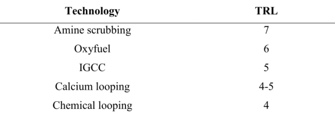
The analysis provided above may be summarized in Table 2, in order to compare explicitly CCS technologies by TRL score.
Table 2: TRL Scoring Tables of CCS Technologies
Technology TRL Amine scrubbing 7 Oxyfuel 6 IGCC 5 Calcium looping 4-5 Chemical looping 4
A post-combustion capture plant is expected to be added to the coal-fired power station in Aalborg in 2013. The capture technology has not yet been chosen and will be decided as late as possible to allow for technology developments throughout the planning stage (Vattenfall (2009)). The UK Carbon Capture and Storage Consortium (UKCCSC) holds regular meetings to keep the knowledge bank up to date and constantly ask the questions: What do we need to do? What is already being done? What is not being done? What can we do to make it happen? The EU has pledged funding towards demonstrating carbon capture with 12 CCS-integrated power plants deployed and operating by 2015 in order to develop carbon capture technology and become a world leader in this area (Hadjipaschalis and Kourtis (2009)). These power plants will at this stage most likely be amine scrubbing, IGCC and oxyfuel power plants as these are the most economically competitive at the moment.
6. Concluding Remarks
This article provides a detailed understanding of the potential for investment into CCS in the UK. This was followed by a thorough overview the main CCS technologies in terms of readiness level. The simplicity of calcium looping and the low cost of the materials and processes
involved make calcium looping an ideal choice for generators to pursue. It seems that there will be a mix of carbon capture solutions in the market, and this competition will drive innovation. We have highlighted a strong background of skills and knowledge readily available for many of the processes involved, so that CCS technologies could rapidly develop. Whilst the first demonstration projects are being implemented, government support may well be required in order to make the technology competitive and commercially viable. However, with learning-by-doing and increasing experience, the second generation of carbon capture plants is expected to be self-sufficient.
Proposed support mechanisms for policymakers include incentivising CO2 capture and
storage (with for example contract for differences, multiple credits, supplementary payments). These effects could have a significant impact on which CCS technologies are attractive, and potentially which investors might be able to invest.
References
Abad, A., and Adanez, J. (2006). Mapping of the range of operational conditions for Cu-, Fe-, and Ni-based oxygen carriers in chemical-looping combustion. Chemical Engineering Science 62, 533-549.
Abanades, J. C., and Anthony, E. J. (2005). Fluidized bed combustion systems integrating CO2 capture with CaO. Environmental Science & Technology 39, 2861- 2866.
Abboud, L. (2008). An exhausting war on emissions. Wall Street Journal, Dow Jones & Company, New York.
Amann, J.-M., and Kanniche, M. (2009). Natural gas combined cycle power plant modified into an O2/CO2 cycle for CO2 capture. Energy Conversion and Management 50, 510-521.
Bergmann, A., Hanley, N., and Wright, R. (2004). Valuing the Attributes of Renewable Energy Investments. Working Paper, University of Glasgow.
BERR (2008). CCS Demonstration Competition: Documentation/Q & A. Available at the following address:
http://www.berr.gov.uk/energy/sources/sustainable/ccs/ccsdemo/docs-qa/page42503.html.
Bohm, M.C. (2006). Capture-ready power plants: options, technologies and economics. Ph.D.
Thesis, Massachusetts Institute of Technology. Technology and Policy Program., Massachusetts
Institute of Technology. Technology and Policy Program.
Bohm, M. C., Herzog, H. J., Parsons, J.E., and Sekar, R.C. (2007). Capture-ready coal plants - Options, technologies and economics. International Journal of Greenhouse Gas Control 1, 113-120.
Bouillon, P.-A., and Hennes, S. (2009). ECO2: Post-combustion or oxyfuel – A comparison between coal power plants with integrated CO2 capture. Energy Procedia 1: 4015-4022.
Bryngelsson, M., Lindfeldt, E.G., and Heller, J. (2009). The modelling of a hybrid combined cycle with pressurised fluidised bed combustion and CO2 capture. International Journal of
Greenhouse Gas Control 3(3), 255-262.
Cheung, C., Bengtson, K., Moser, M., Wu, A., Parrilla, B., and Mastrangelo, C. (2009). Development of a renewable hybrid power generation system. Systems and Information
Engineering Design Symposium, SIEDS’09, 55-60.
Clean Power Projects (2009). Hatfield IGCC. Available at the following address:
http://powerassetmodelling.co.uk/html/hatfield_igcc_.html.
Davison, J. (2007). Performance and costs of power plants with capture and storage of CO2.
Energy 32, 1163-1176.
Doosan-Babcock (2009). Doosan Babcock launches world’s largest OxyCoal™ firing demonstration. Available at the following address:
http://www.doosanbabcock.com/live/dynamic/News2ShowArticle.asp?article_id={56FB5815-644D-44B8-95A8-FC7BAC057D61}&cmetemplate=dynamic/pressreleaseslist.tmp
European Commission (2009). Directive 2009/29/EC, the European Parliament and of the Council.
Farley, M. (2007). Future UK Power generation in a carbon constrained world. Coal Research
Forum 5, 345-356.
Gibbins, J. and Chalmers, H. (2008). Preparing for a global rollout: A 'developed country first' demonstration programme for rapid CCS deployment. Energy Policy 36, 501-507.
Hadjipaschalis, I., and Kourtis, G. (2009). Assessment of oxyfuel power generation technologies.
Herzog, H. J. (2000). The economics of CO2 separation and capture. Technology 7, 13-23.
IEA GHG (2009). High Temperature Solid Looping Cycles Network. Available at the following address: http://www.co2captureandstorage.info/networks/looping1.htm.
IPCC (2005). IPCC Special Report on Carbon dioxide Capture and Storage. Prepared by Working Group III of the Intergovernmental Panel on Climate Change. B. Metz, O. Davidson, H. de Coninck, M. Loos and L. Meyer. Cambridge, UK, New York, NY: 105-178.
IPCC (2007). Climate Change 2007: The Physical Science Basis. Contribution of Working Group I to the Fourth Assessment Report of the Intergovernmental Panel on Climate Change. S. Solomon, D. Qin, M. Manninget al. Cambridge, United Kingdom and New York, NY, USA.
Kemp, A. G. and Kasim, A. S. (2008). A least-cost optimisation model of CO2 capture applied to
major UK power plants within the EU-ETS Framework. The Energy Journal, 99-134.
Leion, H., and Jerndal, E. (2009). Solid fuels in chemical-looping combustion using oxide scale and unprocessed iron ore as oxygen carriers. Fuel 88, 1945-1954.
Moser, P., and Schmidt, S. (2009). Enabling post combustion capture optimization - The pilot plant project at Niederaussem. Energy Procedia 1, 807-814.
Naqvi, R. (2006). Overview of CLC activities outside ENCAP. ENCAP Seminar on CLC, Gothenburg, Sweden.
Newell, R. G., and Jaffe, A. B. (2006). The effects of economic and policy incentives on carbon mitigation technologies. Energy Economics 28, 563-578.
Otto, V. M. and Reilly, J. (2008). Directed technical change and the adoption of CO2 abatement technology: The case for CO2 capture and storage. Energy Economics 30, 2879-2898.
Rao, A. B. and Rubin, E. S. (2006). Evaluation of potential cost reduction from improved amine-based CO2 capture systems. Energy Policy 34, 3765-3772.
Rubin, E. S. and Chen, C. (2007). Cost and performance of fossil fuel power plants with CO2
capture and storage. Energy Policy 35, 4444-4454.
Scottish Power (2009). UK first at Longannet as ScottishPower bring clean coal technology one step closer to reality. Available at the following address:
http://www.scottishpower.com/carbon_capture_storage/docs/press_release_29May09.pdf.
RWE AG (2009). IGCC/CCS power plant. Available at the following address:
http://www.rwe.com/web/cms/en/2688/rwe/innovations/power-generation/cleancoal/ igcc-ccs-power-plant/
Ryu, H.-J., and Seo, Y. (2005). Development of chemical-looping combustion technology: long-term operation of a 50kWth chemical-looping combustor with Ni- and Co-based oxygen carrier particles. Regional Symposium on Chemical Engineering, Hanoi, Vietnam.
StatoilHydro (2009). "Slepiner West." Available at the following address:
http://www.statoilhydro.com/en/TechnologyInnovation/NewEnergy/Co2Management/Pages/Slei pnerVest.aspx
Total (2009). "Carbon dioxide capture and storage - A pilot installation ot Lacq."
Available at the following address: http://www.total.com/en/corporate-socialresponsibility/special-reports/capture/Carbon-dioxde-Total-Commitment/Carbondioxide-
Lacq-pilot_11357.htm.
Turner, J.A. (1999). A Realizable Renewable Energy Future. Science 285(5428), 687-689.
Yang, M., and Blyth, W. (2007). Modeling Investment Risks and Uncertainties with Real Options Approach. International Energy Agency, Working Paper Series # LTO/2007/WP01.