HAL Id: inserm-00283410
https://www.hal.inserm.fr/inserm-00283410
Submitted on 21 Sep 2011HAL is a multi-disciplinary open access
archive for the deposit and dissemination of sci-entific research documents, whether they are pub-lished or not. The documents may come from teaching and research institutions in France or abroad, or from public or private research centers.
L’archive ouverte pluridisciplinaire HAL, est destinée au dépôt et à la diffusion de documents scientifiques de niveau recherche, publiés ou non, émanant des établissements d’enseignement et de recherche français ou étrangers, des laboratoires publics ou privés.
Polyelectrolyte multilayer films as substrates for
photoreceptor cells.
Aysen Tezcaner, David Hicks, Fouzia Boulmedais, José-Alain Sahel, Pierre
Schaaf, Jean-Claude Voegel, Philippe Lavalle
To cite this version:
Aysen Tezcaner, David Hicks, Fouzia Boulmedais, José-Alain Sahel, Pierre Schaaf, et al.. Polyelec-trolyte multilayer films as substrates for photoreceptor cells.. Biomacromolecules, American Chemical Society, 2006, 7 (1), pp.86-94. �10.1021/bm0505134�. �inserm-00283410�
1
Polyelectrolyte Multilayer Films as Substrates for Photoreceptor Cells
Aysen Tezcaner1, David Hicks2, Fouzia Boulmedais3,
José Sahel2, Pierre Schaaf4, Jean-Claude Voegel3, Philippe Lavalle3,*
1 Middle East Technical University Department of Engineering Sciences, 06531 Ankara, Turkey
2 Institut National de la Santé et de la Recherche Médicale, INSERM Unité 592, 184 rue du Faubourg Saint-Antoine, F-75571 Paris Cedex 12, France
3 Institut National de la Santé et de la Recherche Scientifique, INSERM Unité 595, Faculté de Chirurgie Dentaire, Université Louis Pasteur, 11 rue Humann F-67085 Strasbourg Cedex, France
4 Institut Charles Sadron (CNRS UPR 22), 6 rue Boussingault, F-67083 Strasbourg Cedex, France
* CORRESPONDING AUTHOR FOOTNOTE : Philippe Lavalle, INSERM Unité 595, 11
rue Humann, 67085 Strasbourg Cedex, FRANCE / Phone : 33 3 90 24 30 61 / Fax 33 3 90 24 33 79 / E-mail : [email protected]
HAL author manuscript inserm-00283410, version 1
HAL author manuscript
2
ABSTRACT
Reconstruction of extracellular matrix substrates for delivery of functional photoreceptors is crucial in pathologies like retinal degeneration and age-related macular degeneration. In this study, we assembled polyelectrolyte films using the layer-by-layer deposition method. The buildup of three different films composed of poly(L-lysine)/chondroitin sulfate (PLL/CSA), poly(L-lysine)/poly(styrene sulfonate) (PLL/PSS) or poly(L-lysine)/hyaluronic acid (PLL/HA) was followed by means of quartz crystal microbalance, optical waveguide lightmode spectroscopy, confocal microscopy and atomic force microscopy. The exponential growth regime and the diffusion of PLL chains from the bulk through the PLL/CSA, PLL/PSS and PLL/HA films was examined. Evaluation of photoreceptor cell viability was optimal on one layer of PLL (PLL1), followed by ten bilayers of PLL/HA [(PLL/HA)10] and ten bilayers of PLL/CSA [(PLL/CSA)10]. The number of bilayers and the type of terminating layer also had a significant incidence on the number of photoreceptor cells attached. Functionalized polyelectrolyte multilayer films were obtained by adsorbing basic fibroblastic factor (bFGF) or the insoluble fraction of interphotoreceptor matrix (IPM) on or within polyelectrolyte multilayers. bFGF and IPM adsorption on top of the (PLL/CSA)10/PLL polyelectrolyte films increased the number of photoreceptor cells attached and maintained the differentiation of rod and cone cells.
3
I. Introduction
Photoreceptor degeneration leads to an irreversible loss in visual function. Retinitis pigmentosa (RP) is the leading cause of inherited blindness in the developed world and affects approximately 1 in 3,000 individuals worldwide.1 In many retinal degenerations, photoreceptors and/or retinal pigment epithelium (RPE) degenerate and result in eyesight loss. Cones are seldom directly affected by the identified mutations and yet in many cases they degenerate secondarily to rods. This constitutes the major cause for loss of central vision and complete blindness.
There are several therapeutic approaches under investigation, namely viral or non-viral vector mediated gene therapy,2-4 pharmacological neuroprotection of photoreceptors through supplementation of vitamin A,5 use of trophic factors6-8 and calcium blockers7,9,10, and transplantation.11-15 Retinal transplantation aims to prevent blindness or to restore eyesight either by rescuing photoreceptor cells or by replacing the damaged photoreceptor cells as dissociated cells11,16,17 or intact sheets.12,18 Apart from transplantation of cells or tissues from different donor sources (allogeneic, autologous or xenogeneic), tissue engineering approaches are receiving considerable interest to restore impaired eye functions. Specifically, stem cell based therapy is a promising approach in neurodegenerative disorders.15,19 Recently, Lavik and coworkers20 used blends of poly(L-lactic acid) and poly(lactic-co-glycolic acid) foams to deliver retinal progenitor cells to the subretinal space of rat eyes, promoting differentiation of these cells into functional photoreceptors through the laminar organization and structural guidance channels provided.
Tissue engineering requires the formation of a new extracellular matrix (ECM). ECM consists of a very complex mixture of structural and functional macromolecules playing a key role in tissue and organ formation, regeneration and maintenance of properties and function of tissues and organs. It has long been known that cells differ in their ability to grow and differentiate depending on the chemistry, dynamic composition and spatial organization of the components and mechanics of their ECM substratum.21-23
Many studies have focused on the design of scaffolds or films with properties resembling the ECM. However this remains difficult to achieve. In order to select appropriate substrates or matrices, it is necessary to understand the influence of the surface on cell viability, growth and function. The ability to engineer the interactions of cells with surfaces is of utmost importance and development of three-dimensional extracellular microenvironments to mimic the regulatory characteristics of natural ECM are still demanding tasks to achieve in medicine. The interphotoreceptor matrix (IPM) receives much attention due to its localization between
4
the photoreceptors and the retinal pigment epithelium (RPE). A large proportion of the IPM is composed of glycoconjugates, especially chondroitin sulfate-containing proteoglycans24 and hyaluronic acid.25 Their distribution exhibits both apical-basal and photoreceptor cell type-specific polarization within the IPM. The precise function of most insoluble IPM constituents is unknown although the available evidence suggests that some of them may contribute to retinal adhesion or photoreceptor survival. It is also a reservoir of growth factors such as basic fibroblastic growth factor26 or pigment epithelium-derived factor27 which are embedded inside the structure.
Polyelectrolyte film build-up by the alternate adsorption of cationic and anionic layers has emerged as a new and simple approach to modify surfaces in a controlled way.28-32 These self-assembly processes of charged polymers involve electrostatic interactions and can be used to build multilayered materials with tunable properties. For conventional polyelectrolyte multilayer systems, the driving force of the build-up process is the alternate overcompensation of the surface charge after each oppositely charged polyelectrolyte deposition. Moreover, ECM components like collagen and hyaluronic acid can be assembled into polyelectrolyte multilayers using layer-by-layer deposition methods.33 Such architectures represent potential strategies for constructing natural ECM analogs for therapeutic applications and basic biological studies.
An exponential increase in thickness and mass with increasing numbers of polyelectrolyte layers deposited on the surface was first described by Elbert et al. for the buildup of poly(L-lysine) / alginate films.34 The construction of poly(L-lysine) / hyaluronic acid (PLL/HA) films described by Picart et al. also takes place over an exponential growth regime.35 Several other studies showed that multilayer films exhibiting exponential growth regimes rely on the ability of at least one of the two polyelectrolytes constituting the films (poly(L-lysine) in the case of PLL/HA films) to diffuse "in" and "out" of the whole structure during each bilayer deposition step.36 Chitosan/hyaluronic acid,37 poly(L-glutamic acid)/poly(L-lysine),38,39 poly(L-glutamic acid)/poly(allylamine)40 are other examples of films following an exponential growth regime. These exponentially growing films are much less structured and are highly hydrated compared to ones growing in a linear fashion. This diffusion mechanism could be related to the biochemical nature of the polyelectrolytes used.
Several groups have used polyelectrolyte multilayers to control cell adhesion and to render the material surface either adhesive or non-adhesive by varying the nature of the polyelectrolytes.31,41-44 Proteins can also be easily introduced into such films.32,45-47 The maintenance of biological activity of embedded proteins in the polyelectrolyte multilayers
5
constitutes a remarkable property of these systems, which opens numerous paths to designing biomaterials with specific biological properties (i.e. incorporation of enzymes or hormones).32,48-50 For tissue regeneration around an implant, specific adhesion of fibroblasts, chondrocytes or smooth muscle cells to the biomaterial is generally promoted, whereas the lumen of vascular grafts should be non-adhesive for platelets.34,51,52 The chemical composition of polyelectrolyte films can also be responsible for some changes in cellular activity, resulting in uncontrolled inflammatory processes and ultimately in extensive tissue destruction and tissue fibrosis.50 This has justified the use of natural polyelectrolytes as polysaccharides or polypeptides to build up multilayers and films.37,53-56
The aim of the present study was to mimic the natural matrix of photoreceptor cells by using polyelectrolyte multilayers and to prolong their survival rate in vitro through the addition of growth factors or the insoluble fraction of interphotoreceptor matrix on or within the polyelectrolyte multilayers. Such polyelectrolyte films could act as a reservoir for growth factors. We also evaluated the benefit of different multilayer architectures as biologically compatible substrates for the survival of primary cultured photoreceptor cells. To the best of our knowledge, this study presents fully original work addressing the rational design of polyelectrolyte multilayers with the long-term objective of transplanting photoreceptor cells.
6
II. Materials and Methods
1. Preparation of Polyelectrolyte Multilayer Films
Poly(L-lysine) (PLL, MW = 5.7 x 10⁴ Da), fluorescein isothiocyanate labeled poly(L-lysine) (PLLFITC, MW = 5.02 x 10⁴ Da), poly(sodium 4-styrenesulfonate) (PSS, MW = 7.0 x 10⁴ Da) and chondroitin sulfate A (CSA, MW = 7.5 x 10⁴ Da) were purchased from Sigma (St. Louis, Missouri, USA). Hyaluronic acid (HA, MW = 40 x 104 Da) was received from BioIberica (Barcelona, Spain). All polyelectrolyte solutions were prepared by direct dissolution in 0.15 M NaCl to a final concentration of 1 mg/mL. The pH of all polyelectroyte solutions is between 5.8 and 6.0.
The multilayered film was constructed via alternated polycation (PLL) and polyanion (PSS, CSA or HA) depositions onto 12-mm glass slides (VWR Scientific, Fontenay-sous-Bois, France) or SiO2 quartz crystal or Si0.8Ti0.2O2 waveguide surfaces depending on the characterization method. Before polyelectrolyte adsorption, the substrates were cleaned with 0.01 M SDS (10 min. at 60°C), rinsed extensively with water, then cleaned with 0.1 M HCl (10 min. at 60°C) and again rinsed extensively with water. The substrates which are naturally negatively charged due to partial oxidation in air were dipped first in the polycation solution. Then, PSS or HA or CSA were alternately adsorbed to build (PLL/PSS)n, or (PLL/HA)n, (PLL/CSA)n multilayered films, where n represents the numbers of adsorbed bilayers. Between each deposition step, the films were rinsed extensively with 0.15 M NaCl solutions. The (PLL/PSS)n, (PLL/HA)n or (PLL/CSA)n film build-up processes were followed by quartz crystal microbalance (QCM) and optical waveguide light mode spectroscopy (OWLS). Surface imaging was performed by confocal laser scanning microscopy (CLSM) and atomic force microscopy (AFM).
2. Characterization of Polyelectrolyte Films
a. Quartz Crystal Microbalance measurements (QCM)
The construction of (PLL/PSS)n, (PLL/HA)n, and (PLL/CSA)n multilayered films was monitored in situ by QCM using the axial flow chamber QAFC 302 (QCM-D, D300, Q-Sense, Gőtenborg, Sweden). The QCM technique consists of measuring the resonance frequency changes (∆f) induced by polyelectrolyte or protein adsorption onto a quartz crystal, compared to the crystal in contact with 0.15 M NaCl solution. The quartz crystal is excited at its fundamental frequency (5 MHz) and the measurements are performed at the third overtone (denoted as ν) corresponding to 15 MHz. The crystal used here was coated with a ≈ 50 nm
7
thick SiO2 film. The measurement methodology has been provided in detail elsewhere.31,33 0.15 M NaCl solution was injected into the measurement cell by gravity. After signal stabilization, 500 µl PLL solution was added for 10 min, then rinsed for 10 min with 0.15 M NaCl. Throughout the process, ∆f shift was recorded continuously as a function of time. The same procedure was then used for polyanion deposition (PSS or HA or CSA) by adding 500 µl of the corresponding solution. The construction was continued by alternate depositions of PLL and polyanion. A shift in ∆f/ν could be associated in first approximation with a variation of the mass coupled to the crystal according to the Sauerbrey relation:57
m = - C / (-∆f/ν) (1)
where C is a constant characteristic of the crystal used (C = 17.7 ng.cm-2 Hz-1 in the present experiments).
In our experimental conditions, after the deposition of more than eight layer pairs, the film becomes probably so thick and so hydrated that the signal could no longer be monitored for the four overtones.
b. Optical Waveguide Lightmode Spectroscopy (OWLS)
The (PLL/PSS)n, (PLL/HA)n and (PLL/CSA)n film build-up processes were also followed in
situ by optical waveguide lightmode spectroscopy (OWLS). OWLS is sensitive to the
penetration depth of an evanescent wave through the film near the waveguide surface (roughly over 150 nm) and provides information on optical properties of the films.58,59 The thicknesses of the multilayer films were determined using the homogenous and isotropic monolayer model.60 Experimental set-up and procedures have been previously described.60 Polyelectrolytes were adsorbed during 10 min and rinsed with 0.15 M NaCl during 10 min.
c. Atomic Force Microscopy
(PLL/PSS) or (PLL/CSA) multilayers were deposited on the glass slides as described above and the surfaces were then observed with an AFM Multimode Nanoscope IV (Veeco, Santa Barbara, CA). Cantilevers, with a spring constant of 0.01 N/m or 0.03 N/m, ending with a silicon nitride tip were used (Model MSCT-AUHW, Veeco, Santa Barbara, CA). The AFM operated in constant force contact mode in liquid (0.15 M NaCl) for each sample. Several scans were imaged over a given surface area in order to ascertain that there was no sample
8
damage induced by the tip. Height mode images were scanned at a fixed scan rate of 2 Hz with a resolution of 512 x 512 pixels.
d. Confocal Laser Scanning Microscopy (CLSM)
Confocal images were obtained with a Zeiss LSM 510 scanning device mounted on a Zeiss Axiovert 100 inverted microscope. PLLFITC fluorescence was detected after excitation at 488 nm with 1% power of a 25 mW argon laser, dichroic mirror 488 nm and emission band pass filter 505-530 nm (green channel). All observations were taken using a 40×1.4 numerical aperture “Plan Apochromat” oil immersion objective and yielded 512×512 pixel images. The technique has been described in detail elsewhere.34
The (PLL/PSS)n or (PLL/CSA)n multilayered film with a fluorescent-labeled PLLFITC layer deposited on top were prepared for CLSM observations with an automatic dipping machine (Dipping Robot DR3, Kirstein and Riegler GmbH, Berlin, Germany) on the glass slides.
3. In vitro cell culture studies
a. Isolation of interphotoreceptor matrix (IPM) from pig eyes
Retinas from pig eyes were dissected free and incubated in phosphate buffered saline (PBS) pH 7.3 for 7 min under gentle shaking. PBS was replaced with urea buffer (4 M, pH 7.8), and the retina was shaken slowly for 8 min. Insoluble IPM surrounding the retina was removed with the help of forceps under the dissecting microscope. This material was pooled and centrifuged at 3000 rpm for 10 min. PBS was added to the IPM pellet in tenfold excess (V:V), and passed repeatedly through a mortar until no particulate matter was seen. The extract was then stirred at 4 °C overnight, and centrifuged at 3000 rpm for 15 min at 4°C. The solution was dialyzed against PBS (10 mM, pH 7.4) overnight, and the contents of the dialysis bag were centrifuged at 35 000 rpm at 4°C for 2 h, the pellet being collected as the IPM fraction.
b. Adsorption of bFGF and insoluble fraction of interphotoreceptor matrix on polyelectrolyte multilayer films
We adsorbed bFGF (100 ng/ml) (R&D Systems, Abingdon, United Kingdom) and IPM (diluted 2-fold in 0.15 M NaCl) on top of (PLL/CSA)10/PLL multilayers. After (PLL/CSA)10/PLL multilayers were built on glass slides, the films were equilibrated with NaCl solution (0.15 M, pH 7.2) for 15 min. bFGF or IPM in NaCl were added and incubated at 37˚C for 2 h. The films were then washed twice with PBS, and sterilized by 30 min UV
9
irradiation. Two kind of films were tested : i) (PLL/CSA)9/PLL films on which bFGF and IPM were adsorbed on the top and ii) the same films with one more (PLL/CSA) bilayer on top of bFGF or IPM.
c. Enriched Photoreceptor Cell Culture
Primary cultures highly enriched in photoreceptors were prepared from adult domestic pig retinas according to the method of Traverso et al.61 The retinal fragments (∼ 1-2 mm2) were incubated with 1 U activated papain (Worthington Biochemical Corp., Lakewood, New Jersey, USA) in 0.5 ml PBS for 20 min at 37° C. Digestion was stopped with the addition of Neurobasal medium (Invitrogen, Cergy Pontoise, France) containing 2% fetal calf serum (Invitrogen) and DNAase I (Sigma, St. Louis, Missouri, USA). After dissociation of the tissue by gentle shaking, tissue clumps were allowed to settle for 1 min and the supernatant containing photoreceptor cells was removed. Fresh medium was added to the pellet, the gentle shaking and supernatant retrieval were repeated once. The pooled supernatants were centrifuged for 5 min at 800 rpm and finally resuspended in Neurobasal media supplemented with B27 supplement (Invitrogen). Trypan blue vital dye exclusion was used to estimate the number of viable cells. Cells were seeded onto the polyelectrolyte films with an initial seeding density of 400 000 cells, and cultured at 37oC in an incubator under a humidified atmosphere of 5 % CO2/95 % air.
d. Determination of Viability of Photoreceptor Cells on Polyelectrolyte Films
After 48 h incubation, an MTT viability assay was carried out to determine the number of viable cells on the polyelectrolyte films.62 Briefly, after different culture incubation times, 25 µl dimethylthiazol diphenyltetrazolium bromide (MTT; 1.5 mg/ml, Sigma) was added to the culture media and incubated for 20 h at 37°C in the CO2 incubator. Cells were lysed with 1 ml of 0.08 M HCl in isoproponal for 30 min, and subjected to 15 sec sonication. Optical absorbance was recorded at 570 nm and background absorbance at 630 nm was subtracted from each reading.
e. Immunocytochemical Studies
After 48 h incubation, the cells were fixed with paraformaldehyde (4 %) for 15 min at room temperature. They were then permeabilized with Triton X-100 (0.1 % in PBS for 5 min) and saturated with blocking buffer (PBS containing 0.5 % BSA and 0.1 % Tween-20) for 30
10
minutes. Cells were incubated with the following primary antibodies: polyclonal anti-human cone arrestin (cones only, gift of Dr. C. Craft, Doheny Eye Inst., University of Southern California, Los Angeles, USA), polyclonal anti-recoverin (rods and cones, gift of Dr. A. Dizhoor, Pennsylvania College of Optometry, Pennsylvania, USA), monoclonal anti-porcine rhodopsin (clone 24H3) (rods only, gift of Dr. G. Hageman, Center for Macular Degeneration, University of Iowa, Iowa, USA), all diluted in blocking buffer (final concentration 1 µg/ml) overnight at 4 °C. Following thorough washing, secondary antibody incubation with Alexa (594 or 488) goat anti-rabbit or anti-mouse IgG conjugated antibodies (Molecular Probes, Eugene, Oregon, USA) was performed at 37°C for one hour. The solution also contained 1 µg/ml 4'-6-Diamidino-2-phenylindole (DAPI, Sigma) to stain nuclei. Labelled cells were examined under a Nikon Ophtiphot 2 fluorescent microscope and by confocal laser microscopy. The numbers of rods and cones were assessed by counting the respective immunolabelled cells within 10 randomly selected areas, and normalized to the total surface area.
f. Scanning Electron Microscopy (SEM)
The adsorption of the insoluble fraction of IPM was visualized with SEM. IPM was adsorbed on the polyelectrolyte multilayer as described above, and the slide was washed twice with PBS and 70 % alcohol. The morphology of photoreceptor cells after seeding was also studied by SEM. The cells were first fixed with paraformaldehyde (4 %) overnight at 4°C and washed with excessive PBS, air dried before gold coating and examined by SEM. All the samples were then dried with critical point-drying apparatus and then mounted on aluminium stubs coated with palladium-gold using a cold sputter-coater and observed with a Philips XL-20 microscope.
g. Statistical Analysis
All results are expressed as mean ± standard deviation (SD). Statistical comparisons were performed using student t test and p values < 0.05 were considered statistically significant.
11
III. Results and Discussion
The build-up of multilayers of PLL/HA has already been extensively studied.33,34 The construction of (PLL/HA)n films takes place over two regimes: the first one occurs from steps
n=1 to n=8 and is characterized by the formation of isolated islands that grow both by
addition of new polyelectrolytes to their surface and by mutual coalescence of the islands; the second regime sets in once a continuous film is formed after the eighth layer pair deposition, and leads to homogenous layer depositions. However, PLL chains are able to diffuse throughout the film depth after each new PLL addition, and out of the film after each new HA addition. The thickness of this new layer is thus proportional to the amount of PLL chains that diffuse out of the film during the build-up step, which leads to an exponential growth regime. HA layers do not diffuse and make the film structure stratified.
In the present study the build-up of two additional polyelectrolyte multilayer films was investigated, PLL/poly(sodium 4-styrenesulfonate) (PLL/PSS) and PLL/chondroitin sulfate A (PLL/CSA), and compared with that of PLL/HA multilayers.
1. Analysis of film growth: physicochemical characterisation of the PLL/CSA and PLL/PSS films
Figure 1 shows that with the successive depositions of PLL/CSA, PLL/PSS or PLL/HA layer pairs, QCM measurement of -∆f/ν gradually rose, indicating an increase in both mass and thickness of the film. The film build-ups of these three systems followed exponential growth curves, as previously described for the PLL/HA system.63
To obtain a quantitative estimate of film thicknesses, we performed OWLS analyses. The thicknesses of (PLL/CSA) and (PLL/PSS) films increased with successive layer deposition (Figure 2). As suggested previously from QCM data, the thicknesses of both films increased according to an exponential law. The thickness reached after a given number of deposited layers was larger for (PLL/CSA)7 (160 nm) than for (PLL/PSS)7 film (80 nm). As expected, saturation took place at a thickness of ~150 nm, and the PLL/CSA film became too thick to allow probing of the complete film by the evanescent wave propagating along the guide.33 In the case of PLL/HA films, neither thickness nor mass could then be determined.33 However, AFM or confocal microscopy experiments suggest that the film reaches a thickness of ~1 µm after the deposition of 10 bilayers.33,34
12
Figure 1. Differences in the Quartz Crystal Microbalance (QCM) frequency shifts -∆f/ν as a
function of the number of deposited layers during the build-up of (PLL/CSA) ( ), (PLL/PSS) (O) and (PLL/HA) (∇) films (measurements after crystal oscillation at 15 MHz). All
polyelectrolytes were dissolved in NaCl 0.15 M solutions at 1 mg/mL and adsorbed during 10 min. Molecular weights are 5.7 x 10⁴ Da for PLL, 7.0 x 10⁴ Da for PSS, 7.5 x 10⁴ Da for CSA and 40 x 104 Da for HA).
Figure 2. Changes in the thickness of (PLL/CSA) ( ) and (PLL/PSS) (O) films as a function
of each successive layer deposition as measured by the Optical Waveguide Lightmode Spectroscopy (OWLS) technique. All polyelectrolytes were dissolved in NaCl 0.15 M at 1 mg/mL and adsorbed during 10 min.
1 2 3 4 5 6 7 8 9 10 11 12 13 14 15 16 17 18 19 20 21 - ∆f / ν (H z) 0 100 200 300 400 500 600 700 800 900 1000 1100 1200
Number of deposited layers for the build up of (PLL/PSS) or (PLL/HA) or (PLL/CSA) multilayers
(PLL/HA) (PLL/CSA) (PLL/PSS) 0 1 2 3 4 5 6 7 8 9 10 11 12 13 14 15 16 17 0 20 40 60 80 100 120 140 160 180 200
Number of deposited layers for the build up of (PLL/PSS) or (PLL/CSA) multilayers (PLL/CSA) (PLL/PSS) Thi c knes s ( n m) a
13
In order to check the homogeneity of polymer deposition at the ultrastructural level and to confirm diffusion processes of polyelectrolytes through the film depth, confocal microscopy images of (PLL/PSS)5/PLLFITC and (PLL/PSS)10/PLLFITC films were acquired (Figure 3). The green fluorescence of both films was distributed homogeneously over the whole surface (Figure 3a, b). The x,z section also revealed uniform green fluorescence (Figures 3a', b'), suggesting that the terminal PLLFITC layer deposited on the top of the film was able to diffuse throughout the film. Such observations have also been described for PLL/HA multilayer films.34 Film thicknesses were difficult to estimate from this technique (resolution in z around 500 nm) but clearly the film made of (PLL/PSS)10/PLLFITC appeared thicker compared to the (PLL/PSS)5/PLLFITC.
In the case of (PLL/CSA)10/PLLFITC, (Figures 4a, a') a different surface structure was apparent: the film was composed of fluorescent islands of 3 to 8 µm in diameter, and a maximum height < 1 µm. Most of the surface was covered with polyelectrolytes and the islands were green over the whole thickness. If the number of layers was increased until the formation of (PLL/CSA)20/PLLFITC, the film became uniform and fluorescence was visualized over a thickness of ~2 µm (Figure 4b, b'). This film thus probably resulted from coalescence of islands appearing during deposition of the 10 first bilayers, as was also concluded for PLL/HA.33 As the number of layers increased, the islands grew in size, coalesced and finally covered the full surface. The fluorescence visualized over thicknesses of >1 µm is probably due to diffusion of PLL chains into the film interior after each deposition step.
14
Figure 3. Confocal microscopy images (CLSM) of a (PLL/PSS)5/PLLFITC film (a, a') and a
(PLL/PSS)10/PLLFITC film (b, b'). (x,y) image sizes are 58.5 x 58.5 µm2 (a and b) and (x,z) image sizes are 46.1 x 5.8 µm2 (a') and 46.1 x 8.4 µm2 (b').
Figure 4. Confocal microscopy images (CLSM) of a (PLL/CSA)10/PLLFITC film (a, a') and a
(PLL/CSA)20/PLLFITC film (b, b'). (x,y) image sizes are 76.8 x 76.8 µm2 (a and b) and (x,z) image sizes are 76.8 x 3.8 µm2 (a') and 76.8 x 3.8 µm2 (b').
a b a' b' a b a' b' 10 µm 10 µm 10 µm 10 µm
15
The surface topographies of (PLL/CSA)10, (PLL/CSA)20, and (PLL/PSS)10 multilayer films were examined with atomic force microscopy (Figure 5). After deposition of ten PLL/CSA bilayers, we observed a rough surface texture (mean roughness Ra = 37 nm for 10 x 10 µm2 images) formed of small islands (Figure 5a). After 20 bilayers the surface was fully covered with polyelectrolyte multilayers (Figure 5b) and the mean roughness became extremely low (Ra=1.0 nm for 2 x 2 µm2 images). This confirmed confocal microscopy results: during the first stages of deposition of PLL and CSA, the film was composed of islands (at least until 10 bilayers), and then further increase in the number of layers led to formation of an homogenous and continuous film. On (PLL/PSS)10 no presence of islands was found, but a homogenous and granular film with a mean roughness of 3.4 nm (2 x 2 µm2 images) was observed (Figure 5c).
16
Figure 5. 3D Atomic Force Microscopy (AFM) views of surface topography of a)
(PLL/CSA)10 b) (PLL/CSA)20 and c) (PLL/PSS)10 multilayer films. 1000 nm 0 300 nm 0 a 200 nm 0 b c
17
In order to evaluate the ability of polyelectrolyte multilayers to act as reservoirs for proteins like growth factors, we monitored the adsorption of bFGF and IPM on (PLL/CSA)6/PLL multilayer films by QCM, through the variations of ∆f/ν. As seen in Figure 6 increments in -∆f/ν after bFGF and IPM injections were detected, indicating adsorptions of both components onto films. From these data, estimations through the Sauerbrey relation of bFGF and IPM surface densities on the multilayer led respectively to 240 ng.cm-2 and 280 ng.cm-2.57 We checked also that the addition of further multilayers on top of IPM or bFGF was still possible (data not shown).
Figure 6. Differences in the QCM frequency shifts -∆f/ν as a function of time when bFGF
(100 ng/ml) and IPM (diluted 2-fold in 0.15 M NaCl) are adsorbed on (PLL/CSA)6/PLL multilayer films. For clarity of the presentation, the -∆f/ν values corresponding to bFGF curve has been shifted (+ 20 Hz).
2. In Vitro Cell Culture Studies
Developing appropriate coatings for biomaterials is receiving considerable interest by many researchers, seeking improvement of biocompatibility of these materials and preparation of surfaces that can resist or enhance cellular adhesion. Polyelectrolyte multilayer films constitute a novel technique allowing to tune cellular behaviors. Recently, the viability, adhesion and adherence of osteoblast-like cells, osteosarcoma cells and endothelial cells have been investigated by several groups.39,64-66
time (min) 0 10 20 30 40 0 10 20 30 40 50 -∆ (f )/ ν (Hz ) bFGF IPM
18
Figure 7. Primary photoreceptor cell survival on different polyelectrolyte films after 48 h
incubation at 37°C in CO2 incubator in Neurobasal media supplemented with B27 determined by MTT viability assay. All results are expressed as mean ± standard deviation (SD). Statistical comparisons were performed using student t test and p values < 0.05 were considered statistically significant.
The purity of photoreceptor cells in cultures was determined by immunocytochemical immunostaining to be ~95 %. MTT viability assays were performed to determine the number of viable cells on polyelectrolyte films after 48 h of incubation. As seen in Figure 7, the best substrate for primary photoreceptor cells was a PLL monolayer. However no statistically significant differences were observed between PLL monolayer and (PLL/CSA) multilayers (n=1, n=10 without a terminal PLL layer, n=10 with a terminal PLL layer), or (PLL/HA) multilayers (n=1, n=10 with a terminal PLL layer). PSS was found to be the least favorable terminating layer for photoreceptor cell viability. For 10 bilayers built by alternating PLL with CSA, HA or PSS, and ending with PLL, no statistical difference among these polyelectrolyte films was observed for photoreceptor cell viability. However, with CSA as terminating layer instead of PLL in 10 bilayer films [(PLL/CSA)10 versus (PLL/CSA)10/PLL], cell viability and attachment were significantly improved (p<0.001). Figure 7 generally shows
(PLL/ HA) 1 (PLL/CS A) 1 (PLL/P SS) 1 PLL (PLL/CS A) 10 (PLL/P SS) 10 (PLL/ HA) 10 (PLL/CS A) 10 /P LL (PLL/P SS) 10 /P LL (PLL/ HA) 10 /PLL (PLL/CS A) 20 /P LL 0 10000 20000 30000 40000 50000 60000 70000 80000 Cell number
19
that the nature of the terminating layer affected cells greatly in terms of viability and attachment, which is in good agreement with the literature.39,40,64
From the physicochemical characterization it was concluded that glass slides were not totally covered by (PLL/CSA)10 multilayers (Figures 4a and 5a). The build-up of 20 bilayers of (PLL/CSA)20 resulted in a homogenous film covering the entire surface (Figures 4b, 5b). However, this change in film structure did not affect photoreceptor viability, since there was no statistical difference between the total numbers of photoreceptor cells attached on (PLL/CSA)10/PLL and (PLL/CSA)20/PLL polyelectrolyte multilayers.
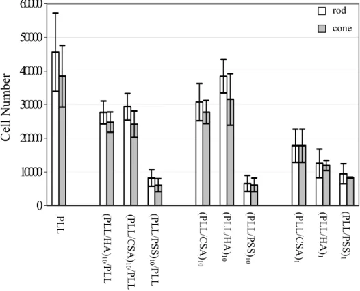
Figure 8. Rod and cone numbers after 48 h incubation on different polyelectrolyte films
composed of one and ten bilayers of PLL/CSA, PLL/HA, and PLL/PSS, and ending either as PLL or selected polyanions (CSA, HA or PSS). All results (n=4) are expressed as mean ± standard deviation (SD). Statistical comparisons were performed using student t test and p values < 0.05 were considered statistically significant.
Evaluation of the number of each cell type (rods and cones) on glass slides coated with multilayers was determined by counting the cells after specific immunostaining (Figure 8). In
vivo, the two different photoreceptor populations are surrounded by different 0 10000 20000 30000 40000 50000 60000 Cell N umbe r (PLL/CS A) 10 /P LL (PLL/ HA) 10 /PLL (PLL/P SS) 10 /P LL PLL (PLL/ HA) 10 (PLL/P SS) 10 (PLL/CS A) 10 (PLL/P SS) 1 (PLL/CS A) 1 (PLL/ HA) 1 rod cone
20
subcompartments of the IPM: rods are bathed in a soluble hyaluronan-rich matrix, cones are surrounded by chondroitin sulfate-rich structures.55 Thus we speculated that terminal surfaces ending either with HA or CSA might exhibit differences in rod or cone attachment. There was however no significant differences between the number of rods and cones attached. Among the different architectures, the highest number of photoreceptors attached was found for PLL1, (PLL/HA)10, and (PLL/CSA)10. The number of pairs of layers and the type of terminating layer had significant effects on the total number of photoreceptor cells attached. The number of photoreceptor cells attached to (PLL/PSS)10/PLL polyelectrolyte films was much less than that of (PLL/CSA)10/PLL and (PLL/HA)10/PLL multilayers. Viability assays and immunostaining data were basically similar (compare Figures 7 and 8), since PSS was the worst for photoreceptor numbers in both cases, and PLL was the best. There were slight differences between the two approaches which may be due to cell damage caused by handling.
The development of new strategies providing precise control of the microenvironment is of prime importance for regeneration and tissue engineering since ECM can affect cell behaviour in at least two ways. First, cell-ECM interaction may regulate cell functions through receptor-mediated signalling. Secondly, ECM can control the mobilization and presentation of growth and differentiation factors, thus modulating cell proliferation and controlling cell phenotype.23,67,68 The effects of different neurotrophic factors secreted from different retinal cells (glial cell-, RPE cell-, neuronal-derived) on cell survival and differentiation are being actively studied.61,62,69-72 Build-up of multilayered polyelectrolyte films could constitute a useful tool for the three-dimensional control of spatial or surface arrangement and composition of ECM analogs. The maintenance of biological activity of embedded proteins in the polyelectrolyte multilayers could allow to design biomaterials with tailored biological properties. We therefore added bFGF and IPM on top, or one bilayer beneath the film surface to mimic ECM.
21
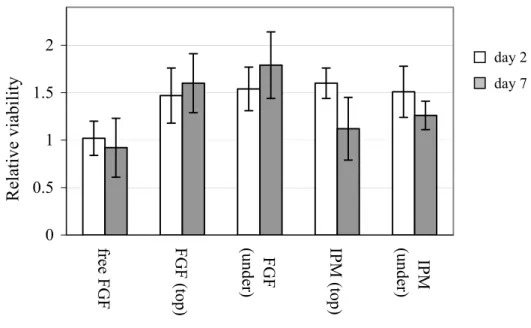
Figure 9. Effect of bFGF and IPM on survival of photoreceptor cells. The photoreceptor cells
were seeded onto (PLL/CSA)10/PLL multilayers built up on glass slides and bFGF or IPM were either added to the media (“free bFGF”), adsorbed to the film surface [“FGF (top)” or “IPM (top)” respectively], or adsorbed to the surface which was then coated with one additional bilayer of PLL/CSA [“bFGF (under)” or “IPM (under)” respectively]. The OD values were normalized for each incubation time by comparison to OD values obtained for photoreceptor cells on (PLL/CSA)10/PLL polyelectrolyte multilayers (controls).
The relative viability of photoreceptor cells at days 2 and 7 was determined by MTT tests and OD measurements obtained for (PLL/CSA)10/PLL polyelectrolyte multilayers (Figure 9). In accordance with the literature61 bFGF supplementation in the medium did not increase the survival rate relative to controls after 7 days in vitro. The survival promoting effect of free bFGF could be observed when cells were incubated for longer periods (data not shown). However, adsorption of bFGF either on top or beneath a terminal bilayer resulted in statistically significant increases in survival compared to controls and also to free bFGF at days 2 and 7 (p<0.05). The reasons for differences between photoreceptor cells supplemented with free and adsorbed bFGF could be multiple. For example, local concentration of bFGF at the film surface could be larger than in bulk solution. Moreover the direct binding of growth factors to PLL might also affect biological activity, since protein folding may be different when bFGF is attached to a solid substrate, optimising its presentation to cell membrane receptors. It should be noted that bFGF is usually attached to a matrix or carrier molecules,
0 0.5 1 1.5 2 free F G F
FGF (top) (under) FGF IPM
(top) IPM (under) Re la tive via bility day 2 day 7
22
such as basement membrane, proteoglycan or soluble receptor.55 Matrix-dependent enhancement of growth factor effects has been previously demonstrated by Ma et al.73, who observed that FGFs incorporated in a collagen layer immobilized on PLLA surfaces further stimulated chondrocyte cell growth.
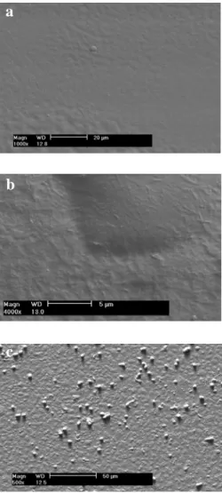
Stability of the differentiated cell state is crucial for functionality of the construction to be transplanted. The effect of supplementation with free bFGF, and adsorbed bFGF or the insoluble fraction of IPM on top and within the polyelectrolyte substrate, on expression of photoreceptor-specific markers was also studied (Figures 10 and 11). The glass slides coated with polyelectrolyte films only were visualized as smooth surfaces by SEM (Figure 10a), whereas presence of the insoluble fraction of IPM was seen in the form of fibrils (Figure 10b).56,74 Photoreceptor cells on IPM absorbed polyelectrolyte films are shown in Figure 10c.
23
Figure 10. Scanning electron micrographs (SEM) of (PLL/CSA)10/PLL bilayers a) before, b)
after IPM adsorption and c) 48 h after photoreceptor cell seeding.
a
b
c
24 0 10000 20000 30000 40000 50000 C ontr ol free FGF FG F ( top) FG F ( unde r) IP M ( top) IP M ( unde r) C one nu m be r
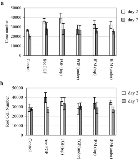
Figure 11. Effects of bFGF and IPM on the number of a) cones, b) rods at days 2 and 7. The
photoreceptor cells were seeded onto (PLL/CSA)10/PLL multilayers built up on glass slides and bFGF or IPM were either added to the media (“free bFGF”), adsorbed to the film surface [“FGF (top)” or “IPM (top)” respectively], or adsorbed to the surface which was then coated with one additional bilayer of PLL/CSA [“bFGF (under)” or “IPM (under)” respectively]. When cell numbers were scored after 2 days in vitro, there were greater numbers of immunolabeled cones in the presence of free bFGF and IPM absorbed on top (p<0.05) than on (PLL/CSA)10/PLL multilayers alone (Figure 11a, white bars). By contrast, except for free bFGF supplementation to the culture media, there were no statistical differences in rod cell numbers at this same time point (Figure 11b, white bars). When calculated as total photoreceptor numbers (rods plus cones), significant increases compared to control substrate were seen for all treatments except “bFGF under”. These increases were not always seen when survival was measured by viability assay (Figure 9), which may in part be due to immunolabelling of some dying cells in addition to viable ones. Although no statistical
a 0 10000 20000 30000 40000 50000 C ont ro l free FG F FGF(t op) FGF( unde r) IPM ( top) IPM (unde r) R od C el l Num be r day 2 day 7 day 2 day 7 b
25
differences for cone or rod cell numbers on modified film surfaces were observed on day 7 when evaluated separately (Figure 11), the total photoreceptor cell number (rod plus cones) seeded on bFGF adsorbed on top was found to be statistically higher than controls (p<0.05) (not shown). In general, the data indicate that bFGF has more effect on cone survival than that on rods under the present experimental conditions, which may be due to selective expression of specific FGF receptors on cones.75
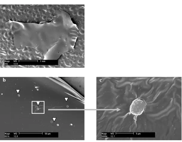
Preliminary detachment experiments of polyelectrolyte multilayer films from the glass slides were also undertaken. After the buildup of 60 bilayers of PLL/CSA, the film was crosslinked with carbodiimide/hydroxysuccinimide (EDC/NHS) for 12 hours as previously described.76 Detachment of the polyelectrolyte multilayer film was realized by immersion in an alkaline solution (NaOH 0.1 M) for 30 min. Polyelectrolyte films could often be detached from glass slides without breaking, but complete detachment was not always successful. Figure 12a constitutes an example of a piece of the detached multilayer as visualized by SEM. Following detachment, films were placed in 24 well culture wells and primary photoreceptor cells were seeded on top at an initial density of 1x10⁶ cells/film. As seen in Figures 12b and 12c, cell attachment on the detached film was very low. A more efficient method will be tested in the future using strategies of functionalized films to maximize photoreceptor cell adhesion. However this approach requires the availability of mechanically stable membranes to permit their recovery at the end of incubation. Preliminary tests performed with fragile films showed promising results for future studies on temporary self-standing templates for subretinal photoreceptor delivery.
26
Figure 12. Scanning electron micrographs (SEM) of a) piece of detached polyelectrolyte film
deposited on granular glue surface, b) photoreceptor cells seeded onto the detached film at an initial seeding density of 1x10⁶ cells/film, c) enlargement of a photoreceptor cell. Arrow heads represent the photoreceptor cells.
Conclusion
In this study, we assembled polyelectrolyte films using the layer-by-layer deposition method. Poly(L-lysine) (PLL) was used as a polycation, and chondroitin sulfate (CSA), poly(styrene sulfonate) (PSS) or hyaluronic acid (HA) as polyanions. These three different films composed of (PLL/CSA), (PLL/PSS) or (PLL/HA) exhibited an exponential growth regime, and the polyanion or polycation or both polyelectrolytes was/were able to diffuse throughout the entire multilayer depth. From the different systems evaluated, the highest numbers of photoreceptors attached were obtained for PLL1, (PLL/HA)10, followed by (PLL/CSA)10. PSS was found to be the least favourable terminating layer for photoreceptor cell viability. Functionalized polyelectrolyte multilayer films were obtained by adsorbing basic fibroblastic factor (bFGF) or the insoluble fraction of interphotoreceptor matrix (IPM) on or within the
a
b c
27
(PLL/CSA) polyelectrolyte multilayers. bFGF and IPM adsorption on top of the (PLL/CSA)10/PLL polyelectrolyte films increased the number of photoreceptor cells attached, and in particular bFGF adsorbed on the top led to a statistically significant increase in photoreceptor cell survival at day 7. This convenient and effective layer-by-layer method can be used to prepare bioactive membranes with extracellular matrix-like composition, for the purposes of functionalized tissue engineering. Such very thin films can be detached and exhibit the potential to deliver photoreceptor cells within the subretinal space and ensure a controlled laminar organization and maintenance of differentiation.
Acknowledgements
A.T. thanks the Scientific and Technical Research Council of Turkey for financial support through the “NATOB1 grant”. We thank Jérôme Mutterer (Institut de Biologie Moléculaire des Plantes, CNRS/ULP, Strasbourg, France) for his help with the CLSM. The CLSM platform used in this study was co-financed by the Région Alsace, the Université Louis Pasteur, and the Association pour la Recherche sur le Cancer. We also thank Nadia Messaddeq (Institut de Génétique et Biologie Moléculaire et Cellulaire, CNRS/ULP/INSERM, Illkirch, France) for her technical assistance with SEM.
References
(1) Delyfer, M. N.; Leveillard, T.; Mohand-Said, S.; Hicks, D.; Picaud, S.; Sahel, Biol.
Cell 2004, 96, 261-269.
(2) Bennett, J.; Zeng, Y.; Bajwa, R.; Klatt, L.; Li, Y.; Maguire, A. M. Gene Therapy
1998, 5, 1156-1164.
(3) D'Cruz, P. M.; Yasumura, D.; Weir, J.; Matthes, M. T.; Abderrahim, H.; LaVail, M. M.; Vollrath, D. Hum. Mol. Genet. 2000, 9, 645-651.
(4) McGee Sanftner, L. H.; Abel, H.; Hauswirth, W. W.; Flannery, J. G. Mol Ther 2001,
4, 622-629.
(5) Li, T.; Sandberg, M. A.; Pawlyk, B. S.; Rosner, B.; Hayes, K. C.; Dryja, T. P.; Berson, E. L. Proc. Natl. Acad. Sci. USA 1998, 95, 11933-11938.
(6) LaVail, M. M.; Yasumura, D.; Matthes, M. T.; Lau-Villacorta, C.; Unoki, K.; Sung, C. H.; Steinberg, R. H. Invest. Ophthalmol. Vis. Sci. 1998, 39, 592-602. (7) Frasson, M.; Picaud, S.; Leveillard, T.; Simonutti, M.; Mohand-Said, S.; Dreyfus,
H.; Hicks, D.; Sahel, J. Invest. Ophthalmol. Vis. Sci. 1999, 40, 2724-2734.
28
(8) Bok, D.; Yasumura, D.; Matthes, M. T.; Ruiz, A.; Duncan, J. L.; Chappelow, A. V.; Zolutukhin, S.; Hauswirth, W.; Lavail, M. M. Exp. Eye Res. 2002, 74, 719-735. (9) Kommonen, B.; Kylma, T.; Cohen, R. J.; Penn, J. S.; Paulin, L.; Hurwitz, M.;
Hurwitz, R. L. Ophthalmic Res. 1996, 28, 19-28. (10) Lee, K. S.; Tsien, R. W. Nature 1983, 302, 790-794. (11) Turner, J. E.; Blair, J. R. Brain Res. 1986, 391, 91-104.
(12) Mohand-Said, S.; Hicks, D.; Simonutti, M.; Tran-Minh, D.; Deudon-Combe, A.; Dreyfus, H.; Silverman, M. S.; Ogilvie, J. M.; Tenkova, T.; Sahel, J. Ophthalmic
Res. 1997, 29, 290-297.
(13) Ahmad, I.; Dooley, C. M.; Thoreson, W. B.; Rogers, J. A.; Afiat, S. Brain Res 1999,
831, 1-10.
(14) Chacko, D. M.; Rogers, J. A.; Turner, J. E.; Ahmad, I. Biochem. Biophys. Res.
Commun. 2000, 268, 842-846.
(15) Kicic, A.; Shen, W. Y.; Wilson, A. S.; Constable, I. J.; Robertson, T.; Rakoczy, P. E. J. Neurosci. 2003, 23, 7742-7749.
(16) Aramant, R.; Seiler, M.; Turner, J. E. Invest. Ophthalmol Vis. Sci. 1988, 29, 498-503. (17) Seiler, M. J.; Aramant, R. B. Invest. Ophthalmol Vis. Sci. 1998, 39, 2121-2131. (18) Silverman, M. S.; Hughes, S. E. Invest. Ophthalmol Vis. Sci. 1989, 30, 1684-1690. (19) Tomita, M.; Adachi, Y.; Yamada, H.; Takahashi, K.; Kiuchi, K.; Oyaizu, H.;
Ikebukuro, K.; Kaneda, H.; Matsumura, M.; Ikehara, S. Stem Cells 2002, 20, 279-283.
(20) Lavik, E. B.; Klassen, H.; Warfvinge, K.; Langer, R.; Young, M. J. Biomaterials
2005, 26, 3187-3196.
(21) Ingber, D. E. Ed. Eugene Bell, Birkhauser, Boston, Basel, Berlin 1993, 3-19.
(22) Rosso, F.; Giordano, A.; Barbarisi, M.; Barbarisi, A. J. Cell Physiol. 2004, 199, 174-180.
(23) Lutolf, M. P.; Hubbell, J. A. Nat. Biotechnol. 2005, 23, 47-55.
(24) Hageman, G. S.; Johnson, L. V. Progress Ret. Res. 1991, 10, 208-249. (25) Hollyfield, J. G. Invest. Ophthalmol. Vis. Sci. 1999, 40, 2767-2769.
(26) Hageman, G. S.; Kirchoff-Rempe, M. A.; Lewis, G. P.; Fisher, S. K.; Anderson, D. H. Proc. Natl. Acad. Sci. USA 1991, 88, 6706-6710.
(27) Becerra, S. P.; Fariss, R. N.; Wu, Y. Q.; Montuenga, L. M.; Wong, P.; Pfeffer, B. A.
Exp. Eye Res. 2004, 78, 223-234.
(28) Decher, G.; Hong, J. D.; Schmitt, J. Thin Solid Films 1992, 210, 831-835.
29
(29) Decher, G. Science 1997, 277, 1232-1237.
(30) Ladam, G.; Schaad, P.; Voegel, J.-C.; Schaaf, P.; Decher, G.; Cuisinier, F.
Langmuir 2000, 16, 1249-1255.
(31) Zhu, Y. B.; Gao, C. Y.; He, T.; Liu, X. Y.; Shen, J. C. Biomacromolecules 2003, 4, 446-452.
(32) Jessel, N.; Atalar, F.; Lavalle, P.; Mutterer, J.; Decher, G.; Schaaf, P.; Voegel, J.-C.; Ogier, J. Adv. Mater. 2003, 15, 692-695.
(33) Zhang, J.; Senger, B.; Vautier, D.; Picart, C.; Schaaf, P.; Voegel, J.-C.; Lavalle, P.
Biomaterials 2005, 26, 3353-3361.
(34) Elbert, D. L.; Herbert, C. B.; Hubbell, J. A. Langmuir 1999, 15, 5355-5362. (35) Picart, C.; Lavalle, P.; Hubert, P.; Cuisinier, F. J. G.; Decher, G.; Schaaf, P.;
Voegel, J.-C. Langmuir 2001, 17, 7414-7424.
(36) Picart, C.; Mutterer, J.; Richert, L.; Luo, Y.; Prestwich, G. D.; Schaaf, P.; Voegel, J.-C.; Lavalle, P. Proc. Natl. Acad. Sci. USA 2002, 99, 12531-12535.
(37) Richert, L.; Lavalle, P.; Payan, E.; Zheng, X. S.; Prestwich, G. D.; Stoltz, J. F.; Schaaf, P.; Voegel, J.-C.; Picart, C. Langmuir 2004, 20, 448-458.
(38) Lavalle, P.; Vivet, V.; Jessel, N.; Decher, G.; Mesini, P. J.; Voegel, J.-C.; Schaaf, P. Macromolecules 2004, 37, 1159-1162.
(39) Boulmedais, F.; Ball, V.; Schwinte, P.; Frisch, B.; Schaaf, P.; Voegel, J.-C.
Langmuir 2003, 19, 440-445.
(40) Boulmedais, F.; Bozonnet, M.; Schwinté, P.; Voegel, J.-C.; Schaaf, P. Langmuir
2003, 19, 9873-9882.
(41) Boura, C.; Menu, P.; Payan, E.; Picart, C.; Voegel, J.-C.; Muller, S.; Stoltz, J. F.
Biomaterials 2003, 24, 3521-3530.
(42) Mendelsohn, J. D.; Yang, S. Y.; Hiller, J.; Hochbaum, A. I.; Rubner, M. F.
Biomacromolecules 2003, 4, 96-106.
(43) Richert, L.; Boulmedais, F.; Lavalle, P.; Mutterer, J.; Ferreux, E.; Decher, G.; Schaaf, P.; Voegel, J.-C.; Picart, C. Biomacromolecules 2004, 5, 284-294. (44) Zhu, H.; Ji, J.; Shen, J. Biomaterials 2004, 25, 109-117.
(45) Salloum, D. S.; Schlenoff, J. B. Biomacromolecules 2004, 5, 1089-1096.
(46) Caruso, F.; Niikura, K.; Furlong, D. N.; Okahata, Y. Langmuir 1997, 13, 3427-3433. (47) Lvov, Y.; Ariga, K.; Ichinose, I.; Kunitake, T. J. Am. Chem. Soc. 1995, 117,
6117-6123.
30
(48) Chluba, J.; Voegel, J.-C.; Decher, G.; Erbacher, P.; Schaaf, P.; Ogier, J.
Biomacromolecules 2001, 2, 800-805.
(49) Derbal, L.; Lesot, H.; Voegel, J.-C.; Ball, V. Biomacromolecules 2003, 4, 1255-1263.
(50) Jessel, N.; Lavalle, P.; Meyer, F.; Audouin, F.; Frisch, B.; Schaaf, P.; Ogier, J.; Decher, G.; Voegel, J.-C. Adv. Mater. 2004, 16, 1507-1511.
(51) Seal, B. L.; Otero, T. C.; Panitch, A. Mat. Sci. Eng. R 2001, 34, 147-230.
(52) Thierry, B.; Winnik, F. M.; Merhi, Y.; Tabrizian, M. J. Am. Chem. Soc. 2003, 125, 7494-7495.
(53) Burke, S. E.; Barrett, C. J. Biomacromolecules 2003, 4, 1773-1783.
(54) Thierry, B.; Winnik, F. M.; Merhi, Y.; Silver, J.; Tabrizian, M. Biomacromolecules
2003, 4, 1564-1571.
(55) Khademhosseini, A.; Suh, K. Y.; Yang, J. M.; Eng, G.; Yeh, J.; Levenberg, S.; Langer, R. Biomaterials 2004, 25, 3583-3592.
(56) Barbucci, R.; Magnani, A.; Lamponi, S.; Pasqui, D.; Bryan, S. Biomaterials 2003,
24, 915-926.
(57) Sauerbrey, G. Z. Phys. 1959, 155, 206-222.
(58) Tiefenthaler, K.; Lukosz, W. J. Opt. Soc. Am. B 1989, 6, 209-220.
(59) Voros, J.; Ramsden, J. J.; Csucs, G.; Szendro, I.; De Paul, S. M.; Textor, M.; Spencer, N. D. Biomaterials 2002, 23, 3699-3710.
(60) Picart, C.; Ladam, G.; Senger, B.; Voegel, J.-C.; Schaaf, P.; Cuisinier, F. J. G.; Gergely, C. J. Chem. Phys. 2001, 115, 1086-1094.
(61) Traverso, V.; Kinkl, N.; Grimm, L.; Sahel, J.; Hicks, D. Invest. Ophthalmol. Vis. Sci.
2003, 44, 4550-4558.
(62) Fintz, A. C.; Audo, I.; Hicks, D.; Mohand-Said, S.; Leveillard, T.; Sahel, J. Invest.
Ophthalmol Vis. Sci. 2003, 44, 818-825.
(63) Lavalle, P.; Picart, C.; Mutterer, J.; Gergely, C.; Reiss, H.; Voegel, J.-C.; Senger, B.; Schaaf, P. J. Phys. Chem. B 2004, 108, 636-648.
(64) Tryoen-Toth, P.; Vautier, D.; Haikel, Y.; Voegel, J.-C.; Schaaf, P.; Chluba, J.; Ogier, J. J. Biomed. Mater. Res. 2002, 60, 657-667.
(65) Vautier, D.; Karsten, V.; Egles, C.; Chluba, J.; Schaaf, P.; Voegel, J.-C.; Ogier, J.
J. Biomat. Sci.-Polym. Ed. 2002, 13, 713-732.
(66) Salloum, D. S.; Olenych, S. G.; Keller, T. C. S.; Schlenoff, J. B. Biomacromolecules
2005, 6, 161-167.
31
(67) Taipale, J.; Keski-Oja, J. Faseb J 1997, 11, 51-59.
(68) Brodkin, K. R.; Garcia, A. J.; Levenston, M. E. Biomaterials 2004, 25, 5929-5938. (69) Gaur, V. P.; Liu, Y.; Turner, J. E. Exp Eye Res 1992, 54, 645-659.
(70) Cao, W.; Wen, R.; Li, F.; Cheng, T.; Steinberg, R. H. Invest. Ophthalmol Vis. Sci.
1997, 38, 1358-1366.
(71) Sheedlo, H. J.; Nelson, T. H.; Lin, N.; Rogers, T. A.; Roque, R. S.; Turner, J. E.
Brain Res. Dev. Brain Res. 1998, 107, 57-69.
(72) Li, A.; Lane, W. S.; Johnson, L. V.; Chader, G. J.; Tombran-Tink, J. J. Neurosci.
1995, 15, 385-393.
(73) Ma, Z.; Gao, C.; Gong, Y.; Shen, J. Biomaterials 2005, 26, 1253-1259.
(74) Hollyfield, J. G.; Rayborn, M. E.; Landers, R. A.; Myers, K. M. Exp. Eye Res. 1990,
51, 107-110.
(75) Kinkl, N.; Hageman, G. S.; Sahel, J. A.; Hicks, D. Mol. Vis. 2002, 8, 149-160. (76) Lavalle, P.; Boulmedais, F.; Ball, V.; Mutterer, J.; Schaaf, P.; Voegel, J.-C. J.
Membr. Sci. 2005, 253, 49-56.