Development of Technical Bases for Using Infrared Thermography
for Nondestructive Evaluation of Fiber Reinforced Polymer
Composites Bonded to Concrete
byM6nica Anastasia Starnes
Bachelor of Science in Civil Engineering
University of New Mexico, Albuquerque, New Mexico, 1997 Master of Science in Civil Engineering
University of New Mexico, Albuquerque, New Mexico, 1998
Submitted to the Department of Civil and Environmental Engineering in partial fulfillment of the requirements for the
Degree of Doctor of Philosophy in Structures and Materials at the
MASSACHUSETTS INSTITUTE OF TECHNOLOGY September 2002
A u th o r ... ... . ... ... ...
Department of Civil and Environmental Engineering August 16, 2002 //
C ertified b y .. ...
Eduardo Kausel, Professor of Civil and Environmental Engineering Department of Civil and Environmental Engineering
Accepte
Oral Buyukozturk, Chairman SASSACHUSETTS INSTITUTE Departmental Committee on Graduate Studies
Development of Technical Bases for Using Infrared Thermography for
Nondestructive Evaluation of Fiber Reinforced Polymer Composites Bonded
to Concrete
by
M6nica Anastasia Starnes
Submitted to the Department of Civil and Environmental Engineering on August 16, 2002 in partial fulfillment of the requirements for the
Degree of Doctor of Philosophy in Structures and Materials
Abstract
Fiber-reinforced polymer (FRP) composites, in the form of pultruded laminates or built-up woven fabrics, are being used widely to strengthen existing concrete and masonry structures. The success of these materials in performing their intended functions depends, to a large extent, on how well they are bonded to themselves and to the substrate. There is a need for an efficient and reliable method to detect and characterize defects at the substrate interface and within multi-ply systems. Infrared thermography is well suited for this purpose because it is inherently sensitive to the presence of near-surface defects and can interrogate large areas efficiently. Before infrared thermography can be developed into a standard methodology, however, an understanding is needed of the effects of testing parameters and different types of defects. This dissertation focuses on establishing the potential for quantitative infrared thermography, that is, not only detecting but also characterizing subsurface flaws. Numerical and experimental methods are used to investigate the effectiveness of infrared thermography to estimate the width of subsurface flaws in fiber-reinforced polymer laminates bonded to concrete.
First, a dimensional analysis of a simplified case of one-dimensional heat diffusion in an infinite half space is performed to establish the parameters that affect the thermal response of the test object. The results from the dimensional analysis identified the factors that had to be investigated in the parametric study.
Next, the finite-element method is used to carry out parametric analyses of the thermal response of simulated defects in fiber-reinforced polymer laminates applied to a concrete substrate. In this study, a "defect" is an air gap between laminates, at the laminate/substrate interface, or in the substrate. The aim is to assess the potential for quantitative infrared thermography in not only detecting a flaw but also being able to describe its physical characteristics. Six parametric studies are presented, namely: 1) relationships between the thermal input, the maximum signal, and the maximum surface temperature; 2) effect of thermal material properties of FRP composites and concrete; 3) effects of flaw depth and the number of FRP layers; 4) effect of flaw thickness; 5) effect of flaw width and estimation of flaw width; and 6) a multi-parameter screening study to determine relevant factors. From these simulations, procedures are established for selecting the thermal input and estimating the flaw depth and width.
The third component of the investigation focuses on laboratory studies. Controlled-flaw experiments are performed to evaluate the potential of infrared thermography testing to quantitatively assess subsurface flaw in FRP bonded to concrete. First, a qualitative test is successfully performed to evaluate the potential for detection of each simulated flaw embedded in the test object. The next two experiments involve quantitative thermography testing of an air void embedded at the interface between a pultruded FRP laminate and the concrete substrate. A comparison between the quantitative infrared thermography test and finite-element simulations of the same test is also performed. Good agreement between experimental thermal response parameters and those calculated from finite-element models provides assurance of the validity of parametric studies based on numerical simulations. Controlled-flaw experiments are also performed to verify the procedure for estimating the width of subsurface flaws. Good agreement is found between the estimated and actual flaw dimensions. Data smoothing is shown to be effective in removing "noise" from measured temperature profiles. An experimental screening experiment is carried out to determine the relevant factors affecting the thermal response of the controlled-flaw specimens. The results indicate that the depth of the flaw is the only relevant factor affecting the time to maximum signal. Finally, an experiment is performed to determine the degree of repeatability of infrared thermography testing and the assessment of adequate sampling rate. It is concluded that sampling rates of 1 Hz are adequate for quantitative evaluation of FRP bonded to concrete.
The results of investigation provide demonstrable evidence of the potential of infrared thermography to characterize the depth and width of flaws (air voids) embedded in FRP composites bonded to concrete.
Thesis supervisor: Eduardo Kausel
Acknowledgements
I would like to express my most sincere admiration and gratefulness to my doctoral advisor, Professor Eduardo Kausel. I will always be deeply thankful for his continuing guidance, mentorship, and encouragement.
I also want to express my deep admiration to Dr. Nicholas Carino, my advisor at the National Institute of Standards and Technology (NIST). His encouragement for seeking scientific and engineering discovery will always be with me.
I would also like to express my gratitude to the remaining members of my committee: Dr. Jerome Connor, Dr. Oral Buyukozturk, and Dr. Shi-Chang Wooh. Their support and guidance is greatly appreciated.
I am deeply thankful to the National Science Foundation. Its support through the Graduate Research Fellowship has allowed me to pursue my goals for advanced learning.
I would also want to thank NIST and, specially, the Building and Fire Research Laboratory for funding my investigation during the last two years. While at NIST, I have had the great pleasure of collaborating with the some of the most distinguished and innovative engineers and researchers in the country. I am greatly thankful to my colleagues at NIST's Structures Division, especially Dr. John Gross and Dr. H.S Lew, for their enduring technical help and friendship. I also want to express thanks to Mr. Andre Witcher, of the Structures Division, for his help with the fabrication of the experimental apparatus, and to Dr. Daniel Flynn and Dr. William Healy, of the Building Environment Division, for their help and lessons in the field of heat transfer.
Finally, I would like to profoundly thank my family and friends for their support through the years. Their support, encouragement, and patience have always allowed me to fulfill my goals.
Table of Contents C hapter 1 Introduction... 11 1.1 Background ... 11 1.2 M otivation...13 1.3 Research Objectives... 17 1.4 Research Approach ... 17 1.5 Outline of Thesis...17
C hapter 2 Literature R eview ... 19
2.1 Introduction...19
2.2 Theoretical Principles ... 19
2.3 Literature Review ... 23
2.3.1 Close-Form Versus Numerical Analytical Studies ... 23
2.3.2 Sum m ary of Investigations ... 24
2.3.2a M aterial Properties... 24
2.3.2b D efect Characteristics ... 25
2.3.2c Therm al Input... 28
2.3.2d Observation Tim e... 29
2.3.2e Testing M ode ... 29
2.3.2f A dditional Considerations ... 30
2.3.3 Sim ulation Outputs V ersus Experim ental D ata... 31
2.4 Sum m ary...31
Chapter 3 D im ensional A nalysis... 33
3.1 Introduction...33
3.2 Dim ensional Analysis ... 33
3.3 Sum m ary...37
Chapter 4 Param etric Studies... 39
4.1 Introduction...39
4.2 Single-Factor Param etric Study ... 40
4.3 Param etric Study N o.1: Effect of Therm al Input... 40
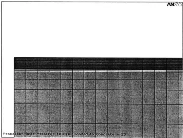
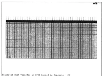
4.3.1 2-D M odels ... 41
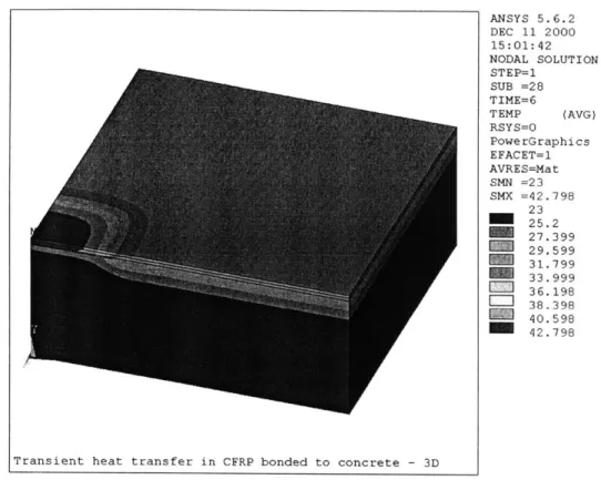
4.3.2 3-D M odels ... 44
4.3.3 Therm al Loading and Boundary Conditions... 45
4.3.4 Results...49
4.3.5 Sum m ary...65
4.4 Parametric Study No. 2: Effect of Thermal Material Properties ... 66
4.4.2 M aterial Properties... 67
4.4.3 Therm al Loading and Boundary Conditions... 69
4.4.4 Result ... 70
4.4.4a Effect of the Therm al Conductivity of FRP... 70
4.4.4b Effect of the Specific Heat of FRP ... 77
4.4.4c Effect of the Thermal Conductivity of Concrete ... 81
4.4.4d Effect of the Specific Heat of Concrete ... 83
4.4.4e Combined Effects of Changes in FRP and Concrete Properties...85
4.4.5 Sum m ary...86
4.5 Parametric Study No.3: Effect of the Depth of the Flaw... 87
4.5.1 G eom etry of M odel... 88
4.5.2 M aterial Properties... 92
4.5.3 Therm al Loading and Boundary Conditions... 93
4.5.4 Results...93
4.5.4a D ebonds ... 93
4.5.4b D elam inations ... 96
4.5.4c Concrete Spalls ... 99
4.5.4d Estim ation of D epth ... 108
4.5.5 Sum m ary...112
4.6 Parametric Study No.4: Effect of the Thickness of the Flaw ... 113
4.6.1 G eom etry of M odel...113
4.6.2 M aterial Properties...116
4.6.3 Therm al Loading and Boundary Conditions...116
4.6.4 Results...117
4.6.4a D elam inations ... 117
4.6.4b D ebonds ... 121
4.6.4c Concrete Spalls ... 127
4.6.4d M inim um Flaw Thickness ... 131
4.6.5 Sum m ary...133
4.7 Parametric Study No.5: Effect of the Width of the Flaw and Estimation of W idth of the Flaw ... 134
4.7.1 G eom etry of M odel...134
4.7.2 M aterial Properties...136
4.7.3 Therm al Loading and Boundary Conditions...136
4.7.4 R esults...137
4.7.4a D elam inations ... 137
4.7.4b D ebonds ... 143
4.7.4c Concrete Spalls ... 149
4.7.4d Com parison of W idth Estim ations...155
4.7.5 Sum m ary...159
4.8 Sum m ary of Single-Factor Param etric Studies...160
4.9 M ulti-Factor Param etric Study ... 161
4.9.1 D esign of Screening Experim ent ... 161
4.9.2 N um erical Sim ulations...164
4.9.3 FEM O utput ... 164
4.9.5 Conclusions for t...168
4.9.6 Analysis of Results for ATax... ... ... ... 168
4.9.7 Conclusions for ATax...172
4.9.8 Analysis of Results for T.ax... .. .. ... 172
4.9.9 Conclusions for T.ax ... 175
4.9.10 Summary of the M ulti-Factor Parametric Study...175
4.10 Summary...175
Chapter 5 Laboratory Studies ... 177
5.1 Introduction...177
5.2 Design of Experiments...178
5.3 Testing Configurations...180
5.3.1 Qualitative Test...181
5.3.2 Quantitative Test...182
5.3.2a Heat Sources ... 182
5.3.2c Infrared Cameras...183
5.3.2c Data Acquisition and Analysis Software ... 184
5.3.3 Specimens ... 184
5.3.3a Specimens Fabricated with Pultruded CFRP Laminates ... 184
5.3.3b Specimens Fabricated with Wet Lay-Up CFRP Laminates...186
5.4 Experiment #1: Qualitative Test ... 191
5.5 Experiment #2: Comparison of IR Thermography and FEM Simulations ... 192
5.5.1 Determination of Surface Emissivity of Pultruded FRP...193
5.5.2 Determination of Heat Flux ... 195
5.5.2a Homogeneity of Heat Flux...195
5.5.2b Heat Flux as a Function of Time...198
5.5.3 IR Thermography Test Procedure and Analysis...199
5.5.4 Verification of FEM Simulations...201
5.5.4a Simulation M odels...201
5.5.4b Results...203
5.5.5 Conclusions of the Comparison of IR Thermography and FEM Simulations ... 204
5.6 Experiment #3: Estimation of Flaw W idth...205
5.6.1 Test Procedure ... 205
5.6.2 Data Analysis ... 205
5.6.3 Conclusions of the Estimation of Flaw W idth...209
5.7 Experiment #4: Screening Experiment ... 209
5.7.1 Determination of Surface Emissivity of W et Lay-Up FRP ... 209
5.7.2 Determination of Heat Flux ... 212
5.7.3 Test Procedure ... 214
5.7.4 Data Analysis ... 215
5.7.4a Analysis of Individual Tests ... 215
5.7.4b Analysis of Full Factorial Screening Experiments ... 217
5.7.4c Analysis of Results for ts...218
5.7.4d Analysis of Results for t. ... 224
5.8 Experiment #5: Investigation of Test Repeatability and Effect of Sampling Rate...229
5.8.1 D eterm ination of H eat Flux ... 230
5.8.2 Test Procedure ... 232
5.8.3y ... 232
5.8.4 Conclusions of the Investigation of Test Repeatability and Effect of Sam pling Rate...242
5.9 Conclusions of Laboratory Studies...242
Chapter 6 Discussion...245 6.1 Sum m ary...245 6.1.1 Introduction...245 6.1.2 Research Objective ... 246 6.1.3 Approach...246 6.2 Conclusions...247 6.2.1 D im ensional Analysis ... 247
6.2.2 Param etric Studies ... 247
6.2.3 Laboratory Studies ... 249
6.2.4 Sum m ary...250
6.2.5 Research Lim itations ... 250
6.3 Future Im plications ... 251
Chapter
1
Introduction
1.1
Background
The trend in civil engineering is toward the development of high-performance structures that incorporate advanced materials. Moreover, the up front application of advanced materials in civil engineering structures incorporates the use of fiber composites. Fiber-reinforced polymer (FRP) composites are two-phase engineered materials that combine high performance fibers within a polymer matrix. Typically, FRP composites are reinforced by long unidirectional continuous fibers. These advanced materials are characterized by their high strength, high stiffness, low density, and durability. Consequently, wide application of advanced composites may allow engineers to design innovative structures.
Most FRP materials are generally used as thin elements or structural subsystems. In civil engineering applications, FRP composites are undertaking a major role in the rehabilitation of existing civil infrastructure. Rehabilitation involves the repair and strengthening of functional or structural deficiencies of structural components. For this purpose, composite layers or laminates are primarily bonded to existing reinforced concrete and masonry structures using adhesives such as epoxy resins. The primary purpose of bonded FRP composites is to enhance the structural capacity of the rehabilitated structure.
However, the major factor that contributes to the optimum performance of the composite system is the quality of bond between the FRP and the concrete or masonry substrate. For example, in beam and wall applications, fabricators must be able to guarantee bond and sufficient development length and anchorage of the FRP laminates. Yet, standard quality control procedures to assess the integrity of FRP composite systems still need to be developed for civil engineering applications. Ultimately, quality control of the final product is a requirement for the successful implementation of any new material in structural engineering systems.
Furthermore, the final mechanical properties of FRP composites are affected by environmental aspects such as temperature, moisture, and contaminants. As such, the quality of a FRP composite is influenced by the manufacturing process and where (factory vs. in situ) the composite is fabricated. For civil structures, installation and curing of FRP composites occur typically in the field rather than in a controlled environment. Generally, installation involves manual application of fabric and resins. Thus, there is potential for high variability of the final product unless appropriate quality control procedures are used. Composite thickness,
interlaminar adhesion, and substrate bonding must be carefully monitored. Additional defects intrinsic to this process are air voids and contaminants, which may accelerate the formation of in-service delaminations and debonds in the FRP composite.
A variety of techniques exist for installation of external FRP composite systems. The most common techniques in civil engineering applications are wet lay-up, prepreg, precured shells, resins infusion, and pultruded sheet. Figure 1.1 illustrates some of the applications of FRP composites for rehabilitation of civil engineering structures.
Column wrapping using wet lay-up
Beam reinforcement using pultruded sheet
Column wrapping using precured shell
Wall reinforcement using prepregs
Fig. 1.1 Examples of applications of FRP composites for rehabilitation purposes
Lay-up using fabric, tape, or tow is probably the most used technique (Karbhari et al., 1998). The installation process is simple: fiber fabric or tow is wrapped or wound around the structural member; resin is then impregnated using a wet bath. The primary advantages of this technique are that it provides the maximum flexibility for installation and is economical. Because installation involves manual application of fabric and resins, variability of the final product is to be expected. Air voids and contaminants are defects intrinsic to this process.
element. Although, generally more expensive than wet lay-up systems, prepreg systems are more consistent and have fewer defects. Additionally, prepregs need high curing temperatures, which produce higher glass transition temperature of their matrices. Despite the benefits of using prepregs, researchers claim that the application of these composites to masonry walls may be difficult due to the inherent stiffness of the plies (Christensen et al., 1996).
Precured shells are manufactured in a factory and then bonded in the field. The primary application of these jackets is for retrofitting of columns. The controlled fabrication process assures the quality of the FRP shell. However, adequate bonding of the shell to itself and to the concrete structure is critical.
The resin infusion process is a recently developed installation method. Dry fibers are first applied to the structure (primarily columns) and then followed by infusion of resin using a vacuum. Resin infusion systems are cured at ambient temperatures. Low glass transition temperature is a disadvantage. This technique achieves higher uniformity in the composite than wet lay-up.
Finally, the pultrusion manufacturing method allows fabrication of continuous cross sectional components (rods, laminates, channels, etc.). They are manufactured at the factory and externally bonded to the concrete structure in the field. Pultruded composites are mostly used in beam applications where thin strips are bonded to the tensile faces. Due to the high quality control at the factory, these FRP systems posses high uniformity and a minimum amount of defects within the composite but they must still be bonded to the structure in situ.
1.2
Motivation
FRP composites bonded to concrete are, by their nature and installation method, prone to high variability of thickness and other internal anomalies. Effective quality control methods for these composite systems must provide quantitative information regarding the thickness and fiber content of the applied composite and amount, location, and size of defects at any given time through the life of the structure. In addition, FRP composites are starting to be widely used without a complete understanding of the structural mechanics and durability properties of these materials. The inherent danger of erroneous expectations about the capabilities of FRP composites is an incentive for the development of reliable nondestructive evaluation techniques. Nondestructive testing (NDT) methods together with mechanics and durability studies should be able to predict structural reliability and material integrity and thus, allowing for the prioritization of the repair cycle of civil infrastructure.
Nondestructive testing techniques for FRP composites are already widely researched and used in the aerospace industry for both manufacturing quality control and routine maintenance inspection. Yet, the quality of the manufacturing process, sizes of the structures, boundary and environmental conditions, and available budget for inspection of aerospace structures are quite different from those of civil structures. Thus quality control of composite materials used in civil engineering applications requires the development of reliable NDT techniques and standard test methods for this particular application.
Nondestructive testing techniques can be categorized into two major groups: electromagnetic methods and mechanical vibration methods. Likewise, electromagnetic methods are subdivided
into nuclear, radar, thermography, magnetic, and electric. Mechanical vibration methods include ultrasonics, acoustic emissions, acousto-ultrasonics, vibration methods, and coin tap testing. Nuclear NDT methods such as radiography (X-rays) are of very limited use in the inspection of fiber reinforced polymers. The method has been tried for the determination of structure composition, density, permeability, thickness, fiber volume ratio, and moisture content, among others. The method does not detect interlaminar defects such as voids, debonds, and delaminations. The primary reason why interlaminar defects are not detected is that most flaws are perpendicular to the X-ray beam making detection nearly impossible. Debonds can not be detected because the absorption of the adherent is generally very high. The only solution for optimum inspection is the introduction of radio-opaque penetrants. However, penetrants require surface breaking and are highly toxic.
The bases for radar testing are very simple. A beam of electromagnetic energy is sent to the tested structure. Portions of the energy are transmitted through the structure but the remaining energy is reflected back from each boundary (surface, layer, or flaw) encountered. An example of radar methodology is short-pulse radar, which uses microwave energy. This method is used for the evaluation of delaminations and water content in concrete. Additionally, thickness, density, fiber orientation, volume ratio, material degradation, and flaws of FRP composites can be inspected using short-pulse radar. However, radar technology needs further improvements in antenna resolution for its application to FRP composites bonded to concrete structures.
Thermographic techniques (infrared thermography, liquid crystal thermography, etc.) consist in applying heat to the structure and observing the temperature gradients on the surface of the specimen. Infrared thermography is best suited for detection of anomalies near the surface of the specimen. Thus, detection of internal anomalies in thin FRP composites bonded to concrete is possible. In civil applications, current infrared thermography testing of FRP composites is focused on qualitative estimates of the state of the structure. The reason for the qualitative nature of the results is the complex relationship between the variables affecting the thermal response of the bonded assemblies.
Three examples of magnetic testing are magnetic induction, flux-leakage method, and nuclear magnetic resonance or magnetic resonance imaging (MRI). Both magnetic induction and flux-leakage testing are only effective for ferrous materials. Thus, testing of FRP composites is unfeasible. Nuclear magnetic resonance is widely used in other fields such as medicine. Only small specimens can be tested in a lab environment, hence making this method irrelevant to civil engineering applications.
Eddy-current is the most popular electric technique for testing FRP composites. Two basic methods are used on the determination of stacking sequence: resistive eddy-current path and resistive capacitive eddy-current path. On the resistive eddy-current path technique, the electric current passes from one fiber to another at the points of contact. On the other hand, the resistive capacitive eddy-current path method allows for an interfiber capacitive path in addition to the resistive path. Since the method requires a conductive material, glass fiber reinforced polymers cannot be tested. This method can determine the stacking sequence in carbon fiber reinforced polymers (CFRP). Eddy-current is also limited to composites with high fiber-volume ratio. An additional disadvantage is that eddy-current methods are insensitive to porosity, delaminations, and other nonconductive inclusions in the material.
Ultrasound techniques such as pulse echo, impulse echo, impulse response, surface waves, and plate wave method are widely used in civil engineering inspections. In this technique, a stress pulse is introduced to the surface using a transmitter. After the introduction of the pulse, a series of compression waves develop through the depth of the specimen. Waves are reflected to the surface by cracks or ply interfaces giving quantifiable data about the state of the material. Currently pulse echo is the most successful ultrasonics methods for testing composite materials in aerospace applications. Pulse echo techniques can determine the depth of FRP composites and their elastic modulus. However, due to the high attenuation of FRP composites, only low frequencies can be used to test these materials. This is a problem because most available T/R transducers are designed for higher frequencies.
Acoustic emission testing records elastic stress waves generated by localized cracking in the structure. Analysis of the wave propagation gives the extent of damage of the structural member. Although the method is widely used in lab and factory settings, field use is limited. The primary reason for this limitation is the high occurrence of noise contamination in civil engineering applications. Acousto-ultrasonic methods are very similar to ultrasonic techniques. They provide, however, information that is more detailed.
Dynamic or vibration methods include techniques such as resonant frequency, pulse velocity, and lamb-wave methods. The resonant frequency method evaluates the dynamic modulus of the structure using its fundamental frequency. This technique requires a transducer to be acoustically coupled to the test object using a liquid couplant. The structure or test object directly affects the resonance frequency and signal amplitude of the transducer. The transducer, which usually operates in the 25 Hz to 500 Hz band, produces a specific standing wave in the test object. The presence of an internal flaw changes the pattern in the standing wave of the material. Although very successful in aerospace structures, this method is limited to laboratory size specimens. The primary reason for the small specimen size is that small defects have little effect on the natural frequency of the structure (i.e. large civil structure). Therefore, resonance testing is usually conducted on individual structural components to detect localized damage.
Coin tap test is the method most widely used for the detection of flaws such as delaminations and debonds. This method is simple, inexpensive, and requires minimum instrumentation. However, the test is extremely localized and qualitative in nature. Quantitative techniques are currently being investigated and developed at the Center for NDE. An example of a potential quantitative technique is the Computer-Aided Tap Tester (CATT).
Two optical techniques show potential for testing FRP composites: laser doppler vibrometer and shearography. The laser doppler vibrometer technique is based on the local-membrane vibration of the composite laminates at the location of the internal flaw. The vibration is produced by exciting the FRP composite using piezoelectric actuators such as PZT. The surface of the test object is then scanned with a laser. The method is able to image debonds between concrete substrates and the bonded FRP composites. However, the surface of the test object needs to be covered with reflecting tape in order to produce the required doppler effect.
Shearography is based on the principles of laser interferometry. As such, it requires the superposition, or in this case the subtraction, of two speckle patterns of the test object under different strain conditions. This technique employs a single laser beam, which is expanded and
projected onto the surface of the test object. An image of the surface of the test object is taken with the shearography camera before the loading is applied. This camera incorporates a biflingent lens that shifts the recorded image. The specimen is then loaded to produce the needed strain. The strain condition may be produced using various techniques such as vacuum stressing, thermal stressing, and vibrational excitation. A second image of the loaded specimen is recorded and subtracted from the before-loading image. The image processing produces a series of fringes that quantify the amount of strain in the test object. Research has shown that internal flaws are detectable using shearography (der Hovanesian et al., 1995). The technique also allows for the estimation of the depth of the anomaly. The primary inconvenient of this technique is the high cost of the equipment.
The final nondestructive testing technique is infrared thermography. This method is based on the measurement of the radiation emitted by the sample. This radiation is proportional to the surface temperature of the test object. Internal flaws produce significant changes in the thermal diffusion pattern of the sample. These changes may be seen on the surface of the sample at which the temperature above the flaw is different from the temperature above the sound material.
All of these NDT methods have advantages and disadvantages. The best technique to detect and characterize a defect depends on the extent of the critical flaw size, the size of the structure being tested, and the environment in which the inspection is carried out. Successful implementation of any NDT method requires the technique to be accurate, cost efficient, and easy to use. The technique should be able to detect the size, type, and location of typical flaws. In addition, for civil engineering applications, the ideal inspection technique must allow for in situ and preferably global testing for most civil engineering applications. Global testing refers to the
ability to measure the characteristic of the complete structural element from a single element. Nondestructive testing of FR]P composites presents a variety of difficulties due to material
characteristics such as anisotropy, high electrical resistance, variable ultrasonic attenuation, and non-magnetism. Thus, uncommonly used methods like infrared thermography may be more suitable for testing FRP composites than most traditional testing methods based on sonic and electromagnetic wave propagation techniques.
The versatility and global testing nature of infrared thermography makes this technique an ideal method for civil engineering inspections. Infrared thermography has already been used to assess the severity of structural systems. Present inspection of composites using infrared thermography is focused on qualitative rather than quantitative estimates of the state of the structure. Current inspection data is not being exploited fully because of the lack of scientific research about the relationship between variables affecting the thermal response of the bonded laminates, lack of standard data collection, and insufficient understanding of radiometric theory by thermography inspectors (Connolly, 1991).
In order to allow widespread use of thermography for quantitative assessment of FRP applied to concrete and masonry structures, a standard test method is needed. However, to develop such a standard, it is necessary to develop a greater understanding of the factors affecting the thermal response of FRP composites.
1.3
Research Objectives
Infrared thermography (IR) is an inspection method currently used successfully to locate subsurface flaws in FRP laminates bonded to concrete (Hawkins et al., 1999). Trial case studies performed by the FHWA and New York DOT (Alampalli et al., 2001), among others, confirmed that infrared thermography is a promising NDE method considering testing speed and ability to detect flaws. Inspections using infrared thermography, however, are primarily focused on qualitative assessment of the state of the structure. The qualitative nature of the results is due to the complex relationships between the variables affecting the thermal response of the bonded laminates. Nevertheless, the need for defect characterization, not just defect detection, has promoted research in quantitative infrared thermography. Knowledge of the fundamental parameters affecting heat transfer and infrared testing are needed to develop the foundation for quantitative thermographic inspection of civil structures. Therefore, experimental and analytical studies are needed to determine the capabilities and limitations of IR thermography for quantitative assessment of FRP bonded to concrete and masonry.
This doctoral dissertation focuses on experimental and analytical studies to establish the scientific bases for the development of a standard methodology for using infrared thermography in nondestructive evaluation of concrete and masonry structures strengthened with FRP composites. This research aimed to facilitate the development of standard methodology for quantitative infrared thermography testing of FRP composites bonded to concrete.
1.4
Research Approach
The research project has a multiple component approach. The investigation starts with a literature search, which includes an overview of the civil engineering applications of FRP composites, various nondestructive evaluation methods, and a literature review of infrared thermography (its theoretical principles and recent research).
The second phase of the investigation focuses on analytical studies including non-dimensional analysis and a series of extensive parametric studies involving numerical modeling. Finite element modeling is used of the parametric studies.
The final phase of the research project involves controlled-flaw laboratory studies. This phase of the research involves the fabrication and testing of specimens with simulated anomalies in bonded FRP laminates.
1.5
Outline of Thesis
This thesis is composed of six chapters, including this introductory chapter.
Chapter 2 summarizes the theoretical principles of infrared thermography and relevant research in the field. Relevant studies in thermography are reviewed and outlined from an extensive literature survey. The literature review focuses on numerical modeling, element and finite-difference, of infrared thermography testing.
Chapters 3 and 4 present analytical studies of thermal evolutions typical of infrared thermography testing. Chapter 3 develops the dimensional analysis of the simplified heat transfer problem of a multi-layer semi-infinite space heated with a heat flux pulse. The results from the dimensional analysis helps identify some of the variables needed to be investigated in the parametric study of Chapter 4.
Chapter 4 present analytical studies of the main parameters affecting thermal evolution in infrared thermography testing by using finite-element modeling. Both single-parameter and multi-parameter investigations are carried out. The primary objective of the single-parameter study is to investigate the effect of several factors on the thermal response during thermography testing. The following investigations are performed for the single-parameter studies:
* Effect of thermal input
" Effect of thermal material properties * Effect of flaw depth
" Effect of flaw thickness
" Effect of flaw width and width estimation
The multi-parameter study investigates which parameters that characterize subsurface flaws (depth, thickness, and width) affect the thermal responses. The importance of the parameters and their interactions are ranked and quantified.
Chapter 5 describes a series of laboratory studies. This chapter focuses on experimental research and validation of theoretical models. This chapter summarizes testing procedures involving construction of controlled-flaw test specimens, design and construction of experimental configuration, determination of input heat flux, determination of material emissivity, and active infrared thermography testing. Qualitative and quantitative thermography tests are described. Results from testing of a subsurface air void are compared with finite-element simulations to verify the validity of the numerical modeling from Chapter 3. Also, simple procedure for flaw width estimation is demonstrated. Next, a screening experiment is carried out to verify the results from the multi-parameter investigation described in Chapter 3. The final experiment describes the investigation involving test repeatability and effect of sampling rate.
Chapter 6 summarizes the results of the analytical and experimental studies of the thesis. Conclusions, leading to assessments for future research, are extracted.
Chapter 2
Literature Review
2.1
Introduction
Infrared thermography is being used successfully for defect detection in fiber-reinforced polymer (FRP) laminates bonded to concrete. Inspections using infrared thermography are mostly focused on qualitative assessment of the presence of flaws. The qualitative nature of the results is due to the complex relationships between the variables affecting the thermal response of the bonded laminates. This qualitative nature of the inspections stems from the complex relationships between the variables affecting the thermal response of the bonded laminates. The need for defect characterization, not just defect detection, has promoted a series of research projects in quantitative infrared thermography.
This chapter summarizes the theoretical principles behind infrared thermography nondestructive testing. Additionally, the state-of-the-art in quantitative infrared thermography is examined through a literature survey of research done by other researchers. The literature review focuses on numerical simulations of IR thermography. This survey concentrates in applications from the aerospace and manufacturing industries because of the lack of research in the quantitative inspection of civil structures using IR thermography.
2.2
Theoretical Principles
Infrared thermography, as a tool for flaw detection, is based on the principle that heat transfer in any material varies with the presence of flaws or any other change in material thermal properties. Figure 2.1 is a schematic of a concrete substrate with several FRP laminates applied to the surface. There is a flaw within the FRP layer and this flaw affects the flow of heat into and out of the FRP-concrete composite. The difference in heat flow through the flawed and unflawed regions causes localized energy differences on the surface of the test object, which can be measured using an infrared detector or radiometer. Through data processing, the measured infrared radiation is transformed into a surface temperature distribution and recorded in the form of thermograms (isotherm plots). The relation between surface temperature and emitted radiation is based on the Stefan-Boltzmann (Eq.2.1) and Wien displacement (Eq.2.2) principles, as follows
W = eo- (2.1) b Kax = T (2.2) T where, W = radiant intensity (W/m2 ),
e
= emissivity of the test object (dimensionless quantity),- = Stefan-Boltzmann constant (5.67x10⁻⁸ W/(m2. 4
)),
T = absolute temperature (K),
AImax = wavelength of the maximum radiation intensity (pm), and b = Wien displacement constant (2897 pm/K).
Thermal anomalies in the thermogram indicate the presence of subsurface flaws in the test object. Equation 2.1 indicates that the emitted radiation is a nonlinear function of temperature, and Eq. 2.2 indicates that the wavelength of the peak intensity decreases with increasing temperature. At near room temperatures, the wavelength is in the infrared region of the electromagnetic spectrum. The emissivity is a property of the surface and has a value between zero and one. An emissivity value of one is found in perfect emitters such as a black body.
Heat flux, q Heat flux
q
Flaw \ 2
Time, t
T1 T2
Time, t
Fig. 2.1 Schematic of the infrared thermography method to detect presence of a flaw based on surface temperature differences
Infrared thermography is subdivided into two major testing approaches: passive IR thermography and active IR thermography. For both methods, the temperature of the test object must be different from ambient. The difference between the two methods is that an external thermal stimulus is required for active thermography, while in passive thermography the specimen itself is the source of the temperature difference. Passive thermography usually involves steady state thermal conditions and active thermography generally involves transient
heat transfer phenomena. Flaw detection and characterization in civil engineering structures require active thermography. In addition, defect characterization requires the use of time-resolved IR thermography. Using this technique, the surface temperature of the test object is monitored and analyzed as a function of time, instead of being monitored statically at only one particular point in time.
Infrared thermography is currently used for defect detection in FRP laminates bonded to concrete (Hawkins et al., 1999). However, inspections using infrared thermography are mostly focused on qualitative assessment of the state of the structure. The qualitative nature of the results is due to the complex relationships between the variables affecting the thermal response of the bonded laminates. Defect characterization, however, requires quantitative inspection techniques.
Quantitative characterization of internal anomalies requires the study of the transient heat transfer phenomenon. Starting with the general case, the thermal evolution in a material is
governed by the theory of diffusion (Lienhard, 1981) as follows
KTT +
Q
= p (2.3)at
where,
= divergence operator, K = heat conductivity tensor,
V = gradient operator,
T = temperature,
Q
= internal heat generation, p = density,c = specific heat, and
t = time.
The term "thermal evolution" refers to the spatial and temporal distribution of temperature within the test object.-If the change in the conductivity tensor is relatively small with respect to the temperature of the material, equation 2.3 simplifies to
K (V2T)+
Q
= pC (2.4)at
where V2 is the Laplacian operator. For example, in the Cartesian coordinate system, the
Laplacian is defined as
a2T a2T 02T 2.5
V2T = + + (2.5)
ax
2 ay2az
2When heat is applied suddenly to the surface of an object, transient heat flow occurs until thermal equilibrium is reached. During transient heat flow, the temperature at any point in the object changes with time. If the object has large dimensions perpendicular to the direction of uniform heat input and area of uniform heat input large enough compared to measurement depth,
heat flows parallel to the input, and the problem is reduced to one-dimensional heat flow. One-dimensional transient heat flow theory states that the temperature within the object changes in a nonlinear manner upon a step change in surface temperature, as follows (Lienhard, 1981):
T'd = (T - T ) erf4i (2.6)
where,
Td = temperature at any depth y in the object,
T.= applied constant temperature at the surface of the specimen, Ti= initial temperature of the solid,
erf = the Gaussian error function for
(),
t= time, anda = thermal diffusivity of the material. Thermal diffusivity is defined as
a = (2.7) P C where, k = thermal conductivity, p density, and c = specific heat.
Thermal diffusivity affects how fast a material changes temperature under transient conditions. The nonlinear behavior described in Eq. 2.6 is illustrated in Fig. 2.2. Figure 2.2 shows the temperature history at various depths of a concrete slab after a constant temperature of 10 *C is
applied at the surface.
In summary, during transient heat transfer through an object, surface temperature changes caused by internal anomalies in the material are time dependent. Surface temperatures depend on the elapsed time and the type, size, and depth of the defect. The surface temperature distribution is established by measuring the emitted radiation using an infrared camera. Accurate measurement of the surface temperature distribution depends on knowing the value of the emissivity of the surface and on environmental "noise" such as atmospheric attenuation and air movement.
12
10 Temperature at 1 mm below surface
-s- Temperature at 1.5 mm below surface
-- Temperature at 1.5 mm below surface
C--L
0.
0 2 4 6 8 10
Time (s)
Fig. 2.2 Example of nonlinear behavior of thermal evolutions
2.3
Literature Review
This section presents a summary of a literature review of research involving infrared thermography testing. The literature survey indicates that, from an analytical point of view, most researchers choose to investigate infrared thermography using numerical simulations. Since infrared thermography is a very versatile testing technique, this section summarizes only a few investigations of interest, primarily those involving FRP composites or multi-layer systems.
2.3.1
Close-Form Versus Numerical Analytical Studies
Looking back at the diffusion principle, Eq. 2.3, the solution for heat transfer phenomena is simple, and of close form, for linear one-dimensional evolutions. Most engineering systems, however, involve complex geometries and boundary conditions that must be considered in their analysis. Additionally, when the thermal flow encounters a buried flaw, heat begins to flow in other directions in addition to the original direction of the flow, which was normal to the surface of the material under testing. Elementary analytical solutions are unattainable once the thermal phenomenon involves two-dimensional and three-dimensional transient events. Numerical modeling is the only analytical method capable of simulating realistic heat transfer problems. Furthermore, numerical analysis provides approximate solutions to the complex model within a small percentage of the exact solution. Thus, high accuracy could be easily achieved if the analytical model is properly outlined. In the past, the main disadvantage of numerical simulation, particularly for complex geometries, has been the large computation time and data storage space required to obtain the solution. However, these problems have become trivial due to the speedy development of both computer processing power and data storage.
In the field of nondestructive testing, numerical modeling is used to predict experimental data, validate test results, evaluate potential testing procedures, and aid further developments in the field. Numerical methods are effective resources for the validation and understanding of test results and the improvement of successful testing methods. Past research has focused on the evaluation of the various parameters that influence thermal evolution.
2.3.2
Summary of Investigations
Recent analytical investigations of heat transfer phenomena applied to infrared thermography have provided some general conclusions regarding diagnostic capabilities of this NDT method. The parameters investigated include material properties, attributes of anomalies, thermal stimulation, observation time, and testing mode. Brief descriptions of conclusions from parametric studies using numerical methods are discussed in this section.
2.3.2a Material Properties
Since active thermography is based on transient thermal evolution, the thermal response depends on the elapsed time and on the material properties of the materials tested. Both thermal conductivity and diffusivity are the primary material properties that affect thermal response of the structure.
Based on the thermal properties and the time dependency of thermal phenomena, deeper anomalies in a material are detected later (Cielo et al., 1987) and with decreased contrast (Allport et al., 1988) 2 t z (2.7) a c 1 (2.8) z
where, t is the detection time, z is the depth of the anomaly, and c is the detection contrast. Detection contrast is defined by Allport et al. (1988) as
C =
d (2.9)Tb
where, Td is the surface temperature above the defect and Tb is the surface temperature in the background. Based on this nonlinear dependency of defect depth and time of observation, time-resolved infrared thermography is required for quantitative measurement of anomalies in the structure.
Thermal conductivity and diffusivity are the primary material properties linked to thermal diffusion and thus, to the thermal behavior of a particular material. These two material properties are particularly important for the detection of internal flaws using infrared
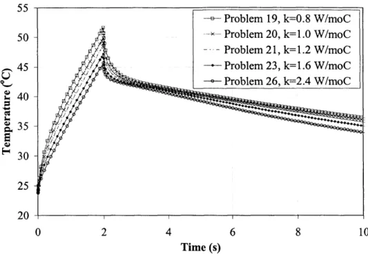
thermography. For example, Vavilov et al. (1993) reported that an increase on thermal conductivity of the sound material by 10% tends to enhance the temperature contrast, and thus, detectability, by 10%. However, increases of thermal diffusivity by 10% may amplify the contrast only 5%. Hence, thermal conductivity is the main property affecting temperature contrast between sound and flawed areas. Furthermore, considering the material properties of the flaw itself, thermal conductivity again proves to be far more relevant than diffusivity for defect detection.
Thermal diffusivity is the primary material property affecting optimum detection time. For instance, materials with high thermal diffusivity are difficult to inspect using infrared thermography due to the fast thermal response of the material. Looking at a particular engineering application, Connolly (1991) reported that low thermal diffusivity coatings bonded to high thermal conductivity substrate produce high defect detectability. On the other hand, defect detectability on specimens with high thermal diffusivity coatings and low diffusivity substrate was significantly lower. The primary reason for the low detectability was that the fast thermal event experienced at the surface of the specimen was difficult to capture.
Considering the temporal effects on thermography, Vavilov et al (1993) stated that observation time is significant for materials with high diffusivity because of their fast thermal response. High diffusivity materials are difficult to inspect using infrared thermography. CFRP composites are transitory materials with a medium value of diffusivity. Thus, capturing thermal evolutions of CFRP with infrared equipment may be a complex task. The authors reminded that for the one-sided or reflection thermography case, maximum thermal contrast occurs after the temperature maximum.
Three-dimensional heat diffusion effects through the material tend to produce rounding effects on the thermograms of the anomaly. The amount of roundness may vary depending on the material composition of the test object. Rounding effects observed on the temperature field of delaminated composites were investigated by Varis (1995). The rounding of the edges of the defect was primarily caused by the difference in thermal conductivities of the anisotropic material. In this particular case, the composite material tested included both glass and graphite fibers. The highest temperature differences were observed at the glass fiber location. The numerical simulation indicated that the temperature signal in the carbon fiber area was too small to be detected experimentally with the chosen infrared equipment. This indicates the need for specific test procedures for particular applications and materials.
Varis et al. (1995) also concluded that the effect of anisotropy was minimal when the defect was located in the interface of deeper layers.
2.3.2b Defect Characteristics
Defect characterization involves several parameters: type, size, depth, and thickness of the defect.
Type of Defect
In IR thermography testing of FRP composites, the most typical anomalies investigated are delaminations, debonds, and inclusions parallel to the surface of the specimen. This type of flaw is easily detected using infrared thermography provided the optimum testing conditions (i.e. thermal input, observation time, etc.). However, partially conductive anomalies such as resin rich/poor areas block only a portion of the heat flux through the material. This behavior produces a reduction in thermal contrast making it difficult to detect the anomaly. Cracks perpendicular to the surface of the sample are also anomalies that difficult to detect.
Cracks perpendicular to the surface of the sample require the use of nontraditional methods in order to be detected. Some of these techniques include the use of innovative heating techniques
such as electric current and moving line heating.
Post-processing of temperature data such as the calculation of the Laplacian of the temperature distribution also allows for the detection of cracks. Results show that it is possible to detect surface cracks and short and shallow cracks provided their depth is at least half the thickness of the sheet. However, cracks should have large thermal contrast resistance in order to be detected.
Size of Defect
Vavilov et al. (1993) points out the importance of size on detection. This dependence involves both diameter and thickness of the flaw.
The flaw has to be larger in diameter than its depth under the surface in order to be detectable (Rantala et al., 1991). Additionally, a decrease of flaw size produces a rounder image as well as a decrease in thermal contrast. Rantala also concluded that the estimated size of the delamination was smaller than its actual size.
For defect characterization, it is necessary to determine the relationship between the actual defect size and the estimated defect size observed in the thermograms. Numerical simulations such as finite element analysis tend to overestimate the experimental results. One of the reasons for the overestimation is the ideal testing assumptions applied to the numerical model. An additional source of size inaccuracies may arise from the selected signal measuring technique. Simple signal measuring techniques such as the selection of a temperature signal threshold above noise levels, lack precision. This technique is also highly dependent on noise and time (Vavilov, 2000). Another simple method is the full-width at half-maximum (FWHM) technique. This technique consists on determining the location at which the value of the signal is half the maximum signal. The FWHM method provides size predictions with estimation errors on the order of 15%. The FWHM tends to underestimate the true size of the defect. However, the method is simple enough to be used successfully in practice. Introducing methods that are more complex may solve the lack of accuracy. For example, a successful method is the computation of the Laplacian or second derivatives of the temperature profile. The technique involves the determination of the location at which the inflation point (d2T/dx2 =
0) of the temperature profile occurs. This technique is computationally intense. However, it provides the most accurate results.
Connolly et al. (1990) presented analytical and experimental techniques to examine carbon-carbon composite materials. Connolly et al. concluded that most infrared inspections tend to overestimate the actual flaw size to an order of 1.5 to 3 times. Thus, as further research, the authors stated that it is necessary to determine the relationship between the actual and the estimated defect size.
Depth of Defect
Infrared thermography testing is more successful on detecting superficial defects on thick specimens. The research demonstrated that testing of CFRP should be restricted to specimens containing flaws between 1.5 mm and 2 mm deep.
Detection of delaminations decreases as the depth of the defect increases (Fig. 2.3). Increasing the depth of the flaw also increases the time for maximum thermal signal and maximum thermal contrast. Additionally, partially conductive anomalies located deep in the material may be difficult to detect and quantify (Allport et al., 1988).
The depth of the flaw affects the rounding behavior of the surface temperature above the defect due to diffusivity. Deeper flaws develop more rounded edges than flaws located near the surface. For optimum detection, testing of CFRP should be restricted to specimens containing flaws between 1.5 mm and 2 mm deep (Vavilov, 1993).
Thermal Increasing Depth of Flaw
Signal
Observation Time
Fig.2.3 Effect of depth of flaw in the thermal signal and the observation time
Vavilov (2000) also investigated the effect due of multiple and overlapped defects on temperature data. For the case of multiple flaws, he observed that average temperature were higher that for cases with a single flaw. As expected, the primary reason for the increase in temperature was the influence of nearby anomalies. The problem of overlapped defect was more complex, since near-the-surface flaws may eclipse deeper anomalies. This situation tended to produce an increase in the temperature signal, which could easily be misinterpreted as a single
Thickness of Defect
The final factor for characterization of internal defects involves the thickness of the flaw or, its analogous, the thermal resistance of the flaw. The thermal resistance is directly proportional to the thickness of the flaw (Ozigik, 1985)
R =A z (2.10)
k
where R is the thermal resistance, Az is the thickness, and k is the thermal conductivity of the flaw.
Increasing the thermal resistance of the defect improves the thermal contrast at the surface of the specimen (Fig. 2.4).
Increasing Thickness of Flaw
Thermal Signal
Observation Time
Fig. 2.4 Effect of thickness of flaw in the thermal signal and the observation time
2.3.2c Thermal Input
Active infrared thermography involves the application of an external thermal impulse to the structure under testing. As such, the type, amplitude, and duration of the thermal stimulus are relevant to the optimum detection of subsurface flaws.
Several types of thermal stimulus are available for thermographers. Uniform heating, moving line heating, and spot heating are among the traditional methods. Uniform heating usually involves heating the surface of the specimen with high power lamps. However, obtaining substantially uniform heating is difficult. Line heating typically involves moving a thermal line along the surface of the specimen. Both, moving gas flame and laser sources are commonly used
for this procedure. Spot heating is the less productive mode of heating; thus, it is seldom used. From the simulation perspective, moving line heating is the most complex method since it
diffusion on the line heating method allows for the detection of cracks perpendicular to the surface, which are undetectable with traditional static heat sources.
The Joule-effect-heating technique is among the nontraditional heating methods that may be used to detect perpendicular-to-the-surface defects. The procedure consists on clamping the specimen with electrodes and applying an electric current. Moreover, the electric current flows in the direction parallel to the tested surface. Within the flawed specimen, the electrical flow creates a distinctive distribution of electric current density. By the Joule effect, this current density is converted into heat, thus, producing transient thermal effects. Currents of 2000 A to 3000 A are sufficient to detect open-to-the-surface cracks. Nevertheless, this technique is only applicable to materials able to conduct electricity.
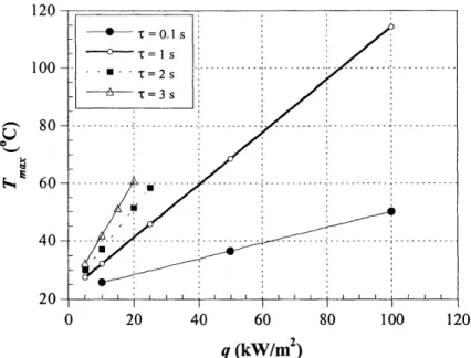
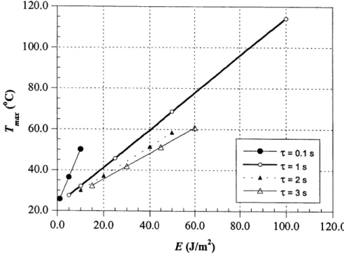
Most researchers agree that thermal pulses with high intensity and short duration produce the highest temperature gradients and thus, better flaw detection (Lulay et al., 1994). Generally, pulse duration must be as short as possible in order to attain the highest thermal contrast. For example, Vavilov et al. (1993) concluded that carbon composites benefited of heat intervals of less than 0.5 seconds. Also, defects close to the heated surface required shorter heating pulses. However, a potential practical problem is that short pulses may not be capable to deliver enough heat to raise the temperature of the surface sufficiently (Connolly, 1991). The greater the quantity of heat supplied, the greater the temperature signal. Thus, an optimum balance between the magnitude of the pulse and its duration must be found for each specific engineering
application (Starnes et al., 2002).
Vavilov (2000) studied the effect of uneven heating on thermography results. Uneven heating introduced low frequency variations in the recorded temperature signal. Vavilov suggested normalizing the temperature data in order to eliminate the effects of uneven heating.
2.3.2d Observation Time
The optimum observation time is defined as the moment of maximum thermal signal or contrast. At this instant, the image of the buried flaw emerges well defined and sharp-edged. As the time increases the image becomes increasingly round due to the diffusion effect. Additionally, increasing the depth of the flaw lengthens the time to maximum contrast.
The optimum observation time depends highly on the material properties of the test object. As previously stated, thermal diffusivity has a major effect on observation time. Hence, due to their fast thermal response, high diffusivity materials are difficult to inspect using infrared thermography. Most FRP composites used in civil infrastructure have low to medium diffusivity values; thus, they are good candidates for this testing technique.
2.3.2e Testing Mode
There are two methods of observation for infrared thermography: reflection (one-sided) and transmission (two-sided). Figure 2.5 illustrates the configurations for one-sided and two-sided testing. Each method has its advantages and disadvantages. For example, observation by reflection provides greater resolution but the thickness of the tested layer must be small. Using