HAL Id: hal-01965454
https://hal-amu.archives-ouvertes.fr/hal-01965454
Submitted on 26 Dec 2018HAL is a multi-disciplinary open access archive for the deposit and dissemination of sci-entific research documents, whether they are pub-lished or not. The documents may come from teaching and research institutions in France or abroad, or from public or private research centers.
L’archive ouverte pluridisciplinaire HAL, est destinée au dépôt et à la diffusion de documents scientifiques de niveau recherche, publiés ou non, émanant des établissements d’enseignement et de recherche français ou étrangers, des laboratoires publics ou privés.
Photochemistry of CF3Cl: Quenching of Charged
Fragments Is Caused by Nonadiabatic Effects
Vanessa de Medeiros, Railton de Andrade, Gessenildo P. Rodrigues, Glauco
Bauerfeldt, Elizete Ventura, Mario Barbatti, Silmar Do Monte
To cite this version:
Vanessa de Medeiros, Railton de Andrade, Gessenildo P. Rodrigues, Glauco Bauerfeldt, Elizete Ven-tura, et al.. Photochemistry of CF3Cl: Quenching of Charged Fragments Is Caused by Nonadiabatic Effects. Journal of Chemical Theory and Computation, American Chemical Society, 2018, 14 (9), pp.4844-4855. �10.1021/acs.jctc.8b00457�. �hal-01965454�
Photochemistry of CF
3Cl: Quenching of Charged Fragments
is Caused by Nonadiabatic Effects
Vanessa C. de Medeiros†, Railton B. de Andrade†, Gessenildo P. Rodrigues†, Glauco F. Bauerfeldt††, Elizete Ventura†, Mario Barbatti‡*, and Silmar A. do Monte†*
†Departamento de Química, CCEN, Universidade Federal da Paraíba, João Pessoa, PB, 58.059-900, Brazil
††Departamento de Química, Instituto de Ciências Exatas, UFRRJ, Pavilhão Roberto
Alvahydo (PQ), sala 44. km 7, Rodovia Br 465, Seropédica, RJ 23890-000, Brazil
‡Aix Marseille Univ, CNRS, ICR, Marseille, France
ABSTRACT
For the first time, high-level multireference electronic structure calculations have been
performed to study the photochemistry of CF3Cl, allowing a comprehensive interpretation
and assignment of experimental data concerning fluorescence, ion-pair formation, and generation of CF3 fragments in several electronic states. All studied dissociation channels correlate either with Cl or Cl in the ground state. On the other hand, CF3 fragment can be generated either in the ground or excited state. A rationalization for the nonadiabatic relaxation of CF3Cl, including the formation of an (n4s) stable state and internal conversion at multiple-state intersections, has been provided. Our results explain the anomalous quenching of charged fragment after low-energy excitation experimentally observed by separate groups. We show that the CF3+…Cl ion pair undergoes an internal conversion to the ground state, producing neutral CF3 and Cl fragments. The results also allow understanding
1. INTRODUCTION
CF3Cl (Chlorotrifluoromethane, CFC-13) has been used as a refrigerant for decades, and it
is clear that the remaining content of CF3Cl in the atmosphere has come from anthropogenic sources.1 Due to its ozone depleting and global warming characteristics, the production and use of CF3Cl have been phased out under the Montreal Protocol.2 However, its relatively long atmospheric lifetime (~640 years3) still makes it a source of great concern. Moreover, a recent report of an unexpected increase of the atmospheric CFC concentration in the last years4 has raised concerns on the possible breach of the Montreal Protocol.
Given that CF3Cl harmful effect to the ozone layer is related to Cl radicals,5-7 its photolysis has been the subject of intense research for decades.8-11 An anomalous feature in this photolysis was reported long ago by Schenk et al.12 and more recently confirmed by Simpson et al.13 Both groups showed that the Cl anion formation only occurs for energies over 16.1 eV, despite the fact that the calculated enthalpy for the CF3Cl CF3+ + Cl ion-pair reaction is only 9.2 eV. Thus, although this reaction channel is energetically accessible, the experimental data shows that, at low energy excitations, only neutral fragments are
formed. As discussed by Simpson et al.13 this anomalous behavior — whose molecular basis
has not been explained so far — is not exclusive of CF3Cl and is also observed in CF3Br and CF3I. In these species, after excitation below the ionization threshold, Br signal is also absent and I signal is much weaker than expected.
Another relevant spectroscopic feature of CF3Cl is its fluorescent signature. It has been experimentally determined that CF3Cl emission has an onset at about 10 eV,14 yielding
two broad bands, one in the UV and another in the visible.8 Nonetheless, neither of these
bands are due to CF3Cl itself, but from its CF3* fragments.
In this paper, we use uncontracted multireference configuration interactions with singles and doubles plus size-extensivity corrections (MR-CISD+Q) based on extended triple- basis sets to map the excited states of CF3Cl, including its valence and Rydberg states. With a focus on the nonadiabatic relaxation pathways along the C–Cl fragmentation, dissociation into the five lowest dissociation channels is discussed. This analysis has unveiled the molecular mechanism responsible for the anomalous quenching of the
charged-fragments. Among several excited- and ground-state reaction channels, we show that when the lowest-energy CF3+…Cl ion-pair state is formed, it couples to the ground state, nonadiabatically quenching the production of charged fragments. This sequence of nonadiabatic events helps explain not only the quenching of Cl but also allows a full
rationalization of the intrinsic darkness of CF3Cl. In addition, we show how UV emission
from the bound species could be triggered.
As some of us have discussed in ref.15, the computational chemistry of halogenated
compounds is still a significant challenge, with popular methods often delivering low accuracy results. This work is part of a more general research program to investigate such
class of compounds with multireference highly correlated methods.16-19 Working with such
high-level methods does not fully solve the accuracy problem, but it has allowed us to do an in-depth analysis of the potential energy surfaces of these compounds, revealing the diabatic transformations along reaction pathways. This is once more achieved in this work, where the picture derived for CF3Cl goes beyond this single molecule and shed light on the photodissociation patterns of other halogenfluorocarbons.
2. COMPUTATIONAL DETAILS
Cs symmetry has been used in the calculations of most of the stationary points, except the conical intersection, whose calculation has been performed without symmetry restriction. The symmetry plane corresponds to the xy plane. The Cl atom 3p lone pair along the C–Cl axis is designated as 3p, and its interaction with the 2p(C) orbital of the CF3 moiety yields the bonding and anti-bonding and * orbitals. The degenerate lone pair orbitals (3py,3pz) are referred as ne. The 2p, , *, and ne valence orbitals have been considered in the present
study. Valence and Rydberg orbitals of CF3 have also been taken into account. The valence
orbital is mainly formed by an equal combination of fluorine lone pairs nF (A1 in the C3v point group). The Rydberg orbitals are the ns, np, and npe, with n = 3 or 4 depending on whether they are localized on the C or Cl atom.18-19
For the multiconfigurational self-consistent field (MCSCF) calculations, a valence complete active space (CAS) has been chosen to comprise 8 electrons (four from the ne
orbitals, two from the bond, and two from the nF orbital). The nF orbital has been included based on the study of Washida et al.,9 which reported a valence state interspersed between some Rydberg states. Another important feature is that its inclusion leads to a sufficiently flexible occupied space at a manageable computational cost and, at the same time, keeps the correct shape of the high-lying 3p(C) Rydberg orbitals upon dissociation. The * orbital has also been included in the CAS, while the four Rydberg orbitals (ns, np, and npe) have been included in the auxiliary (AUX) space and only single CAS AUX excitations were allowed. As the actual symmetry along the potential energy curves is C3v and the calculations
have been performed using Cs symmetry, one needs to compute the average energies using
the correct pairs of A´ and A´´ roots to obtain the energies of the E states. Eleven singlet states
(at the C3v symmetry) with equal weights have been included in the state-averaged MCSCF
calculations. At the Cs group, this set of states corresponds to a total of 10 A´ and 6 A´´ roots. At the equilibrium geometry, the correspondence is the same as that obtained for the CH3Cl molecule,18 that is, 11A
1 – 11A´; 11E – (21A´ + 11A´´); 21E – (31A´ + 21A´´); 21A1 – 51A´; 31E – (41A´ + 31A´´); 11A
2 – 41A´´; 41E – (61A´ + 51A´´); 31A1 – 71A´; 41A1 – 81A´; 51E – (91A´ + 61A´´); 51A
1 – 101A´.
To generate the geometries to be used for the potential energy curves, a ground-state-relaxed scan along the C–Cl coordinate has been performed at the unconstrained multireference configuration interaction with singles and double (MR-CISD) level, employing the valence space at both MCSCF and MR-CISD levels (see Table 1).
Table 1. Active and reference spaces used for the species studied in this manuscript. When it is the case, only single RAS CAS and CAS AUX excitations have been employed.
MCSCF MR-CISD
CF3Cl RAS CAS AUX RAS CAS AUX
valence ---- ne, , * ---- ---- ne, , * ---- ref1 nF ne, , * ns, np, npe nF ne, , * ns, np, npe ref2 ---- nF, ne, , * 4s(Cl) ---- ne, , * 4s(Cl) ref3 ---- nF, ne, n, 2p ns, np, npe ---- nF, ne, n, 2p ns, np, npe CF3 ---- innera +2pσ (C) 3s, 3p ---- 2pσ (C) 3s, 3p a Except the four 1s orbitals of C and F, which are in the doubly occupied space.
In the case of the MR-CISD calculations, single-point calculations using the ref1 space (see Table 1) have been performed at the geometries obtained from a relaxed scan obtained with the valence space. The total CSF space is formed through single and double excitations from the active and doubly occupied orbitals into all virtual orbitals. Previous results19-20 shows that a frozen-core space formed by the K shell or by the K + L shells of the Cl atom (both along with the K shell of the C atom) yields virtually the same results. Therefore, the second option has been chosen at the MR-CISD level. Davidson correction (+Q)21-22 has been used to account for the size-extensivity. The d-aug-cc-pVTZ basis set for C and the aug-cc-pVTZ basis sets for F and Cl atoms23-26 have been used. This basis set combination will be referred as B1 throughout the paper.
The valence space has also been used for the geometry optimization of the ion-pair state and its nearby conical intersection between the 21A
1 and 11A1 states. Although localization of the Rydberg orbitals on the Cl or C atoms depends on the C–Cl distance, preliminary tests at the MCSCF level indicate that the B1 basis set is flexible enough to handle both situations. Besides, these tests also indicate that localization and the main characteristics of the Rydberg orbitals are the same, no matter whether one uses the B1, B2 = aug-cc-pVTZ(C,F)/d-aug-cc-pVTZ(Cl), or B3 = aug-cc-pVTZ(F)/d-aug-cc-pVTZ(C,Cl) basis set. Additionally, no significant variations have been observed for the results obtained with these three basis sets (at both MCSCF and MR-CISD levels), for the vertically excited states. Therefore, the B1 basis set has been chosen, except for geometry optimization of the conical intersection, for which the aug-cc-pVTZ basis set has been used. Cartesian coordinates for stationary structures and conical intersection are given in the Supporting Information.
The supermolecule approach for a CF3–Cl distance of 50 Å has been used to perform
single-point calculations with the B1 basis set to obtain the dissociation limits. For the ion-pair channel, the residual Coulomb energy between the charged species (0.29 eV at 50 Å) was further discounted from the potential energy of the supermolecule.
Additional full geometry optimizations have been performed for the for the ne4s(Cl)
Rydberg state (which corresponds to the 21E state near the ground state minimum), and for
ref2 space has been used (see Table 1). For the geometry optimizations of the ground state, conical intersection and the ion pair, the valence space has been used at both computational levels. These choices for the orbitals schemes are based on the relatively large energy gap between the studied states and the next one. For the ne4s, ground, and ionic states, three, two, and three states (in the C3v notation) have been averaged at the MCSCF level, respectively. In the case of geometry optimization of the higher Rydberg states, the ref3 space has been used.
Different schemes have been used for the CF3 and CF3+ fragments. At the MCSCF
level, the 1s orbitals of C and F are maintained in the doubly-occupied space. For the neutral fragment, all valence orbitals previously occupied at the restricted open-shell Hartree-Fock
(ROHF) level are in the CAS space (that is, all doubly occupied + the singly occupied 2pσ
(C) orbital). The four 3s and 3p Rydberg orbitals are in the AUX space, and only single CAS
AUX excitations are allowed. For the CF3+ fragment, the MCSCF calculation coincides
with a closed-shell SCF calculation, that is, there are no active orbitals.
At the MR-CISD level, the 1s orbitals of C and F are in the frozen-core space for both
fragments. For CF3, the valence orbitals previously doubly occupied at the ROHF level are
maintained in the doubly-occupied space at the MR-CISD level, while only the 2pσ (C) orbital is in the CAS space. As before, the four Rydberg orbitals are in the AUX space, and only single 2pσ(C) AUX excitations are included while generating the reference configurations. For the CF3+ fragment, the previously doubly-occupied orbitals at the restricted closed-shell Hartree-Fock (RHF) level are in the doubly occupied space at the MR-CISD level. As the 2pσ (C) orbital is empty in this case, there is no CAS space (for the sake of consistency with the neutral fragment) and, consequently, no AUX space. Therefore, for the cation, the CI expansion is that of a single-reference CISD wavefunction. For this system, such scheme is essentially used for obtaining the zero-point energy (ZPE) and the optimized geometry of CF3+, and this geometry is used in the calculation of the dissociation limit for the ionic channel (section 3.6). The vibrational frequencies and the geometrical parameters are in good agreement with literature data.
All geometry optimizations at the MR-CISD level have been performed through analytical gradient techniques,27-30 also available for optimization at the crossing seam, which is based on analytical nonadiabatic coupling vectors.31-32
To improve the vertical excitation energy of the nσ* state, and multi-reference
average quadratic coupled cluster (MR-AQCC)33-34 calculations have also been performed
with ref1 (see Table 1). As usual, intruder states showed up. They consist of additional CSFs (not included in the reference space) with reasonably large weights (>1%). Thus, to achieve proper convergence these individual CSFs (up to four) have been added to ref1. All MR-CISD and MR-AQCC calculations have been performed with the interactive space restriction.35
All calculations have been performed with the COLUMBUS program system.36-39
Modules taken from the DALTON program40 are integrated to COLUMBUS and have been
used to compute the atomic orbitals (AO) integrals as well as the AO gradient integrals.
3. RESULTS AND DISCUSSION 3.1. Vertically Excited States
As mentioned, 16 Cs states (10 A´ + 6 A´´), including the ground state, have been calculated, which correspond to 11 states at the C3v symmetry. These vertically excited states are assigned to the following excitations: ne* (11E); ne4s(Cl) (21E); ne4pe(Cl) (31E, 21A1, and 11A
2); ne3s(C) + ne4s(Cl) (41E); * + 4s(Cl) + nF*(31A1); 4s(Cl) + 3s(C) + * (41A
1); 4pe(Cl) (51E); 3s + 4s(Cl) (51A1). A detailed description of the vertically excited states is given in Table 2, including energies calculated at the MR-CISD, MR-CISD + Q and MR-AQCC levels, characters and weights of each state, oscillator strengths, and <r2>
expectation values obtained at the MR-CISD level. Comparison with experimental results14,
41-43 is also provided.
In the region of interest, the experimental CF3Cl spectrum features four bands.10, 14, 41-43 The experimental values for Bands 2-4 were determined by fitting the original spectral data from refs.14, 41 with a sum of six Gaussian functions in the region from 8.5 to 14.2 eV. These results are also shown in Table 2.
The lowest band, corresponding to the n* (11E) state, has its maximum at 7.7 eV and was revealed via electron energy loss spectroscopy due to its feeble intensity (f = 0.003). It has also been discussed theoretically in ref.20 The present MR-CISD+Q predicts its vertical excitation at 8.32 eV with f = 0.011. In ref.19, a vertical excitation of 8.07 eV (f = 0.003) has been obtained for this band at MR-AQCC/aug-cc-pVTZ level with a valence active space using a geometry optimized at the same level. This result was obtained with a geometry whose C–Cl distance is slightly larger (1.766 Å) than the experimental value (1.751 Å). Here, a value of 8.20 eV has been obtained at the MR-AQCC/ref1 level, but at the experimental geometry (see Table 2). If the same level is applied, but now to the optimized geometry of ref.20, 8.08 eV is obtained, which means (i) the ref1 space has similar accuracy to the valence space (at least for the n* state) and (ii) the excitation energy of n* is sensitive to the C–Cl distance.
Table 2. Vertical excitation energies (Ev, eV), <r2> values, and oscillator strengths (f) for the CF3Cl molecule obtained at the MR-CISD/ref1 level with the B1 basis set. Ev obtained at MR-CISD+Q and MR-AQCC levels are also included. Experimental band maxima (Em, eV) and oscillator strengths for Band 1 are from Ying et al.43 For Bands 2-4, experimental data are from Ali.14
The experimental data in parenthesis are from Au et al.41
Theory Experimental
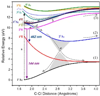
State Ev (eV) f <r2> (a02) Main configuration Band Em (eV) f
CI CI+Q AQCC 11A1 a 0.00 0.00 0.00 - 72.06 (0.83)gs 11E 8.41 8.32 8.20 0.011 76.92 (0.79)ne* 1 7.7 0.003 21E 9.64 9.67 9.56 0.201 117.07 (0.68)ne4s + (0.15)ne3s 2 9.70 (9.70) 0.125 (0.161) 21A1 10.78 10.79 10.61 0.014 149.50 (0.85)ne4pe 3 10.60 (10.57) (0.110) 0.068 31E 10.78 10.79 10.61 0.001 149.50 (0.83)ne4pe 11A2 10.78 10.79 10.61 0.000 149.50 (0.85)ne4pe 41E 10.90 10.88 0.000 152.07 (0.69)ne3s + (0.14) ne4s 31A1 13.12 12.53 0.790 88.42 (0.51)* + (0.20)4s + (0.12)nF* 4 (11.58) 11.58 (0.268) 0.227 41A1 13.85 13.21 0.024 107.7 (0.43)4s + (0.24)s + (0.11)* 51E 14.70 14.13 0.014 149.13 (0.83)4pe 51A1 14.87 14.15 0.051 150.16 (0.58)3s + (0.20)4s aGround-state energies: -796.790689165098 (MR-CISD); -796.931223965361 (MR-CISD+Q); -796.9701875737 (MR-AQCC).
We recall that the experimental band maximum does not correspond to the vertical excitation energy, which is systematically displaced to the blue by ~0.1-0.2 eV.44 Thus, in the comparison above, a band maximum at 7.7 eV should actually correspond to a vertical excitation of about 7.8-7.9 eV, which significantly reduces the computational error. Throughout the paper, we still draw comparisons to the band maximum, as this is the hard value delivered by the experiments. Nevertheless, we should bear this blueshift in mind when evaluating the accuracy of the calculations.
Next in energy, the experiments show a bright band at 9.70 eV, and a weaker band at
10.60 eV.10, 14, 41-42 At MR-CISD+Q, these values are at 9.67 and 10.79 eV (Table 2). The
bright band (band 2) corresponds to the excitations into the 21E state, with clear 3s/4s Rydberg character (<r2>=117 a
02). The weaker band (band 3) contains excitations into the quasi-four-fold degenerate 31E, 21A
1, and 11A2 states, also with Rydberg character (4pe), and the 41E (3s/4s) state.
From the formal standpoint, the occurrence of both 3s and 4s Rydberg orbitals in the ground-state minimum region (at C–Cl ~1.7 Å) leads to appearance of two states formed from the admixture of the ne3s and ne4s configurations (21E and 41E, see Table 2). In the 21E, contributing to band 2, one has an anti-symmetric, while in 41E (contributing to band 3), one has a symmetric combination of these two configurations.
A strong band (band 4) comes next, with experimental maximum at 11.58 eV (f = 0.227-0.268). The main vertical excitation to this band computed at MR-CISD+Q is at 12.53
eV (f = 0.790), corresponding to a valence (*) excitation into the 31A
1 state. The strong deviation between theory and experiment by about 0.95 eV (and also in the oscillator strength, which is off by a factor 3), indicates the limits of the current level. Such large blue-shift is a well-known problem in this class of methods, mainly arising from insufficient dynamic polarization (see, e.g., Wu et al.45). In the case of CF
3Cl, to correct for such effect, we would have to include the C-F orbitals in the active space to allow them to respond to the C-Cl polarization (which is computationally unaffordable). The inaccuracy of the MRCI oscillator strength is also connected to the dynamic polarization effect but at another level. If dynamic CF polarization were considered, it would lead to Cl contraction,46 reducing the predicted oscillator strength.
The need for larger CI expansions to describe band 4 is also implied by the significant Davidson corrections (+Q) obtained for the 31A
1 and the other states contributing to this band. In fact, few additional Rydberg states, not included in this study, are expected in the range from 11.48 to 12.31 eV.47 Thus, they are interspersed between the 41E and 31A
1 states, which can significantly affect the properties of these two states. To the best of our knowledge, it is the first time that the four highest lying states shown in Table 2 are studied for CF3Cl. Some high-lying states in the case of CH3Cl also involve excitations from σ to Rydberg orbitals,17-18 but in that case, they have much lower multiconfigurational character. For both systems, the state containing the σσ* configuration leads to the most intense transition (cf. Table 2 and also Table 1 of ref.18). However, a significant difference is that, while for CH
3Cl this configuration has a small (though non-negligible) weight (in the 41A
1 state18), for CF3Cl it appears as the main configuration for one of the studied states, 31A
1 (see Table 2). Although large deviations have been obtained for 11E and 31A
1, the full set of states reported here improves considerably the theoretical description of the spectrum of vertically excited states of CF3Cl. Moreover, a complete description of the vertical excited states at multireference level including all missing Rydberg states (in the studied energy range) is currently computationally impracticable. In the next sections, we apply MR-CISD wavefunctions to investigate the photochemistry of C–Cl bond breakage, focusing mainly on excitations up to band 3, where we have succeeded to deliver a semi-quantitatively correct description of the excited states in the Franck-Condon region.
Additional information about the absorption spectrum, including comparison to other methods, is provided in the Supporting Information.
3.2. Potential Energy curves and Photodissociation Pathways
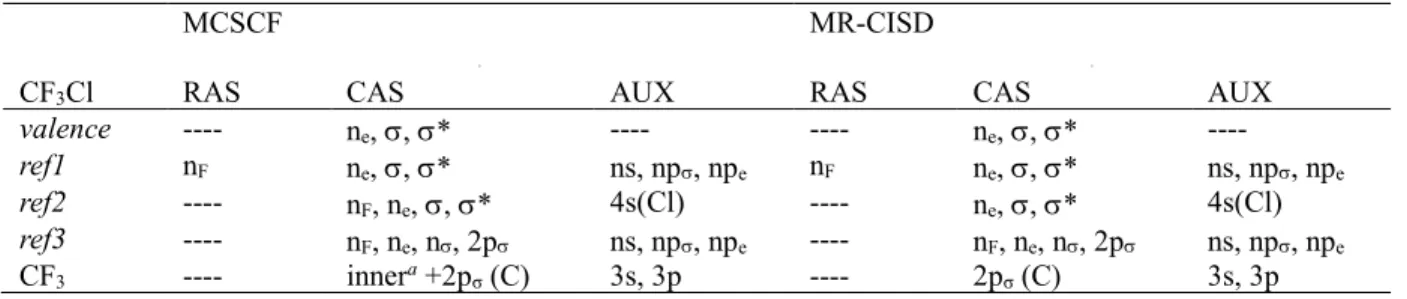
Potential energy curves along the C–Cl coordinate for ground-state relaxed geometries have been calculated under Cs symmetry restriction for all electronic states. They are shown in Figure 1 for the corresponding C3v states. At the right, the relaxed dissociation limits, which are discussed later in Section 3.6, are shown as well.
Figure 1. Potential energy curves along the C–Cl coordinate for ground-state relaxed geometries. Calculated at the MR-CISD/ref1/B1 level. Dissociation limits are (in C3v notation):
(1) CF3(2pσ(C), 12A1) + Cl(2P); (2) CF3+(11A1) + Cl(1S); (3) CF3(3s, 22A1) + Cl(2P); (4) CF3(3pσ,
32A
1) + Cl(2P); (5) CF3(3pe, 12E) + Cl(2P). At the right, the dissociation limits computed at the
same level for the state-specific relaxed geometry are indicated.
The calculation of a potential energy profile like in Figure 1 always implies in certain arbitrary choice of the geometries. Ideally, the geometries should be optimized for the state that the molecule populates at each distance. Nevertheless, when multiple states are calculated, there is not a unique choice. Throughout this paper, unless otherwise stated, we work on ground-state relaxed geometries. With such a choice, an energy profile like in Figure 1 strictly tells the energy spectrum felt by a molecule slowly dissociating in the ground state. This choice has the side-effect of destabilizing the excited states, and this effect can be already noticed in the striking differences between the asymptotic levels of the curves and the corresponding relaxed dissociation limit. Despite the geometry representation chosen for the profiles, the topology of the curves should still be constant. The crossing and avoided crossings arising from the state transformations along the dissociation may change in energy and position, but they still occur qualitatively in the same way for geometries relaxed in another state.
Dissociation along the two lowest lying potential energy curves leads to the CF3 and Cl fragments in their corresponding electronic ground states (channel (1) of Figure 1). The character of the molecular orbitals smoothly changes as the C–Cl interatomic distance
increases, from the initial set of MOs described above to the expected orbitals belonging to the isolated fragments. That is, from the and * molecular orbitals at CF3Cl, to the n(Cl) and 2p(C) orbitals at the dissociation limit. It is accompanied by a change of ground state configuration from the ()2(*)0 at the minimum to (n)1(2p)1 at the dissociation limit. Avoided crossings are also responsible for the wavefunction character changes, which guarantee the correct dissociation limit, as discussed later. The potential energy of the first excited state, vertically assigned as (ne)1(*)1, evolves to the (ne)1(2p)1 configuration along a typical repulsive curve. It also leads to the ground-state dissociation limit (see Figure 1), as the three n(Cl) orbitals become degenerate at very large distances.
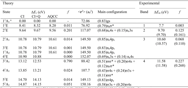
Figure 2. Detailed view of the region between 1.8 and 4 Å of Figure 1. The vertical dashed arrow (a) indicates a Franck-Condon absorption into the bright 31A
1 state from which
nonadiabatic transitions start. Shaded areas (b-e) indicate important regions of state crossings. Possible fluorescence emissions from 21E are also shown. The fluorescence λ values have been
computed at the MR-CISD+Q/ref1 level.
As the C–Cl interatomic distance increases to ca. 2.5 Å, the Rydberg orbitals’ character also smoothly changes from a Rydberg 4s (centered at the Cl atom, at the equilibrium geometry) to a Rydberg 3p (centered at the C atom). Rydberg 4pe(Cl) orbitals
(22A
1) + Cl (2P) dissociation limit along the 21E curve (channel (3)), the vertically-assigned configuration ne4s becomes the ne3s.
In Figure 2, we deliver a more detailed picture of the potential energy curves in the short C–Cl region. After high-energy excitation into the bright 31A
1 state (a), there is a clear nonadiabatic pathway to transfer the population all way down to the 21E
1 state, indicated by the sequence of dashed arrows. The main nonadiabatic features in this energy region are (i) the multi-state crossing involving 31A
1, 41E, 11A2, and 31E at 2.8 Å (indicated by the shaded area b); (ii) the multi-state crossing involving 41E, 11A
2, 31E, and 21A1 at 1.8 Å (shaded area c); and (iii) the 21E/21A
1 crossing at 2 Å (shaded area d). At the 21E1 (ne4s) state, which can also be directly excited, fluorescence can (in principle) take place, or the molecule can still internally convert to the ion-pair state through the 21E/21A
1 crossing. The relaxation of the 21E
1 state is discussed in Section 3.3; the competition between fluorescence and internal conversion is discussed in Section 3.8. Relaxation in the 21A
1 ion-pair state (shaded area e) leads to a conical intersection between it and the 11A
1 (not shown in the figure), which is discussed in more details in Section 3.7. During this nonadiabatic relaxation, depending on the vertical excitation, the molecule may dissociate forming neutral fragments along channels (1) and (3) and charged fragments in the channel (2) (see Section 3.6).
Figure 3. Optimized structure of the ne4s state (31A´) computed at the MR-CISD/ref2/B1 level.
3.3. Characterization of the ne4s state
Upon excitation into the ne4s (21E; or 31A´ + 21A´´ in Cs) state, the system is subjected to the Jahn-Teller (JT) effect, thus leading to symmetry lowering from C3v to Cs. Full geometry
optimization of the 31A´ state indicates a small JT effect, as the departure from C
3v symmetry is relatively small (see Figure 3), leading to an energy difference between 31A´ and its
counterpart (21A´´) of only 0.03 eV (at the MR-CISD+Q/ref1 level). The C–Cl interatomic
distance at the minimum energy geometry of ne4s is 2.036 Å. The main configurations at the optimized geometry of 31A´ are 0.60 n
e4s + 0.22 ne3s (MR-CISD/ref1).
Table 3. Vibrational frequencies, energy differences (ΔE, in eV) and oscillator strengths to lower states, for the ne4s state, computed at the MR-CISD level with the B1 basis set. Vibrational
frequencies of CF3Cl in the ground state are also given for comparison.
Vibrational frequencies
Description grounda ne4sb
ClCF angular deformation (A´´) -- 176.0
C – Cl stretch -- 236.9
ClCF angular deformation (A´) -- 273.2 ClCF angular deformation 358.5c --
C – Cl stretch 494.4 --
CF3 angular deformation (A´) 592.2c 576.0 CF3 angular deformation (A´´) -- 576.1 CF3 umbrella mode (A´) 836.3 651.4 CF3 symmetric stretch (A´, breathing mode) 1204.7 1018.0
CF stretch (A´) 1345.3c 1511.6
CF stretch (A´´) -- 1513.2
Electronic Properties (ne4s)
Lower state ΔEd f ( 103)b
nσ* 2.83(438 nm) e 2.167
Ground 8.61 (144 nm) 55.401
a Computed with the valence space; b computed with the ref2 space; c doubly degenerate vibrations; d single-point calculations performed at the MR-CISD+Q/ref1 level; e average value.
Frequency calculation shows the ne4s state as a minimum, and its vibrational frequencies, along with the oscillator strengths to the lower states, are given in Table 3. As
of the ground state (in 358.5 cm-1) is split into two vibrations with significantly lower frequencies (176.0 and 273.2 cm-1) for the n
e4s state. Similarly, the C–Cl stretching frequency is also reduced, but the effect is much stronger, which is consistent with an increase of 0.262 Å (from 1.774 to 2.036 Å) of the C–Cl bond distance. Thus, this bond is significantly weakened in the ne4s state. A tiny reduction has been obtained for the degenerated CF3
angular deformation mode (from 592.2 to 576 cm-1). However, for the umbrella deformation
mode (836.3 cm-1) the reduction is much larger, which can be explained by its significant
coupling with the C–Cl stretching mode. A similar effect is observed for the CF3 breathing mode. However, for the degenerated CF stretching mode, the increase from 1345.3 to 1512
cm-1 (mean value) can be explained by the stronger C–F bonds in the n
e4s state (with bond distances of 1.261 and 1.264 Å, as compared with the value of 1.307 Å in the ground state).
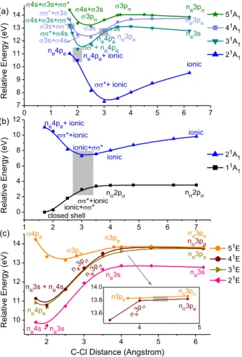
3.4. Potential energy curves for the 1A1 states The calculated potential energy curves for the 1A
1 states, in the region from 1.7 to 6.2 Å, are shown in Figure 4 (a) and (b). Four avoided crossings can be clearly identified. The first one at ~1.7 Å makes the configuration *+3s, previously in the 41A
1 state, to become the
*+4s configuration in the 31A
1 state. The explanation for this change from 3s to 4s is
the near degeneracy between the 4s(Cl) and 3s(C) orbitals caused by the quantum defects 4s
= 2.09 (ref.47) and
3s = 0.912,16 resulting in 4 – 4s 3 – 3s. Another evidence for such near degeneracy is the strong coupling between the 3s and 4s configurations, leading to a symmetric and anti-symmetric combination between them in the 51A
1 and 31A1 states,
respectively (at ~1.7 Å). At ~2.0 Å, these combinations are observed between the 51A
1 and 41A
1 states.
The second avoided crossing takes place at ~2.0 Å, bringing the * configuration to the 21A
1 state, while the ne4pe configuration (which later becomes ne3pe) is transferred to the 31A
1 state (see Figure 4 (a)). The change from ne4pe to ne3pe configuration is due to the change of localization of the npe Rydberg orbitals, from the Cl to the C atom, in the region between ~2.0 and 2.5 Å. The same holds for the 4s orbital, which becomes the 3p orbital.
In the case of the third avoided crossing at ~3 Å, the ne3pe and 3s configurations are
interchanged between the 31A
11A
2, 31E, and 41E states are almost degenerate. The primary configuration of the first three states is ne3pe, while for the latter it is ne3pσ.
The last avoided crossing is between the 21A
1 and 11A1 states (at ~2.8 Å, see Figure 4 (b)). It brings the ionic configuration — (n)2(2p or 2(2p, depending on the C–Cl distance — from the 21A
1 to the 11A1 state and then back to the 21A1 state. After the avoided crossing, the dominant configuration of the 11A
1 state becomes n2p, consistent with a homolytic dissociation. This complex state-crossing pattern occurs because the ion-pair state has a minimum that is slightly below the energy of the n2p state. This minimum is discussed in Section 3.7.
Figure 4. Ground-state relaxed potential energy curves along the C–Cl coordinate for: (a) 1A1
states (from 2 to 5); (b) the 11A
1 and 21A1 states; and (c) 1E states. The shaded areas indicate
regions of avoided crossings. The inset in (c) highlights the avoided crossing between the 41E and
51E states at ~4.3 Å. All data at MR-CISD/ref1/B1 level.
0 1 2 3 4 5 6 7 7 8 9 10 11 12 13 14 1 2 3 4 5 6 7 0 2 4 6 8 10 12 2 3 4 5 6 10 11 12 13 14 4 5 13.6 13.8 14.0 ne3pe ne3p 3p 3p 4s+3s 4s+3s+* ne3pe 3s 3s+* 3s+4s *+3s 4s+3s+* ne3s ne4pe *+ ne4pe ionic *+ ionic ne4pe+ ionic R e lati ve E n e rg y (e V ) 51A 1 41A1 31A 1 21A 1 ne4pe *+4s 3s (b) ne4pe+ ionic *+ionic *+ionic ionic+* ionic n2p R e lati ve E n e rg y (e V ) 21A 1 11A 1 ionic+* n2p ionic closed shell ne3p n3pe 3pe 4pe n3pe ne3p ne3s + ne4s ne3pe ne3p ne4pe ne3s ne3s R e lati ve E n e rg y (e V ) C-Cl Distance (Angstrom) 51E 41E 31E 21E ne4s + ne3s (c) ne3p n3pe n3pe ne3p (a)
An important difference between the CH3Cl and CF3Cl molecules is the occurrence of an avoided crossing between the 21A
1 (ionic) and 31A1 (n3s) states of the former for a C– Cl distance of ~15 Å.18 In the case of CF
3Cl, the absence of such a crossing can be explained by the larger excitation energy of the 3s state of the CF3 radical, as compared to that of CH3. As the orbital becomes more localized in the Cl atom (for larger distances), it changes to n, and the configurations involving this orbital change accordingly. Thus, 3s and 3p configurations become n3s and n3p, respectively (see Figure 4(a)). The main contribution to the ionic configuration of the 21A
1 state is associated with an electron transfer from the 2p(C) orbital of the CF3 radical to the Cl atom. However, for C–Cl distances larger than ~3 Å, another ionic configuration, associated with an electron transfer from the nF orbital of the CF3 radical to the Cl atom, also becomes important, with weights varying from ~0.12 to 0.19, for C–Cl distances larger than ~3 Å. Therefore, for such C–Cl distances, the ionic configurations, shown in Figure 4 (a) and (b), are actually an admixture between the two types of ionic configurations. It is important to point out that the nF orbital has been included in the active space to guarantee the correct shapes for the 3p orbitals for very large distances.
3.5. Potential energy curves for the 1E states
The computed potential energy curves for the 1E states, for C–Cl distances in a range from 1.7 to 6.2 Å, are shown in Figure 4 (c). As in the case of the 1A
1 states, the interaction between the ne3s and ne4s configurations in the 21E and 41E states can be explained by the near degeneracy between the 3s and 4s Rydberg orbitals.
The (ne(4pe)1 and (ne)1(3pe)1 configurations are connected along the 31E curve (see Figure 4 (c)), giving rise to the CF3(3pe, 12E) + Cl(2P) dissociation limit (channel (5) of Figure 1). The (ne(4pe)1 configuration is dominant in the 11A2 curve and is also connected to the (ne)1(3pe)1 configuration, observed at larger distances and contributing to the channel (5) too.
Along the 41E curve, the n
e3s + ne4s and the ne3p configurations are connected due to a gradual loss of importance of the ne3s configuration, along with a transformation of the 4s orbital into the 3p orbital (see Figure 4 (c)). In the case of the 51E curve, the 4pe configuration first becomes pe due to a change of localization of the npe orbital, first
centered on the Cl atom (n = 4) and then on the C atom (n = 3), for larger distances. Afterward, the pe configuration becomes npe due to the transformation of the orbital in the n orbital, centered on the Cl atom.
The only avoided crossing for the 1E states has been observed between the 41E and 51E states, at ~4.3 Å. Such avoided crossing interchanges the n
e3p and n3pe configurations between these two states. However, the energy separation after the crossing is so small that they still are part of the same dissociation limit, CF3 (12E) + Cl (2P).
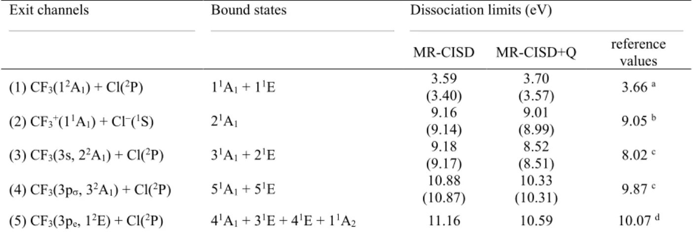
3.6. Dissociation limits
MR-CISD calculations were done for a C–Cl distance of 50 Å to get the dissociation limits.
For each limit, the CF3 geometry is relaxed in the corresponding ground or excited state.
These relaxed CF3 geometries are reported in Ref.16 Similar procedure was used for the ion-pair dissociation limit, but relaxing CF3+ in the ground state. All relaxed dissociation limits are illustrated in Figure 1 and given in Table 4.
Table 4. Dissociation limits computed at the C–Cl distance of 50 Å at MR-CISD+Q/ref1/B1 level. The values are calculated for the CF3/CF3+ optimized in its final state. Results in parenthesis
include ZPE. The exit channels are given as well.
Exit channels Bound states Dissociation limits (eV)
MR-CISD MR-CISD+Q reference values (1) CF3(12A1) + Cl(2P) 11A1 + 11E 3.59 (3.40) 3.70 (3.57) 3.66 a (2) CF3+(11A1) + Cl(1S) 21A1 9.16 (9.14) (8.99) 9.01 9.05 b (3) CF3(3s, 22A1) + Cl(2P) 31A1 + 21E 9.18 (9.17) (8.51) 8.52 8.02 c (4) CF3(3p, 32A1) + Cl(2P) 51A1 + 51E 10.88 (10.87) (10.31) 10.33 9.87 c (5) CF3(3pe, 12E) + Cl(2P) 41A1 + 31E + 41E + 11A2 11.16 10.59 10.07 d a From ref.48; b Computed from the values taken from refs.48-49 along with the experimental dissociation energy of CF3Cl.48c Taken from the corresponding adiabatic excitation energies of the CF3 radical16 at the MR-CISD+Q level summed to the experimental dissociation energy48 (3.66 eV); d In this case, the ground-state dissociation energy used (3.74 eV) does not include ZPE.
The reference ground-state dissociation energy reported in Table 4 has been calculated for 0 K enthalpies available from NIST for CF3Cl, CF3, and Cl (-702.71, -469.19, and 119.63 kJ.mol-1, respectively), along with ZPE (CF
3Cl: 3306 cm-1 and CF3: 2663.9 cm -1).48 For the ionic channel, the reference dissociation limit has been estimated by taking into account the electron affinity of Cl (3.613 eV, ref.48) and the adiabatic ionization energy of CF3 (9.0 eV, ref.49) summed to the ground state dissociation energy. Adiabatic excitation energies for CF3 (4.36, 6.21, and 6.33 eV for the 3s, 3p, and 3pe states), obtained at MR-CISD+Q with the B1 basis set,16 have been added to the ground-state dissociation energy to estimate the other reference dissociation limits.
As can be seen from Table 4, there is good agreement between the MR-CISD+Q results and the reference values. For the lowest two channels, the deviation is smaller than 0.1 eV, indicating that basis set superposition error (BSSE) should not play a significant role. This conclusion is not surprising given the high quality of the B1 basis set. For the three other channels, the MR-CISD+Q values are about 0.5 eV larger than the reference values, pointing once more to the limitations of the active and reference spaces adopted in this study to describe highly-excited states.
3.7. Characterization of the CF3+ + Cl Ion Pair
As in the case of CH3Cl,18 the profile of the 21A1 state in Figure 1 suggests the occurrence of a stationary point correlating with the CF3+ + Cl dissociation channel at ~3Å. Because at this distance one has a small weight of the (nF)1(2p)1 configuration, a full geometry optimization was performed (with the B1 basis set) excluding this orbital from the CAS. The
nF orbital was moved to the doubly occupied space at both MCSCF and MR-CISD levels to
make the calculation feasible.
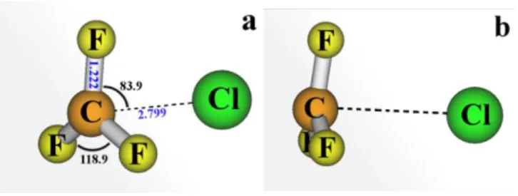
After the full geometry optimization, the structure of the CF3+…Cl ion pair shown in Figure 5 is obtained. As can be seen from this plot, the CF3+ group is not planar, and the F atoms are in a plane whose distance to Cl is smaller than the C…Cl distance. This structure is an extreme on the potential energy surface, belonging to the C3v symmetry group and with the C–Cl bond distance much shorter (by 0.5 Å) than that in the CH3+…Cl ion pair.18 Although we assumed that this geometry for the CF3+…Cl ion pair is a minimum; we could
not verify it due to convergence problems in the normal mode analysis caused by the quasi-degeneracy of this state with the 11A
1 state. In fact, we discuss later in this section that a conical intersection between the 21A
1 and 11A1 states lies near this minimum.
Figure 5. Two different views of the CF3+…Cl ion-pair structure at the MR-CISD/valence/B1
level. Important geometric parameters are given in (a). In (b), one can see that the plane containing the F atoms is slightly closer to the chloride than the C atom, with a corresponding FFFC dihedral angle of 12 degrees.
The CF3+…Cl ion-pair minimum lies 4.62 eV (4.99 eV with ZPE correction) above
the ground-state minimum (MR-CISD+Q/ref1/B1 level), and it has a large stabilization energy of 4.4 eV (4.0 eV with ZPE) compared with the CF3+ and Cl species separated by a distance of 50 Å. This value makes it much more stable (by 2.42 eV with ZPE) than the CH3+…Cl ion pair.18 Even after an additional stabilization of the CH3+…Cl ion pair due to
the CH…Cl hydrogen bond formation (now yielding the H
2CH+…Cl complex12), the CF3+…Cl ion pair remains considerably more stable (by 1.46 eV).
As expected, the polarity of the CF3+…Cl ion pair is like that of CH3+…Cl, with a dipole moment of 11.56 D (MR-CISD/ref1/B1 level), but with a much larger charge separation (from CF3+…Cl-), with = 1.42 (from Mulliken’s population analysis). This
single-point calculation also yields the following ionic configuration:
0.70(nF)2(2p)0(n(Cl))2 + 0.14(nF)1(2p)1(n(Cl))2. Thus, differently from CH3+…Cl,18 in the case of the CF3+…Cl ion pair, the configuration 2pn(Cl)(or σσ*, depending on the C–Cl distance) has negligible weight. Another important characteristic of the CF3+…Cl ion pair state at the minimum is its proximity to the next low-lying 1A
1 (n2p) state, which at the level used for optimization (MR-CISD/valence/B1) is only -0.1 eV. Thus, the CF3+…Cl ion pair state effectively becomes the ground state of the pre-dissociated species but closely
followed by the n2p state. Naturally, we expect to find a conical intersection between these states nearby.
A minimum-energy conical intersection was optimized between the 21A
1 and 11A1 states. The structure of this conical intersection is virtually identical to that of the ion-pair minimum (see Figure 5). It lies 5.20 eV above the optimized structure of the ground state (MR-CISD+Q/valence/aug-cc-pVTZ level). Computed at the same level, the ion-pair minimum is at 4.98 eV, therefore, 0.22 eV below the intersection.
In Table 5, one has the vertical excitation energies, oscillator strengths (f), and the main configurations for the nearby electronic states at the minimum and conical intersection structures. As can be seen from this table at both structures, the states are very close at the
MR-CISD level, with a maximum difference of 0.17 eV for the 11E state at the structure of
the ion-pair minimum. Upon inclusion of size-extensivity correction (MR-CISD+Q), all differences increase, with a maximum value of 0.36 eV. Moreover, the states’ ordering change at this latter level, such that the ion-pair minimum and the conical intersection become the lowest states at their own structures. As the ion-pair minimum and the conical intersection structures have very similar geometries, Table 5 indicates that subtle geometric changes in the ion-pair structure greatly enhance the coupling between the (2p)1(n(Cl))1 and the ionic configurations.
Table 5. Vertical excitation energies (in eV), oscillator strengths (f) and main configurations for the nearby electronic states in the minimum and in the conical intersection structures. Values have been computed with the valence space along with the aug-cc-pVTZ basis set and are relative to the ground state minimum.
State E (eV) f nearby state a main configuration CIb CI+Qc ion-pair minimum 5.35 4.98 ---- ---- 0.67 ionic + 0.18 (2p)1(n(Cl))1 5.25 5.30 0.011 11A1 0.68 (2p)1(n(Cl))1 + 0.18 ionic 5.18 5.34 < 10-6 11E 0.86 ne2p conical intersection 5.35 5.20 ---- ---- 0.78 (2p)1(n(Cl))1/0.77 ionicd 5.26 5.43 6x10⁻⁶ 11E 0.86 ne2p
a The distinction between 11A1 and 21A1 states is based on their CI energies; b MR-CISD; c MR-CISD+Q; d Pair of degenerate states (11A1/21A1) characterizing the conical intersection.
As can also be seen from Table 5, the f values are almost negligible for transitions involving the 11E state, at both structures. At the ion-pair structure the f value corresponding to the ion-pair 11A
1 transition is very similar to that of the ground state 11E (n*) (see Table 2). However, the former transition is in the infrared region and can thus take place by IR absorption and, if it does, it can either lead to the neutral ground state fragments or to the ground state minimum. As discussed below, conversion from the ion-pair to the conical intersection can also lead to the same products.
In Figure 6 (a), the branching space vectors g (gradient difference) and h (nonadiabatic coupling) are shown. The gradient difference combines CF3 breathing with the C–Cl bond stretching, while the nonadiabatic coupling vector is dominated by the umbrella
mode. The double cone around the 21A
1/11A1 intersection is shown in Figure 6(b).
Figure 6. (a) Normalized branching space vectors g (gradient difference) and h (nonadiabatic coupling) obtained for the conical intersection between the 21A
1 and 11A1 states. (b) Double cone
plot characterizing this conical intersection. The arrows in (b) indicate the directions to the Franck-Condon (FC) region and C–Cl dissociation.
Internal conversion from the ion pair to the ground state at the 21A
1/11A1 conical intersection implies an electron transfer because the fragments in the ground state are neutral. This transfer should, in principle, reduce the efficiency of the intersection, keeping the molecule diabatically trapped in the ion-pair state. Note, however, that starting from the intersection, the directions with positive and negative h keeping g = 0 is flat due to the existence of the ion-pair minimum closely below the intersection. Therefore, the wave packet sitting at the ion-pair minimum should continuously experience nonadiabatic interactions, which should act against the diabatic trapping, rendering an ultrashort lifetime for the CF3+…Cl ion pair.
After the internal conversion, CF3Cl may be recovered or dissociate into neutral fragments. The double cone is nearly symmetrical in the g direction and strongly tilted in the
h direction, sharply stabilizing the 11A
1 energy along negative h. This topographical feature creates a bias towards recovering CF3Cl. Nevertheless, the final dissociation yield also depends on the nuclear momentum and this information is not available in the present work. The 1A1/2A1 conical intersection marks a sharp distinction between CF3+…Cl and CH3+…Cl ion pairs. In the latter, there is no low-lying conical intersection, and the pair reorganizes as H2CH+…Cl forming a CH…Cl hydrogen bond.18
As discussed in the Introduction, the appearance of Cl in the dissociation of CF3Cl only occurs for excitations above 16.1 eV,13 although the ion-pair dissociation channel lies much lower, at 8.99 eV (MR-CISD+Q, Table 4). Our results can directly rationalize this fact. The 21A
1 is the only low-energy state that could lead to the formation of Cl (and CF3+). Because it can easily form a conical intersection with the 11A
1 state, this state nonadiabatically deactivates in the region of the ion pair, either yielding the neutral CF3 and Cl fragments in their respective ground states through the dissociation channel (1) or
regenerating the ground state of CF3Cl. Simpson et al.13 showed that the same anomalous
photochemistry is observed in CF3Br and CF3I whose Br and I signals at low energies are much weaker than expected. It is clear now that these other species should have the same kind of conical intersection between their lowest ion-pair state and the ground state.
3.8. Fluorescence of CF3Cl
Fluorescence of CF3Cl has been measured after excitation in the range from 8 to 22 eV.10, 14
The total fluorescence has an onset about 10 eV,14 with peaks at 11.29 and 15.90 eV, and
shoulders at 10.9 and 13.2 eV. For excitation at about 11 eV, the emission shows two broad bands, one in the UV at 5-5.6 eV and another in the visible around 2-2.25 eV.8 All these emission features have been assigned to CF3* emission. In this section, we discuss the reason why CF3Cl does not fluoresce.
The potential energy profiles along the C–Cl bond suggest the occurrence of several candidates for excited states minima in the 21E, 51A
1, 51E, 41A1, and 31A1 states (Figure 2).
Nevertheless, only in the case of the 21E state, a minimum has been obtained (cf. Section
3.3). During the geometry optimizations of the remaining states at the MR-CIS level under Cs symmetry (101A´ from 51A1; 91A´ or 61A´´ from 51E; 71A´ from 31A1,and 71A´ from 41A
1) nearly triply-degenerate states have been obtained, thus preventing completion of the geometry optimizations. These near-degeneracies between multiple states suggests the existence of multiple-state conical intersections,50 which can deactivate the excited states through a cascade of nonadiabatic processes, eventually bringing the molecule to the ion-pair state 21A
1. If this state is populated, another conical intersection (discussed in Section 3.7) can bring the system to the ground state, eliminating any possibility of photoemission.
Thus, if any fluorescence from CF3Cl emission can occur, it should happen only for
excitation near the origin of the ne4s state (9.16 eV; 135 nm), as any higher value would enhance the internal conversion (and tunneling) to the 21A
1 state. Thus, after exciting the ne4s band origin, this state could irradiate and relax either to the 11E or 11A
1 states. If the target state is the 11Ethe emission lies in the visible, with an energy difference of 2.83 eV (438 nm) calculated at the MR-CISD+Q/ref1 level. If the target state is the 11A
1 the emission is in the far UV, with 8.61 eV (144 nm) at the same level. These two transitions are schematically depicted in Figure 2. Although the oscillator strength values given in Table 3 indicate that both are allowed transitions (especially the UV emission), the computed radiative lifetimes yield values of 1.3 s and 5.6 ns for the visible and UV emissions, respectively. Therefore, due to the much longer radiative lifetime for the visible emission,
the ne4s state excited in the band origin would likely either emit in the UV or tunnel to 21A1 before any possibility of visible emission.
4. CONCLUSIONS
For the first time, high-level electronic structure calculations at the MR-CISD+Q level have been performed to study the potential energy curves of valence and Rydberg states of CF3Cl along the C–Cl coordinate. They allowed a comprehensive interpretation and assignment of experimental data concerning fluorescence, deactivation of the ion pair, and generation of CF3 fragment in several electronic states.
States converging to the five lowest dissociation channels were investigated. None of these channels leads to the formation of excited Cl atom, although most of the initial
Franck-Condon excitations are located at the Cl atom. These channels, however, can produce CF3
radical either in the ground (channel (1)) or in different excited states (channels (3)-(5)). Channel (2), in turn, leads to a CF3+…Cl ion-pair production.
The topography of the lowest states is schematically illustrated in Figure 7. This qualitative picture collects some of the major features revealed by the calculations.
The ne4pe state, which becomes the ion-pair state (ionic), plays a critical role in CF3Cl dissociation. Due to the strong Coulomb interaction between CF3+ and Cl, it stabilizes up to become nearly degenerated with the * state, where it has a minimum (Section 3.7). During this stabilization, it also crosses the ne4s and the ne* states. The dissociation energy of this state, corresponding to the channel (2), is the third in energy (Table 4), which means that the ion-pair state re-cross all those states again on its way to dissociation.
The ne4s state also features a minimum (Section 3.3), and it dissociates along the channel (3) (the second in energy, Table 4). Curiously, the dissociation energy is below the energy of the minimum, meaning that they are separated by a barrier. This barrier is caused by interactions with the ne3s state, which also dissociates along the channel (3).
Figure 7. Schematic picture of the CF3Cl dissociation in the low-lying excited states. From
each crossing, the system can follow two new pathways. From the conical intersection (CI), ground state regeneration or generation of the neutral ground state fragments can take place. The values given do not include zero-point corrections and have been obtained at the MR-CISD+Q level with the ref2 space for the ne4s state and with the valence space for the remaining structures.
Experimentally, CF3Cl is known for its anomalous photolysis, which does not produce Cl even though it is energetically allowed.12-13 The present results explain this phenomenon. The CF3+…Cl ion pair minimum is in the vicinity of a conical intersection with the ground state (ionic in Figure 7). At this intersection, CF3Cl either returns to the ground state or dissociates into neutral fragments. This analysis should help rationalize why other halogenfluorocarbons like CF3Br and CF3I analogously exhibit weak anion signals.
The excited-state energy profile shows several easily accessible state intersections connecting states up to the fourth absorption band. In particular, the existence of multiple-state intersections, in two geometrical spots at C–Cl distances of ~1.7 and 3.0 Å, can promote several nonadiabatic events, bringing the molecule to lower excited states or driving it to
dissociation. This relaxation pattern precludes any relaxation to an excited-state minimum from where it could fluoresce. The only possible photoemission would arise from excitation into the band origin of the ne4s state, from where radiative decay to 11A1 would result in far-UV emission at 144 nm.
Excited-state photodissociation is still an outstanding challenge for computational theoretical chemistry. As we have seen, even its description for a small molecule like CF3Cl requires pushing high-level multireference methods to their limits. The construction of active and multireference spaces composed of semi-independent subspaces, as done here, sets an optimal strategy, which we hope will guide future works in this field.
ASSOCIATED CONTENT Supporting Information
The Supporting Information is available free of charge on the ACS Publications website. Cartesian coordinates; information about the absorption spectrum (PDF)
AUTHOR INFORMATION Corresponding authors
* E-mail: mario.barbatti@univ-amu.fr; website: www.barbatti.org
* E-mail: silmar@quimica.ufpb.br or silmar.monte@uol.com.br
ORCID Vanessa C. de Medeiros: 0000-0003-0829-945X Railton B. de Andrade: 0000-0001-5804-4186 Gessenildo P. Rodrigues: 0000-0002-1166-9231 Glauco F. Bauerfeldt: 0000-0001-5906-7080 Elizete Ventura: 0000-0002-1015-7824 Mario Barbatti: 0000-0001-9336-6607
Silmar A. do Monte: 0000-0002-5878-1984
Funding
M.B. thanks the support of the Excellence Initiative of Aix-Marseille University (A*MIDEX) and the project Equip@Meso (ANR-10-EQPX-29-01), both funded by the French Government “Investissements d’Avenir” program m. M.B. also acknowledges funding the WSPLIT project (ANR-17-CE05-0005-01). The remaining authors are grateful to the Brazilian agencies CNPq (Grant number 309785/2015-4), CAPES, and FINEP for financial support.
Notes
The authors declare no competing financial interest.
REFERENCES
(1) Seinfeld, J. H.; Pandis, S. N., Atmospheric Chemistry and Physics: From Air
Pollution to Climate Change,. 3rd ed.; Willey: 2016; p 119.
(2) Montreal Protocol on Substances that Deplete the Ozone Layer.
http://ozone.unep.org/ (accessed May 9, 2018).
(3) Montzka, S. A., Source Gases that Affect Stratospheric Ozone. In Stratospheric Ozone Depletion and Climate Change, The Royal Society of Chemistry: 2012; pp 33-77. (4) Montzka, S. A.; Dutton, G. S.; Yu, P.; Ray, E.; Portmann, R. W.; Daniel, J. S.; Kuijpers, L.; Hall, B. D.; Mondeel, D.; Siso, C., et al. An unexpected and persistent increase in global emissions of ozone-depleting CFC-11. Nature 2018, 557, 413-417.
(5) Molina, M. J.; Rowland, F. S. Stratospheric Sink for Chlorofluoromethanes: Chlorine
Atom-Catalysed Destruction of Ozone. Nature 1974, 249, 810-812.
(6) Rowland, F. S.; Molina, M. J. Chlorofluoromethanes in the environment. Rev.
Geophys. 1975, 13, 1-35.
(7) Okabe, H., Photochemistry of Small Molecules. John Wiley & Sons: New York, 1978;
(8) Suto, M.; Washida, N.; Akimoto, H.; Nakamura, M. Emission Spectra of CF3 Radicals. III. Spectra and Quenching of CF3 Emission Bands Produced in the VUV Photolyses of CF3Cl and CF3Br. J. Chem. Phys. 1983, 78, 1019-1024.
(9) Washida, N.; Suto, M.; Nagase, S.; Nagashima, U.; Morokuma, K. Emission Spectra
of CF3 Radicals. IV. Excitation Spectra, Quantum Yields, and Potential Energy Surfaces of
the CF3 Fluorescences. J. Chem. Phys. 1983, 78, 1025-1032.
(10) Suto, M.; Lee, L. C. Emission Spectra of CF3 Radicals. V. Photodissociation of CF3H,
CF3Cl, and CF3Br by Vacuum Ultraviolet. J. Chem. Phys. 1983, 79, 1127-1133.
(11) Yen, M. w.; Johnson, P. M.; White, M. G. The vacuum ultraviolet photodissociation
of the chlorofluorocarbons. Photolysis of CF3Cl, CF2Cl2, and CFCl3 at 187, 125, and 118 nm. J. Chem. Phys. 1993, 99, 126-139.
(12) Schenk, H.; Oertel, H.; Baumgärtel, H. Photoreactions of Small Organic Molecules VII Photoionization Studies on the Ion‐Pair Formation of the Fluorochloromethanes CF2Cl2, CF3Cl, and CFCl3. Berichte der Bunsengesellschaft für physikalische Chemie 1979, 83, 683-691.
(13) Simpson, M. J.; Tuckett, R. P.; Dunn, K. F.; Hunniford, C. A.; Latimer, C. J. Vacuum-UV negative photoion spectroscopy of CF3Cl, CF3Br, and CF3I. J. Chem. Phys. 2009, 130, 194302.
(14) Ali, S. Gas Phase Vacuum-Ultraviolet (VUV) Spectroscopy of Small Hallogenated Polyatomic Molecules. The University of Birmingham, Birmingham, 2007.
(15) Stojanović, L.; Alyoubi, A. O.; Aziz, S. G.; Hilal, R. H.; Barbatti, M. UV Excitations of Halons. J. Chem. Phys. 2016, 145, 184306.
(16) de Medeiros, V. C.; do Monte, S. A.; Ventura, E.; de Andrade, R. B.; Bauerfeld, G. F. Mol. Phys. 2018, DOI:10.1080/00268976.2018.1467050.
(17) de Medeiros, V. C.; do Monte, S. A.; Ventura, E. Valence and Rydberg states of
CH3Cl: a MR-CISD study. RSC Advances 2014, 4, 64085-64092.
(18) de Medeiros, V. C.; de Andrade, R. B.; Leitão, E. F. V.; Ventura, E.; Bauerfeldt, G. F.;
Barbatti, M.; do Monte, S. A. Photochemistry of CH3Cl: Dissociation and CH···Cl Hydrogen
Bond Formation. J. Am. Chem. Soc. 2016, 138, 272-280.
(19) De Medeiros, V. C.; Ventura, E.; do Monte, S. A. CASSCF and MR–CISD Study of the n-4s and n-4pe Rydberg States of the CF3Cl. Chem. Phys. Lett. 2012, 546, 30-33.
(20) Lucena Jr., J. R.; Ventura, E.; do Monte, S. A.; Araújo, R. C. M. U.; Ramos, M. N.;
Fausto, R. Dissociation of Ground and n* States of CF3Cl Using Multireference
Configuration Interaction with Singles and Doubles and with Multireference Average Quadratic Coupled Cluster Extensivity Corrections. J. Chem. Phys. 2007, 127, 164320. (21) Langhoff, S. R.; Davidson, E. R. Configuration Interaction Calculations on Nitrogen Molecule. Int. J. Quantum Chem. 1974, 8, 61-72.
(22) Bruna, P. J.; Peyerimhoff, S. D.; Buenker, R. J. The Ground-State of the Cn+ Ion - a Multi-Reference Ci Study. Chem. Phys. Lett. 1980, 72, 278-284.
(23) Dunning Jr, T. H. Gaussian-Basis Sets for Use in Correlated Molecular Calculations .1. The Atoms Boron through Neon and Hydrogen. J. Chem. Phys. 1989, 90, 1007-1023.
(24) Woon, D. E.; Jr., T. H. D. Gaussian basis sets for use in correlated molecular calculations. III. The atoms aluminum through argon. J. Chem. Phys. 1993, 98, 1358-1371. (25) Kendall, R. A.; Dunning Jr., T. H.; Harrison, R. J. Electron affinities of the first‐row atoms revisited. Systematic basis sets and wave functions. J. Chem. Phys. 1992, 96, 12. (26) Woon, D. E.; Dunning Jr., T. H. Gaussian Basis Sets for Use in Correlated Molecular Calculations. IV. Calculation of Static Electrical Response Properties. J. Chem. Phys. 1994, 100, 2975-2988.
(27) Shepard, R. Geometrical energy derivative evaluation with MRCI wave functions. Int. J. Quantum Chem. 1987, 31, 33-44.
(28) Shepard, R.; Lischka, H.; Szalay, P. G.; Kovar, T.; Ernzerhof, M. A General Multireference Configuration-Interaction Gradient Program. J. Chem. Phys. 1992, 96, 2085-2098.
(29) Shepard, R., The Analytic Gradient Method for Configuration Interaction Wave Functions. In Modern Electronic Structure Theory, Yarkony, D. R., Ed. World Scientific: Singapore, 1995; Vol. 1, p 345.
(30) Lischka, H.; Dallos, M.; Shepard, R. Analytic MRCI Gradient for Excited States: Formalism and Application to the n-* Valence- and n-(3s,3p) Rydberg States of Formaldehyde. Mol. Phys. 2002, 100, 1647-1658.