Human-Robot Interaction with
Pointing Gestures
Intuitive interaction between co-located humans and robots
Doctoral Dissertation submitted to theFaculty of Informatics of the Università della Svizzera Italiana in partial fulfillment of the requirements for the degree of
Doctor of Philosophy
presented by
Boris Gromov
under the supervision of
Prof. Luca Maria Gambardella and Dr. Alessandro Giusti
Dissertation Committee
Prof. Silvia Santini Università della Svizzera Italiana, Switzerland
Prof. Cesare Pautasso Università della Svizzera Italiana, Switzerland Dr. Rachid Alami LAAS-CNRS, France
Prof. Valeria Villani University of Modena and Reggio Emilia, Italy
Dissertation accepted on 18 March 2020
Research Advisor Co-Advisor
Prof. Luca Maria Gambardella Dr. Alessandro Giusti
PhD Program Director
Prof. Walter Binder / Prof. Olaf Schenk
I certify that except where due acknowledgement has been given, the work presented in this thesis is that of the author alone; the work has not been submit-ted previously, in whole or in part, to qualify for any other academic award; and the content of the thesis is the result of work which has been carried out since the official commencement date of the approved research program.
Boris Gromov
Lugano, 18 March 2020
To my parents
Abstract
Human-robot interaction (HRI) is an active area of research and an essential com-ponent for the effective integration of mobile robots in everyday environments. In this PhD work, we studied, designed, implemented, and experimentally vali-dated new efficient interaction modalities between humans and robots that share the same workspace. The core of the work revolves around deictic (pointing) gestures—a skill that humans develop at an early age and use throughout their lives to reference other people, animals, objects, and locations in the surrounding space. To use pointing to control robots, gestures have to be correctly perceived and interpreted by the system. This requires one to model human kinematics and perception, estimate pointed directions and locations using external or wearable sensors, localize robots and humans with respect to each other, and timely pro-vide feedback to let users correct for any inaccuracies in the interaction process. Our main contributions to state of the art lie at the intersection of related topics in psychology, human-robot and human-computer interaction research. In particular, we designed, implemented, and experimentally validated in real-world user studies:
1. a pointing-based relative localization method and its application to robot identification and engagement;
2. an approach for pointing-based control of robots on 2D plane and robots freely moving in 3D space;
3. efficient interaction feedback modalities based on robot motion, lights, and sounds.
Acknowledgements
First and foremost, I want to thank my supervisors Luca Maria Gambardella and Alessandro Giusti, for their trust, patience, and invaluable support through the years of my PhD at IDSIA and Gianni Di Caro for his supervision and help during the first year on this journey.
I am very grateful to my early academic advisors Ivan Ermolov and Yuri Po-duraev, who convinced me to step on the path of robotics research, Jee-Hwan Ryu, to boost my research endeavors and carrier, and my friends Carol Tan and Ildar Farhatdinov for their continuous encouragement to stay on this path.
This work would not be possible without precious discussions and help from my colleagues Jérôme Guzzi, Omar Chavez-Garcia, Eduardo Feo Flushing, Gabriele Abbate, Dennis Broggini, Dario Mantegazza, Mirko Nava, and Fabrizio Patuzzo. Above all, I want to thank Jérôme Guzzi for his rigorous feedback and a great help with my experiments. I also thank our secretaries Cinzia Daldini and Daniela Mainini, for their selfless help with everyday issues and for making my stay in Lugano a pleasure.
I especially want to thank my friend Sophia Kvitko to show me the world beyond robotics and to kick-start a much-needed change of life perspective.
This work was partially supported by the Swiss National Science Foundation (SNSF) through the National Centre of Competence in Research (NCCR) Robo-tics. I thank all my colleagues within NCCR Robotics with whom I had luck and pleasure to collaborate with all these years.
Finally, I want to thank my dissertation committee, Silvia Santini, Cesare Pautasso, Rachid Alami, and Valeria Villani, for their time and effort to review my work.
Contents
Contents ix
List of Figures xiii
List of Tables xvii
1 Introduction 1
2 Literature Review 11
2.1 Human perception . . . 11
2.2 Estimation of pointed locations . . . 14
2.2.1 Pointed directions . . . 14 2.2.2 Pointed locations . . . 15 2.2.3 Pointing correction . . . 16 2.3 Relative Localization . . . 17 2.3.1 Direct methods . . . 17 2.3.2 Indirect methods . . . 18
2.4 Robot selection and identification . . . 18
2.5 Efficient interaction feedback . . . 20
3 Estimation of Pointed Locations 21 3.1 Pointed directions . . . 21
3.2 Pointed locations . . . 24
3.2.1 Environment surface and objects . . . 24
3.2.2 Free 3D space . . . 26 3.3 Implementation . . . 29 3.3.1 Gesture sensing . . . 29 3.3.2 Workspace switching . . . 30 3.4 Experiments . . . 31 3.4.1 Data collection . . . 34 ix
x Contents
3.5 Results . . . 34
3.5.1 Discussion . . . 35
3.6 Conclusions . . . 39
4 Relative Localization 41 4.1 Global reference frame . . . 41
4.2 Fiducial markers . . . 42
4.2.1 Application to multiple robots . . . 44
4.2.2 Experiments . . . 44
4.2.3 Metrics . . . 45
4.2.4 Results . . . 46
4.3 Predefined heading . . . 47
4.4 Localization from motion . . . 47
4.4.1 Formal definition . . . 49
4.4.2 Implementation . . . 50
4.4.3 Experimental setup . . . 51
4.4.4 Quantitative evaluation . . . 55
4.4.5 Qualitative evaluation . . . 58
4.4.6 Comparison to other methods . . . 59
4.5 Dynamic human position . . . 59
4.5.1 Implementation . . . 60
4.5.2 Public testing . . . 61
4.6 Conclusions . . . 62
5 Robot Selection and Identification 63 5.1 Point to select . . . 63
5.1.1 Speech . . . 64
5.1.2 Pointing detection using fixed delays . . . 65
5.1.3 Pointing detection using neural networks . . . 65
5.2 Selection by identification . . . 66
5.2.1 Fiducial markers . . . 66
5.2.2 Motion based . . . 66
5.3 Conclusions . . . 68
6 Efficient Interaction Feedback 69 6.1 Voice and lights . . . 69
6.2 Laser pointer paired with camera . . . 70
6.3 Haptic feedback . . . 70
xi Contents
6.4.1 Experiments with fast robots . . . 73 6.4.2 Variants for slow robots . . . 77 6.5 Conclusions . . . 81
7 Conclusions 83
7.1 Current limitations and future work . . . 85 7.2 Beyond robotics . . . 87
A Publications 91
Figures
1.1 The user controls a miniature drone (Bitcraze Crazyflie 2.0) with pointing gestures acquired with a wearable IMU sensor (Mbient-lab MetaMotionR+) placed on the user’s wrist. . . 1 1.2 Thesis overview: Chapter 3 describes the human pointing model
adopted in this work and estimation of pointed locations in 3D space; Chapter 4 presents various localization techniques and our method of relative localization from motion; Chapter 5 dis-cusses robot selection and identification methods, including the one based on our relative localization approach; Chapter 6 demon-strates various types of feedback: a continuous real-time feedback provided by the robot motion itself, colored lights, and a haptic feedback on a wearable sensor. . . 6
2.1 Pointing misinterpretation. Subject believes to point at A, while observers interpret she/he points at B. Figure has been adapted from the original work of [36]. . . 12
3.1 Minimalistic kinematics model of the human body adopted in this work. The red-green-blue triads show local coordinate frames that constitute the kinematics chain rooted at the human frame {H}. . 22 3.2 Finding pointed location pt as an intersection of the pointing ray
r with the ground plane. The green arrow represents the target
pose of a robot at location pt. . . 25 3.3 The variety of workspace shapes implemented in this work. . . 27
xiv Figures
3.4 Interaction using workspace shapes: a) User guides the drone in the primary workspace Scylinder; b) User switches to the secondary shape by pressing a button; c) User guides the drone in secondary workspace Sh-plane; d) User is forbidden to switch the workspace to
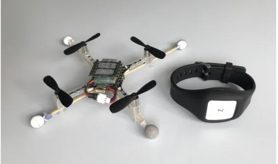
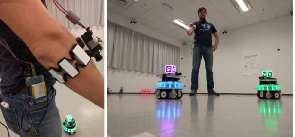
Sh-plane when the drone flies close to the eyes height, in this case, the pointing ray is almost parallel to the surface and makes it very difficult to accurately control the drone. . . 30 3.5 The hardware used in the experiments: (left) Bitcraze Crazyflie 2.0
quadrotor with retro-reflective markers for motion capture sys-tem; (right) Mbientlab MetaWearR+ IMU bracelet. . . 31 3.6 An overview of the experimental environment during one of the
sessions. The targets {T1, T2, T3} (LED beacons) are placed at the
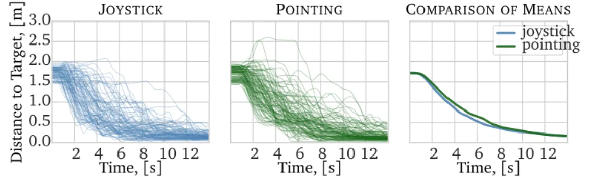
wheel hubs that are located at different heights. . . 32 3.7 Analysis of the evolution in time of the distance to the target, for
each trajectory flown; each trajectory is represented as a line; t = 0 on the plot corresponds to the t0 time of each trajectory. Left:
joystick interface (N = 90). Center: pointing interface (N = 90). Right: average over all trajectories for each interface. . . 35 3.8 Relative lengths of the trajectories flown with the pointing and
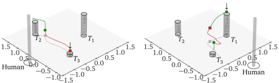
the joystick interface, normalized by straight distances between targets. The black dots and the blue crosses represent median and mean values respectively for each user (Nu= 10). The error bars represent 25-th to 75-th percentile. . . 36 3.9 Visualization of two segments of a trajectory performed with the
joystick. The short cylinders represent the targets and the tall thin cylinder represents the user. . . 36 3.10 Visualization of two segments of a trajectory performed by
point-ing. The green segment is performed with using the cylinder work-space, while the red one using the horizontal plane workspace. The short cylinders represent the targets and the tall thin cylinder represents the user. . . 37 4.1 Relative localization using a camera and fiducial markers. (Left)
An RGB-camera is mounted on top of the wearable IMU. (Right) The user points at one of the robots to select it, the robot, in turn, changes its beacon color. . . 43
xv Figures
4.2 Relative localization for multiple robots using fiducial markers.
Checker boxes depict markers; colored dashed arcs constitute the
coordinate transformation tree with the arrows pointing to corre-sponding parent frames; blue arcs are the robots’ individual trans-formation trees rooted in their odometry frames; red arcs are the transformations acquired during the localization process and rooted in the human frame. The long-dashed curves are the robots’ trav-eled paths. . . 44 4.3 Distribution of the euclidean position errors "e (blue dots and
bars) on a map of the experimental environment. Large black dots represent the targets, the numbers are the target labels, and the star is the location of the human. The robot is located at target 9 and oriented towards target 4. . . 46 4.4 Scatter plots of the position errors. . . 46 4.5 (Left) The user triggers interaction. (Center) All nearby robots
start moving along different paths, and the operator keeps point-ing at the desired robot. (Right) After a few seconds, the system identifies the target robot and reconstructs the transformation be-tween the robot and the user; then the interaction can continue in an application-dependent way, e.g. landing at a precise spot. . 48 4.6 Experimental setup for data collection (ground truth): two
trajec-tories (circular and triangular) are represented by thin orange and blue lines, the operator positions for each of the five sessions are represented by the circular and triangular markers. Labels iden-tify the respective sessions in Figure 4.8. . . 52 4.7 Simulated odometry estimates of the drone trajectories: (blue/solid)
perfect ( = 0), i.e. ground truth; (orange/dashed) good ( =
0.001); (green/dot-dashed) bad ( = 0.005), (red/dotted)
terri-ble ( = 0.015). . . 53
4.8 We report one row for each value of the VO noise 2 {0.001, 0.005, 0.015}, and one column for each session. Each plot reports the
distribu-tion (box) of the error metric ( y axis) as a funcdistribu-tion of the duradistribu-tion of the trajectory (x axis) over 20 replicas. Results for ideal odom-etry ( = 0) are indistinguishable from for plots with = 0.001 (first row) and are therefore not reported. . . 57 4.9 Implementation of the proposed method in a real-world experiment. 58 4.10 A prototype of the system that uses a commodity smartphone
(Ap-ple iPhone 8) to dynamically track coordinate transformation be-tween the user and the drone (Crazyflie 2.0). . . 61
xvi Figures
5.1 Selecting (left) and commanding (right) robots using natural speech accompanied by pointing gestures. . . 64 5.2 The success rate in identifying the correct robot among two (see
text). 100 replicas per bar. Error bars represent 90% confidence interval. . . 67 6.1 The scheme of the experimental environment: targets are fixed at
the corners of a square with a 3.6 m edge (one tile is 0.6 m). The human position is fixed at the center. The sequence is defined by arrows and starts at target 1. . . 73 6.2 Statistical analysis of the landing error metric (N = 60 for each
interface). . . 76 6.3 Visualization of all trajectories (N = 120) flown with joystick (left)
and pointing (right) interfaces. Fixed human position is denoted by a star. Targets 1–4 are denoted by a thin cross (clockwise from top-left). . . 77 6.4 Statistical analysis of the time to target (left) and trajectory length
metrics (right) (N = 15 for each interface and segment). . . 78 6.5 Comparison of all trajectories flown from target 1 (left) to target
2 (right) for joystick (blue, N = 15) and pointing (green, N = 15) interfaces. . . 78 6.6 Evolution in time of the distance to the target, for each trajectory
flown: (left) joystick interface (N = 60), (center) pointing inter-face (N = 60), (right) average over all trajectories for each interinter-face. 79 6.7 Interaction using pointing gestures with a slow-moving robot equipped
with a laser turret for real-time visual feedback. . . 80 6.8 Effects of real-time visual feedback on pointing accuracy. . . 81 7.1 A prototype of the pointing-based smart lights interaction system
Tables
3.1 Performance per subject (median and mean over all segments) . . 37 4.1 Trajectory estimation errors due to the visual odometry model.
For each trajectory duration (row), we report the average over all experiments of the following measures (all in meters): the ground truth trajectory length and extent (i.e. the distance between its two farthest points); the mean and maximum error due to visual odometry for = {0, 0.001, 0.005, 0.015}. . . 54
Chapter 1
Introduction
Figure 1.1. The user controls a miniature drone (Bitcraze Crazyflie 2.0) with
pointing gestures acquired with a wearable IMU sensor (Mbientlab MetaMo-tionR+) placed on the user’s wrist.
Human-robot interaction (HRI) is a large field that covers many areas of hu-man knowledge. It lies at the intersection of robotics, cognitive sciences, and computer sciences. It involves analysis of human-human interactions, human and robotic perception, design of hardware and software systems.
The interaction between humans involves multiple modalities, such as speech, gestures, facial expressions, gaze, and physical contacts. In human-robot inter-action, it is common to differentiate interaction as physical (pHRI) and cognitive
2
(cHRI). An overview of these fields are given, respectively, by Bicchi et al. [2] and Breazeal et al. [6]. pHRI involves physical contacts between the agents, and thus, studies interaction forces and control stability, dominance distribution in multi-agent setups, haptic feedback, etc. A typical example of physical human-robot interaction would be the exoskeletons (‘wearable human-robots’) which augment the force of a wearer either to enhance their natural abilities or for rehabilita-tion purposes. In contrast, cHRI deals with a higher-level interacrehabilita-tion, where the agents only exchange information, but not forces. The information in the cog-nitive interaction case can be conveyed in the form of concepts, e.g. directions, locations, and common objects (‘a can of soda’). This PhD work focuses on cHRI and thus will further refer to it simply as HRI.
In the past years, a considerable amount of robotics research has been de-voted to gesture-based human-robot interaction. The two types of gestures gen-erally considered are hand and arm gestures. While hand gestures are usually associated with iconic commands or emblems, pantomimes and sign language, arm gestures are more often associated with pointing or deictic gestures [52; 72]. Because pointing requires to move both the arm and the hand (the index finger is extended and the arm is straight), many works that use the term hand gestures presume the use of arm gestures as well and thus both notions are often used interchangeably.
Depending on the type of interaction and the type of information to be com-municated to a robot the gestures can be either static or dynamic, could accom-pany speech or can be used on their own. For example, periodic dynamic ges-tures, like arm or hand waving, could be used to attract a robot’s attention [53]; pointing gestures could provide a context for the speech commands by linking deictic pronouns, e.g. ‘that’ and ‘there’, to a spatial entity, such that a cumber-some utterance like ‘Go three meters forward, then five meters to the left’, can be simply replaced by ‘Go there’ and the pointing gesture.
Pointing to entities or positions in an environment is a skill acquired within the first year of human life [9] and an effective device that humans use all the time. Thus, pointing is of particular interest to the robotics community: it allows the human user to intuitively communicate locations and other spatial notions to robots. Some of the tasks that can be efficiently solved with pointing gestures are pick-and-place [33], object and area labeling [79], teaching by demonstration [73], point-to-goal [84], and assessment of the joint attention [8].
In this work, we are looking for efficient ways to interact with robots using pointing gestures. We focus on point-to-goal applications for mobile flying and ground robots: the user points at a location in 3D space and the robot moves
3
there using its on-board intelligence. This interaction pattern suits well many applications: it can be used for transporting goods with cargo robots in ware-houses, indicating parking spots for autonomous vehicles, specifying areas of interest for inspection drones, indicating a precise landing spot for a delivery drone, or even for calling a cleaning robot to wipe a spill on the floor.
Research problem
A typical approach to human-robot interaction using gestures would be to equip the robot with a computer vision sensor, e.g. a stereo vision or a structured light camera. In this case, the robot has to actively look for a human in the environment, track them, try to recognize if they want to initiate the interaction, and then wait for commands to follow. Once the command is issued the robot may need to look away from the user to perform the given task, and therefore will not being able to receive new commands anymore.
We follow an alternative approach that does not require the robot’s atten-tion. It is based on the use of compact wearable inertial measurement units (IMUs) that provide an accurate estimation of their own orientation with respect to an arbitrary absolute reference frame. This type of sensors is ubiquitous and nowadays present in almost all modern smartphones, smartwatches, and fitness trackers. One or multiple IMUs are placed on the user’s arm or held in the hand and provide the direct measurements of the arm’s pose. The necessary compu-tations are then performed on a device worn by the user, e.g. a smartphone or a smartwatch, such that the robot receives only high-level commands. The com-mands are communicated to the robot via a wireless link and do not require a robot’s visual attention.
Both sensing approaches have their pros and cons. Although vision-based methods operate within a limited field of view and range, they allow the system to gather reacher information about the user’s posture, e.g., they can capture po-sitions of all visible human joints at once without adding new sensors. Moreover, the robot-centric vision systems estimate positions of the joints directly in the robot’s coordinate frame, and thus, require no additional localization of the user relative to the robot. On the other hand, robot-centric vision poses an essential problem for gestures aimed directly at the robot or locations very close by: the arm axis gets nearly perpendicular to the image plane and makes it impossible to estimate the pointed direction accurately. This peculiarity makes pointing-based robot selection and continuous position control problematic.
4
and is suitable for a broader range of environmental conditions. It demands less computational power; however, because inertial sensors estimate accurately only rotation, it is necessary to use human body kinematics to calculate joint positions. In turn, it requires the re-localization of the human every time they move away from their initial position. In this work, we propose and demonstrate several efficient ways to deal with these limitations.
Regardless of the approach used to sense gestures, there are several research challenges one needs to address to successfully implement an efficient human-robot interaction system based on pointing.
Human perception. The way people point at objects, places, and other people
depends on the context, social and physiological peculiarities of an individual: for example, if a person intends to pinpoint a small object, an object far away, or a single object that cannot be unambiguously identified among other similar objects, then the person is likely to point with a straight arm using the index finger; on the contrary, if the object is big and close by, the person may point with the entire hand and the arm bent at the elbow.
To better understand how pointing gestures can be captured by sensors and how can we infer pointed locations and directions from this data, we study the works in experimental psychology. We then choose a human pointing model that would allow us to map a set of input parameters to a pointed location or object. The input parameters could be: a human posture, i.e. relative positions of the human limbs; visual perception peculiarities of an individual, e.g. handedness and eye dominance; cognition; context and environment, e.g. size of a pointed object and a distance to it.
We report a state of the art in psychology and human-robot interaction re-search in Chapter 2.
Estimation of pointed directions and locations. Because it is not always
possi-ble (or practical) to capture all input parameters of human pointing models us-ing a specific technology, e.g. wearable inertial or computer vision sensors, it is necessary to derive appropriate approximated models. This strand of research, therefore, deals with practical implementations of human pointing models in human-robot interaction systems. Once the pointed direction is found we need to relate it to an object or location in the surrounding environment, for example by intersecting a pointing ray with a 3D model of the workspace.
In Chapter 3 we define the human pointing model used in our research— eye-finger model. We formally define its parameters and kinematic relations it is
5
based on. Then, we discuss the ways to find a pointed location in the surrounding environment. Finally, we describe our main contribution to this field: a practical
approach to defining 3D target locations for robots freely moving in 3D space. We
validate that approach for a quadrotor control in a user study.
Relative localization. Pointing gestures inherently define locations in the user’s
local frame which might be unknown to a robot. Hence, it is necessary to define a common reference frame between the user and a robot. In other words, the user has to be localized with respect to the robot. This research direction considers various localization techniques appropriate for human-robot co-localization.
In Chapter 4 we consider several practical approaches to the problem of rel-ative human-robot localization. We formally define the necessary coordinate transformation relations and show how each of the proposed methods allows acquiring the coordinate transformation between a user and a robot. Our main
contribution is a motion-based localization method that relies on human
percep-tion: the user points at a moving robot and keeps following it with their arm
for a few seconds; the system compares motions of the robot and the user and estimates a relative coordinate transformation between the two.
Robot selection and identification is required whenever an operator has to
deal with more than one robot, or more generally when the number of operators is not equal to the number of robots. Even when there are a single operator and a single robot, there is a question: how would the operator start an interaction? We study various practical solutions to these problems that are based on push-buttons, voice control, and gesture recognition.
In Chapter 5 we show various ways to engage a robot and a user. In particular, we demonstrate how our relative localization method described in Chapter 4 can be efficiently used to solve this problem.
Efficient interaction feedback. In the process of human-robot interaction, the
user gives commands to a robot and needs to be sure they are received and understood as intended. The interaction feedback plays an important role in this process and allows both humans and robots to immediately correct their actions. In Chapter 6 we discuss various ways to improve the interaction performance using appropriate feedback.
During this work, we also attempted to come up with realistic implementations of interfaces being designed. For this, we searched the most suitable technologies
6 po !o pt r {R} {H} {H} {R} {H} Chapter 4 Chapter 3 Chapter 5 Chapter 6 Thr =?
Figure 1.2. Thesis overview: Chapter 3 describes the human pointing model
adopted in this work and estimation of pointed locations in 3D space;
Chap-ter 4 presents various localization techniques and our method of relative
lo-calization from motion; Chapter 5 discusses robot selection and identification methods, including the one based on our relative localization approach;
Chap-ter 6 demonstrates various types of feedback: a continuous real-time feedback
provided by the robot motion itself, colored lights, and a haptic feedback on a wearable sensor.
that are available on the market today or anticipated to appear in the near future. To validate the usability of the resulting interfaces we conducted qualitative and quantitative user studies.
Finally, in Chapter 7 we draw conclusions, discuss limitations of the proposed methods and ways to improve them.
A graphical overview of our core research contributions is presented in Fig-ure 1.2.
7
Contributions
In this section, the author summarizes his personal contributions to state of the art. These contributions span the Chapters 3–6 where they are described in de-tail.
Chapter 3: Estimation of Pointed Locations The author proposes a simplified
human pointing model that uses a single inertial measurement unit (IMU) to estimate pointed locations both in 2D and 3D space. The main contribution of this chapter is a pragmatic method to specify targets in free 3D space that re-solves an inherent ambiguity of pointing—mapping of a two-parameter pointing ray to a three-parameter target location. The author proposes to use a set of well-defined virtual workspace surfaces to constrain the robot’s motion. In par-ticular, for improved legibility of the system’s state, the author proposes surfaces of two shapes: a vertical cylinder centered at a user’s location and a horizontal plane. Each shape is defined to pass through a current robot position: this way, knowing the type of selected workspace shape and seeing the robot, the user can easily visualize the workspace surface and predict the trajectory of the robot. The method is validated in a user study.
Publications The idea to use wearable inertial sensors to estimate pointed
locations was first exploited in a workshop paper [25] and further used in a conference paper [24]. In these works, we started with a sophisticated wear-able system that included two IMUs: on the upper arm and on the forearm. The pointed locations in these works were estimated as an intersection of the pointing ray (shoulder-finger pointing model) with the ground plane. The main problem of such setups was different drift rates of the two IMUs that resulted in a distorted kinematics chain and the need for re-initialization of the system. The next iteration of the system was simplified to use a single IMU on the upper arm for pointing reconstruction, while the second IMU was used for the detection of pointing events. The author compared the performance of the developed point-ing interface against a joystick interface in a drone landpoint-ing task in [28; 30]. The method to define the robot’s locations on a 2D horizontal plane was described in detail in [29], while the method to define positions in free 3D space is presented in [32]. In both cases, to estimate pointed direction we used the eye-finger point-ing model.
Chapter 4: Relative Localization The author considers, implements, and
8
(1) using a global reference frame, (2) using fiducial markers installed on each robot and a camera on the user’s forearm, (3) using a predefined heading (point-ing at robot from its back), and (4) localization from motion—the main contri-bution of this chapter to the state of the art. The method (4) requires the user to point at and keep following a moving robot for a few seconds: the system is then able to estimate a relative coordinate transformation between the user and the robot.
Publications We used the method of a global reference frame in our first
work (workshop paper) in [25]. We then presented the idea of using fiducial markers in a conference paper in [24], and further studied its accuracy in a work-shop paper in [26]. Finally, in [27] we presented our main contribution of this chapter—relative localization from motion.
Chapter 5: Robot Selection and Identification In this chapter the author
de-signed and implemented several robot selection methods. In particular, a combi-nation of speech utterances and pointing gestures were used for the selection of individual and groups of robots, e.g. “You and another 2!”. In this case, pointed locations are compared with known coordinates of available robots and used for their identification, while the speech is used as a selection trigger. Because cloud-based speech recognition services that we were using introduced a significant lag into the interaction process and were difficult to scale, we studied alternative se-lection methods. The author implemented a method based on fiducial markers with unique identifiers that allowed to instantaneously determine a robot the user was pointing at and therefore trigger selection. The main contribution of this chapter to state of the art is a robot identification and selection method based on relative localization from motion approach that is described in Chapter 4: as-suming several robots are moving on unique trajectories, the user points at one of them and keeps following it for a few seconds, the system then compares rel-ative localization residual errors and selects a robot whose trajectory yields the lowest error.
Publications We presented the speech-based selection method in the
work-shop paper [25] and further elaborated it in a conference paper [24]. The lat-ter paper also describes the robot selection method based on fiducial markers. In collaborative work with Broggini et al. [7] we proposed and implemented a method that uses a 1D convolutional neural network to detect pointing events: once the pointing gesture is detected, robot identification can proceed by com-paring a pointed-at location with robots’ positions. The main contribution of this chapter—robot identification method using the relative localization from motion
9
approach—was presented in a conference paper [27].
Chapter 6: Efficient Interaction Feedback Throughout this PhD work the
au-thor aimed at improving the usability of proposed methods by providing ade-quate feedback to the user. In this chapter, the author describes various types of feedback: voice, lights, vibrations, and robot motion itself. The main con-tribution of this chapter to the state of the art is a user study on the effects of continuous visual feedback during the pointing process. We show that a con-tinuous control of the robot’s position allows the user to timely correct for any inaccuracies induced by a simplified human pointing model and a drift of wear-able inertial sensors.
Publications We designed and implemented a system with voice feedback
in [24] where it is used for acknowledgment of user’s commands. In the same paper, we also used colored lights installed on robots to show when a robot is selected. In [31; 30] we programmed a drone to “jump” in the air to show it has been engaged with the user. In [29] we describe our main contribution to the state of the art—a user study that shows the importance of real time visual feedback on pointing accuracy.
Chapter 2
Literature Review
Since pointing gestures are such a compelling solution to many human-computer and human-robot interaction problems, significant research efforts have been devoted to this topic.
Modern human-robot interaction developed mainly from the teleoperated ro-botics and the human-computer interaction fields. Arguably, one of the most fa-mous and pioneering works in human-computer interaction is “Put-that-there” by Bolt [5]. In that work the MIT Architecture Machine Group’s “Media room” was staged to perform multi-modal interactions where the user should have used speech commands in conjunction with pointing gestures to manipulate virtual objects on a screen1. Bolt argues that this way the virtual interface is implicitly
merged into the real world and creates a continuous real-space interaction envi-ronment. Moreover, the speech commands supported by pointing gestures can be significantly simplified by replacing the object’s and location’s names with the pronouns like ‘that’ and ‘there’. In this case, Bolt argues, the user even do not have to know what the object is or how it is called.
In the following sections we study the related works from experimental psy-chology, haptics, human-computer and human-robot interaction fields. We fol-low the same order of the research topics that we defined in the introduction, in Chapter 1.
2.1 Human perception
Deictic gestures, and in particular pointing to entities or locations in environ-ment, is an innate and a specific to human species skill [9]. Pointing is effective
1https://www.media.mit.edu/speech/videos/Putthatthere_1981_edited_full.mov
12 2.1 Human perception
means of communication and interaction that humans use all the time. It has a dialogic nature in that it requires a joint attention of the interacting people on the object of pointing. Butterworth studied the development of pointing compre-hension and production in babies and indicates that canonical pointing2emerges
by the end of the first year of life. However, at this age infants’ abilities to un-derstand what object is being pointed at are somewhat limited: babies generally fixate on targets only if the latter have salient features, such as when the objects are in motion. By the 18 months babies are able to localize the target without additional cues. Butterworth argues that it become possible thanks to eventual development of joint visual attention when babies are able to extrapolate the adult’s head, gaze or pointing arm direction.
B A
Figure 2.1. Pointing
misinter-pretation. Subject believes to point at A, while observers in-terpret she/he points at B. Figure has been adapted from the orig-inal work of [36].
The ability to understand pointed locations is even limited in adults. Herbort and Kunde experimentally shown that locations meant by a pointer are different from that are inter-preted by an observer [36]: one group of sub-jects (pointers) was asked to pointing at ticks on a vertical ruler, while the goal of the other group (observers) was to guess these pointed locations. The experiment has shown that most of the observers were indicating positions higher than they were meant by the pointers (Figure 2.1). Herbort and Kunde explain this phenomenon by the difference in geometrical
rules that guide the production and interpretation of pointing gestures. While in the pointing production subjects tend to keep pointing finger close to the line of sight—but avoid occluding the target—observers interpret the pointing direction by extrapolating the long axis of the pointing arm.
Works in psychology research on pointing gestures show that the tip of the index finger of a pointing arm tend to lie close to the line of sight between the human and the object being pointed at when pointing with a straight arm [76; 36]. The human perception model based on this observation is often referred to as the eye-finger model. The ‘eye’ in this model is meant to be a dominant eye3
of an individual. Khan and Crawford shown that the ocular dominance is not a static concept and depends on the relative position of the eyes with respect to the object they are looking at [43]. The pointing with a straight arm is typical
2A gesture with index finger and arm extended, palm down, other fingers curled.
3Ocular dominance is the tendency of a brain to prefer visual input from one eye to the other
13 2.1 Human perception
when the pointed target is far away or when the person is trying to be precise. However, when the targets are relatively close, people tend to bend the arm at the elbow [44]. In this case, the eye-finger model does not work anymore and the pointing is better described by the elbow-finger model [44].
In robotic applications of distal pointing we are primarily interested in de-termining target locations the user wants to indicate; therefore, this work will further focus on pointing production. To understand the extent of the application of pointing gestures we are also interested in intrinsic limitations of human mo-tor control that sets the lower bound of pointing accuracy and the time necessary to perform a pointing gesture.
Motor control of the arm relies on two major senses: proprioception4 and
vision [22]. One of the early works on pointing production by Taylor and
Mc-Closkey shown that vision plays an important role in this process and dominates proprioception [76]. The authors compared the pointing of blindfolded subjects with those using vision and found that in the former case the pointing direction coincides with the shoulder-finger line; however, if the subjects were pointing first using vision and then were blindfolded the influence of visual perception remained for some time and influenced the pointing direction [76]. The differ-ence between visually-monitored pointing and the blindfolded one was also later confirmed by Wnuczko and Kennedy, where the authors shown that the pointing guided by vision results in higher arm elevations as compared to the one guided only by proprioception [83].
Research in neurophysiology shows that vision is likely to be used as a source of information for generating spatial plans for movements towards visual tar-gets within an extrinsic coordinate system, while proprioception is crucial for implementing these kinematic plans by transforming them into control forces of individual muscles [67]. According to the estimations of Sober and Sabes the first stage of motor control planning is dominated by visual information (80%), whereas the second stage relies mostly on proprioception (70%) [70]. These two stages loosely resemble an approach often used in robotics; there, a high-level trajectory planning in Cartesian-space is followed by the trajectory execution in joint-space using inverse dynamics of the robot.
According to Tan et al. the upper bound of human force control bandwidth is about 20 Hz [75], at the same time intrinsic involuntary oscillations (tremor) of the pointing hand have two dominant frequency peaks at 2–4 Hz and 8–12 Hz [54]. Morrison and Keogh analyzed tremor frequencies in a pointing task with
4Proprioception is the perception of positions and movements of the body segments in relation
14 2.2 Estimation of pointed locations
and without precise visual feedback and found that the tremor oscillations ampli-tude significantly increase when the subjects are asked to point at a small target (angular width of 0.42 ) using a laser dot [54].
The inherent accuracy of the human arm was studied by Tan et al., they mea-sured the arm joints angle resolution for shoulder, elbow, and wrist, and found that proximal joints are more accurate than distal ones. While the average an-gle resolution of the shoulder is 0.8 , the average resolution of an index finger (MetaCarpalPhalangeal joint) is much larger and equals to 2.5 . Interestingly, the resolution of the joints increase not just the faster they move, but also if the movements are active (voluntary) as compared to the case when they are moved by external apparatus [40].
There is also a distance limit at which humans with normal eyesight can per-ceive remote targets, e.g. robots. According to Nancel et al. the angular size of a target should be more than 10= 1
60 ⇡ 0.017 [57]. That means that the
max-imum distance at which the operator of a typical drone (circumference 30 cm) could see it is 1 km. Taking into account the challenging background of outdoor environments this number probably will be much smaller. As can be seen, the visual acuity is one magnitude better than the resolution of the pointing arm. However, these numbers give the upper bound distance at which a direct line of sight interaction can occur.
2.2 Estimation of pointed locations
The human perception models defined in psychology research do not put any constraints on the input parameters; however, in the engineering applications, not all the input parameters are possible (or practical) to acquire. This research area, therefore, attempts to approximate comprehensive human perception mod-els with simplified modmod-els based on application constraints.
The estimation of pointed locations can be split into two sub-tasks: (1) esti-mation of the direction of pointing (usually in the form of a ray), and (2) estima-tion of the intersecestima-tion of the pointing ray with the environment.
2.2.1 Pointed directions
In HCI and HRI research the two classes of pointing direction estimation methods can be distinguished: head-rooted and arm-rooted. The head-rooted techniques consider a pointing ray that originates somewhere within the head: from a dom-inant eye [64], cyclops eye [49], or head centroid [58; 80]. Arm-rooted methods
15 2.2 Estimation of pointed locations
assume the ray originates from a point laying on the pointing arm: at shoulder, elbow [58; 15; 48; 44], wrist [33] or index-finger [48]. The pointing direction is then defined by the second point, sometimes called direction point, that lies on the arm. For the head-rooted methods, this point is either a centroid of the hand or a tip of the index finger, while for the arm-rooted techniques the second point can be at the elbow, at the wrist or hand, or at the tip of the index finger.
In HCI these methods are often referred to as ray casting or ray pointing techniques. The main applications of pointing in HCI field are the interaction with graphical user interfaces (GUIs) on very large displays [5; 41; 12], 3D im-mersive environments [63], and recently interaction with smart environments [50; 18; 64; 42]. The most popular pointing techniques in HCI are: a laser
pointer [41] and an image plane manipulation [63; 41]. The laser pointer
tech-nique refers to any handheld device that can report its orientation which is then used for determining the pointing ray. Among these types of devices are com-mercially available controllers such as Nintendo Wiimote, HTC Vive Controller, and Oculus Touch. The last two are specifically designed for interaction with virtual reality (VR) environments. The image plane manipulation is an approach to manipulate distant objects as if they are within arm’s reach5. Essentially this
type of technique is directly related to the eye-finger pointing model because it also uses one’s line of sight to indicate an object.
Based on combinations of the root and direction points, the taxonomy of the pointing models includes head-hand, eye-finger, shoulder-elbow (upper arm), elbow-wrist (forearm), elbow-hand, and index-finger models.
2.2.2 Pointed locations
Once the pointed direction in the form of a ray is found a pointed location can be estimated as an intersection of the pointing ray with the environment. While a 3D model of a virtual environment is known in advance, a model of a real environment has to be acquired by some means, for example with computer vision sensors.
In HCI the problem of finding an intersection point is often circumvented by means of relative pointing techniques with additional visual feedback (i.e. a cursor on the screen). This type of interface is resembling a computer mouse and does not require the intersection point. Although relative pointing can be quite efficient it requires the system to use motion indexing (or ‘clutching’) in order to map the range of motion of the physical device to the workspace of
16 2.2 Estimation of pointed locations
the environment. For example, when the computer mouse reaches the border of a tabletop the user has to disengage the mouse by lifting it above the surface and then reposition the device in the physical environment. On the contrary, absolute pointing devices map the entire physical range of motion to the entire workspace; this technique, however, requires the system to know the coordinate transformation between the user (or pointing device) and the screen.
In HRI, instead of a cursor or elements of a GUI, the user needs to control a robot in the real environment, for example, to reposition it or change its config-uration. Therefore, for this to work, we have to establish a common reference frame between the user (and subsequently the pointing device) and the robot.
2.2.3 Pointing correction
While dealing with continuous space of possible pointed targets, the accuracy of pointing gestures may have a significant impact on the interaction performance and cannot be neglected. The simplified models (as compared to the actual hu-man perception models) reduce the accuracy of the estimated locations and di-rections and has to be carefully assessed. There are three main sources of errors that contribute to the final accuracy: (1) intrinsic characteristics of human per-ception and motor skills, (2) inaccuracies of gesture interpretation model, and (3) external measurement errors. The first error is characterized as the repeata-bility of pointing gestures, i.e. how well can a human point at the same target over and over again. The second error is defined as a difference between the es-timated target location and the location human intended to point at. Finally, the external measurement errors are those induced by misplacement of the sensors, their noise, etc.
These errors can be reduced by means of additional visual feedback, similar to the cursor on a screen [5], a better gesture interpretation model, and a thorough sensor calibration. However, perhaps a more practical approach is to learn a pointing model directly from the observations. Droeschel et al. utilized Gaussian Process Regression (GPR) to train function approximator that maps human body features extracted from a time-of-flight depth image data to a pointing direction [15]. Authors compared the accuracy of their GPR-based model with the trivial line-based models, i.e. head-hand, elbow-hand and shoulder-hand, and shown significant improvement in the pointing accuracy: 0.17 m vs. 0.39 m (head-hand model) average distance error. One of the important conclusions made by Droeschel et al. is that the trivial line-based methods can be inadequate for certain ranges of target directions: while the GPR-based model produced evenly distributed errors, the line-based models shown significant bias at certain targets.
17 2.3 Relative Localization
A work by Mayer et al. follows a similar approach, but instead, they use user-, pose-, and distance-independent quadratic polynomial to correct systematic dis-placements of pointing gestures [48].
2.3 Relative Localization
An important aspect of absolute pointing gestures is the necessity of a common point of reference between the human and the robot. The gestures are captured in the sensor’s coordinate frame, but eventually, have to be interpreted by the robot in its own frame. In the case of external sensing, the sensors are often installed directly on the robot and thus the frame transformation is not neces-sary, i.e. acquired gestures are already in the robot’s frame. However, wearable sensors, e.g. IMUs, report the data in an arbitrary inertial frame and the mea-surements have to be converted first to the human’s frame and then to the robot’s frame.
Localization is an essential part of any robotic system: it is used for relating a robot pose to a working environment, objects in it, or other agents (including humans). Localization of a rigid body, such as a robot, in 3D space, assumes the knowledge of its full 6D pose: three translations and three rotations with respect to x-, y-, and z-axes. Some methods allow one to acquire the entire pose, while other methods could only provide partial information, e.g. a 3D position or a 3D orientation. In general, all localization methods can be grouped into direct and indirect methods.
2.3.1 Direct methods
Direct methods assume that the position of one agent is estimated directly with respect to another agent, using, e.g., triangulation or multilateration of a radio [81], optical, or sound signal [68].
These also include vision-based methods, such as localization using passive [19; 21] and active [17] markers, known geometry, or other visual features of the agent [20]. For example, when it is a human to be localized, features like natural skin color [58], face [55], or even legs [62] can be used.
An interesting example of the partial direct localization is a method imple-mented in a commercial toy robot BB-8 by Sphero [71]. The robot is able to move on a horizontal flat surface and is controlled by a wearable bracelet-like interface fitted with an IMU to provide velocity commands: the user can perform a push-like gesture with their arm along a given direction to move the robot.
Be-18 2.4 Robot selection and identification
cause the robot is bound to a horizontal plane and control in velocity space, it requires localization of only one degree of freedom—a relative heading between the human and the robot, i.e. a relative rotation around z-axis. When the user initiates the localization procedure, a single light on an LED ring on the robot circumference turns on: at this point, the user can control which LED is illumi-nated on the ring by twisting their wrist. Once the user aligns the illumiillumi-nated LED with the pointed direction, they press a button to complete the calibration procedure. Now, the heading of the user’s arm as measured by the IMU can be converted into the robot’s frame.
2.3.2 Indirect methods
These methods assume the two agents are localized with respect to a common reference frame and thus a coordinate transformation can also be recovered be-tween the agents.
A common reference can be established using geographical coordinates using a global positioning system (GPS) [16], or using techniques that are suitable for indoor use, such as optical motion capture systems like Optitrack, or ultra-wideband (UWB) localization systems [81; 35].
An alternative approach is a co-localization of the agents [69] that individu-ally perform simultaneous localization and mapping (SLAM) of the same envi-ronment. By finding correspondences between the maps produced by each robot it is possible to estimate coordinate transformations between the agents.
In the indirect methods, inertial sensors are used in conjunction with vision sensors to find better estimates of the egomotion of the system for the SLAM task [45].
2.4 Robot selection and identification
When there are multiple robots, and possibly multiple operators, that each need to control their own robot, the system must provide a way to select individual robots among a group. The ability to select a robot is also useful for a single robot / single operator case: it allows one to engage with the robot and trigger the start of an interaction.
Couture-Beil et al. developed a computer vision pipeline that uses an orien-tation of the user’s face to estimate which robot the user wants to engage with [14]. Another work from the same research group by Pourmehr et al. extends that approach with a multi-modal interface based on natural speech where the
19 2.4 Robot selection and identification
user can engage with individual robots and groups of robots by using indirect speech references, e.g. “You two! Take off!” [65].
Monajjemi et al. used periodic waving arm gestures to engage with a drone that flies far away (20–30m), once the robot’s attention is attracted it approaches the user and waits for another, short distance, commands such as taking a selfie [53].
Robot selection can also be performed indirectly. Cacace et al. proposed a system that implicitly selects a robot from a pool of available robots that are suitable for a particular mission. The availability, in this case, can be determined based on various parameters, for example, the battery level of a quadrotor [10] and its capabilities. Wolf et al. shows a simple yet effective way to select robots within a fixed group by iterating through them using an arm gesture [84].
Pointing gestures are particularly intuitive for the robot selection task. Nagi et al. used a distributed consensus protocol for a swarm of robots equipped with vision sensors to estimate which of the robots is being addressed by human point-ing [56]. Interestpoint-ingly, a robot that is bepoint-ing pointed at has the worst view of a pointing hand: in this case, the finger and the hand coalesce and are perceived as a single blob. That means the closer the robots are in the swarm to each other the more difficult for them to differentiate which one of them is being pointed at—a familiar experience we have from our daily lives.
Inertial sensors allow one to have a trivial robot identification system that is based on a mere comparison of pointed locations with the coordinates of the robots themselves. However, engaging a robot immediately when such compar-ison succeeds may be undesirable as an indicated point in the environment may cross through many other robots before reaching the one intended by the opera-tor. For this reason, it is necessary to trigger the interaction explicitly, only once the operator is convinced to select the pointed-at robot.
Among the ways to detect pointing events are fixed time delays [33; 13], using a hand gesture of the other (non-pointing) arm [38; 78], or detecting the phase of a pointing arm gesture [58; 15; 61; 7].
Using two wearable sensors setup Broggini et al. trained a 1D convolutional neural network (CNN) to predict the probability of an arm gesture to be a point-ing gesture [7]. Once the probability passes an arbitrary threshold the gesture is considered to be pointing and the system can engage the robot and the operator.
20 2.5 Efficient interaction feedback
2.5 Efficient interaction feedback
A feedback signal is an important element of human-robot interaction as it allows both humans and robots to immediately correct their actions.
There are various ways robots could communicate their state to a user: sounds and speech, lights and graphical displays. The state could also be encoded in the robot’s behaviour by adjusting its trajectories.
Feedback sounds and lights are used by many commercial mobile robots. For example, the Parrot Bebop 2 drone would play a distinctive sound pattern and blink its light after a collision, which signifies the system has to be restarted. A toy robot StarWars BB-8 uses the light on its LED-ring during the adjustment of the relative heading between the robot and the wrist controller ForceBand worn by the user; the ForceBand would also play various sounds when it recognizes appropriate control gestures.
For their simplicity lights are also a popular choice in the HRI research. Szafir et al. used a circular strip of light-emitting diodes (LEDs) on the circumference of the drone to study the ways of communicating motion directions to the user. The authors tested four feedback patterns, namely: blinker—a metaphor of car turning signal; beacon—searchlight of a lighthouse; thruster—a metaphor of the flames from the engine of an aircraft; gaze—represent two stripes of lights and mimic eyes. The survey among participants shown that the gaze and blinker metaphors have the best ability to communicate the robot’s motion intentions [74].
Monajjemi et al. installed an RGB LED strip on the front side of the drone to communicate its intent to the user. The drone is able to detect a waving user, approach them, and follow hand gesture commands, e.g. take a photo (selfie) of the user. The drone is able to communicate such states as search, approach, being lost, camera timer countdown, etc. [53].
Cauchard et al. studied the ways a drone can communicate its state through emotions that are encoded by changing the drone’s speed, altitude, and orienta-tion. For example, the drone would fly low and slow to show it is exhausted, i.e. the battery level is low [11].
Chapter 3
Estimation of Pointed Locations
Human pointing is not a trivial concept and as has been shown in related psychol-ogy research depends on many complex parameters, e.g. eye dominance. Not all of these parameters are technically easy or even possible to capture to estimate pointed locations. Therefore, it is necessary to find a reasonable approximation of the true human pointing model that is both sufficiently precise and practical to implement for robotics tasks.
This chapter describes the main concepts related to a human pointing model adopted in our research. We start by formally defining the human kinematics model and coordinate transformations that constitute it. We then define the
pointing ray associated with the chosen pointing model and show how we obtain
it from readings of a wearable inertial sensor placed on the user’s arm.
Finally, we describe the estimation of pointed locations based on these models and one of the main contributions of the present research to the state of the art—
estimation of pointed locations in free 3D space and its validation in a user study.
Estimation of pointed locations requires finding a pointed direction in the form of a ray and intersecting that ray with objects or surfaces in a given en-vironment. The mathematical notion of the ray is important as it constrains intersections in a forward direction only. Estimated locations are relative to the user and depend on the user’s posture.
3.1 Pointed directions
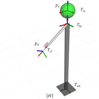
In our work we use the eye-finger pointing model that is defined by two 3D points: a midpoint between the eyes (often called a “cyclops eye”) and a tip of the index finger. We estimate the positions of these points through a minimalistic kinemat-ics model of the human body with only two dynamic parameters—arm’s pitch
22 3.1 Pointed directions Twh Ths Tse po pd Ts f {H}
Figure 3.1. Minimalistic kinematics model of the human body adopted in this
work. The red-green-blue triads show local coordinate frames that constitute the kinematics chain rooted at the human frame {H}.
and yaw. In this model we make the following assumptions: • The user stands upright and points with a straight arm;
• The eyes and the shoulder are vertically aligned, the distances from the ground to the shoulder (Lhs), from the shoulder to the eyes (Lse) and to
the fingertip (Ls f) are known and fixed.
The visualization of this model is presented in Figure 3.1.
We define the pointing ray r as a half-line originating at the operator’s eyes at point poand passing through the tip of the pointing finger at point pd (direction
point). Equivalently, this pointing ray can be defined as a vector with orientation
!o originating at point po:
r = (!o; po) (3.1)
In the arm-rooted pointing models, the orientation !o can be directly
ori-23 3.1 Pointed directions
entation of the arm does not coincide with the pointed direction and has to be calculated using human body kinematics model mentioned above.
We define the coordinate transformation tree as depicted in Figure 3.1, which is rooted at the user’s feet. Twh represents a transformation that defines human
position and orientation in an arbitrary world frame {W}, i.e. it is the coordinate transformation that brings one from the world frame to the human frame {H}1.
Similarly, Ths is a transformation from the human feet to the shoulder, Tse is a
transformation from the shoulder to the eyes, and Ts f is a transformation from
the shoulder to the fingertip. These transformations represent homogeneous co-ordinate transformation matrices but can be also viewed as a combination of pure rotation and pure translation operations. For clarity we use the latter represen-tation and define a transformation as T = (!; t), where ! is a rorepresen-tation matrix, and t = [tx, ty, tz] is a translation vector.
For clarity, in this section, we assume that human is located at the world’s origin and therefore Twh= I is the identity transformation.
We now parametrize individual transformations via predefined human body length parameters:
Ths= (I; [0, 0, Lhs]) (3.2)
Tse= (I; [0, 0, Lse]) (3.3)
Ts f = !I M U; [Ls f, 0, 0] (3.4)
where I is the identity rotation and !I M U is the rotation measured by the IMU on the user’s arm.
Using the above transformations, we define the positions of the fingertip pd
(ray direction point) and the eyes po(ray origin point) in the human frame {H}:
po= ThsTse0 (3.5)
pd= ThsTs f0 (3.6)
where 0 = [0, 0, 0] is the zero vector, i.e. the origin point.
Next, we define the direction vector v that connects the eyes and the fingertip and consequently find the orientation !o of the pointing ray r:
v = pd po (3.7)
(3.8)
1In this notation the first subscript defines a parent reference frame and the second defines a
24 3.2 Pointed locations
We now derive the yaw !yawand pitch !pitch rotations of the direction vector
v: !yaw= RPY Å 0; 0; arctanvy vx ã (3.9) vnewx = !yawex (3.10) !pitch= RPY ✓ 0; arctan vz v · vnewx ; 0 ◆ (3.11) where RPY (roll; pitch; yaw) is a function that maps roll, pitch, and yaw angles to a rotation matrix; ex = [1, 0, 0] is the x-axis basis vector, vnewx is an interme-diary unit vector along the x-axis of the coordinate frame defined by !yaw.
Finally, we can define the rotation of the pointing ray as a matrix product of the two rotations:
!o= !yaw!pitch (3.12)
Note that we ignore the roll rotation, i.e. the rotation around the user’s wrist, as it does not influence the pointed-at location in our model.
An important drawback of the proposed simplified implementation is an in-creased tangential pointing error. For example, assuming the user is pointing straight in front of them, such that the yaw of the pointing ray !yaw = 0 ; as-suming the user’s arm length Ls f = 0.69m (shoulder to finger) and the shoulder
length Lns = 0.18m (neck to shoulder), then the pointing arm heading (yaw)
angle in this case is:
!yaw= arccos0.18
0.69 ⇡15.1 (3.13)
That means the tangential pointing error at the distance of 2.0m equals 0.53m. Later, in Chapter 6, we show that this seemingly large error can be neglected if a user is provided with real time visual feedback, such as a motion of the robot itself.
3.2 Pointed locations
3.2.1 Environment surface and objects
Now that we found the pointing ray r, we need to intersect it with the environ-ment to find the location the user is referring to. In its simplest, the environenviron-ment
25 3.2 Pointed locations
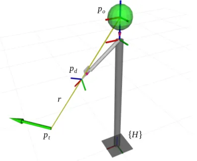
po
pd
pt {H}
r
Figure 3.2. Finding pointed location pt as an intersection of the pointing ray r with the ground plane. The green arrow represents the target pose of a robot at location pt.
represents a flat world free of obstacles and is defined by a single horizontal plane at the ground level (Figure 3.2). This is a fair assumption for many practi-cal applications, such as navigation of ground robots or landing flying robots at precise locations on flat terrain.
We define the pointed (target) location pt as:
pt= r \ S (3.14)
where S is a surface the pointing ray r is intersected with.
Note that the full pose of a rigid body, such as a robot, in 3D space is defined by six degrees of freedom: three translations and three rotations with respect to
x-, y-, and z-axes. In our model we explicitly define only the target position of
a robot, while the target orientation (yaw angle) is set implicitly along a pointed direction, i.e. equals to !yaw.
For more complex environments and tasks, e.g. navigation on rough terrain or manipulating objects, a 3D model of the surrounding world must exist. Such a model can be created with various sensors including Light Detection and Ranging (LIDAR) devices and depth cameras that many field ground and flying robots are often equipped with. An intersection of the pointing ray r with such a surface
26 3.2 Pointed locations
may result in multiple points, in this case, the one closest to the operator must be considered as the intended target point pt:
pt = arg min
p 2 r\S kp pok (3.15)
3.2.2 Free 3D space
Although the flat world model can be efficiently used to guide flying robots at fixed heights, it essentially allows one to control independently only two degrees of freedom, i.e. along x- and y-axes (with z-axis pointing up); however, one would ultimately expect a control interface for a flying robot to provide a ca-pability to change the altitude as well, or more generally—define a 3D target position in free space.
The problem that arises from this requirement is that it is impossible to un-ambiguously define pt from the pointing ray r as the target location may lie
anywhere along the ray and there is no surface to intersect with. For instance, consider the case in which the operator is pointing at the robot that flies a few centimeters above the ground and one meter in front of them. The operator then adjusts their pointing stance by slightly increasing the elevation of their arm. Does this mean that the robot should move farther from the user while staying at the same height, or that it should move up?
We approach this problem by introducing a set of virtual workspace surfaces that constrain the robot motion. We let the operator switch between these work-space surfaces to enable robot control in the entire 3D work-space.
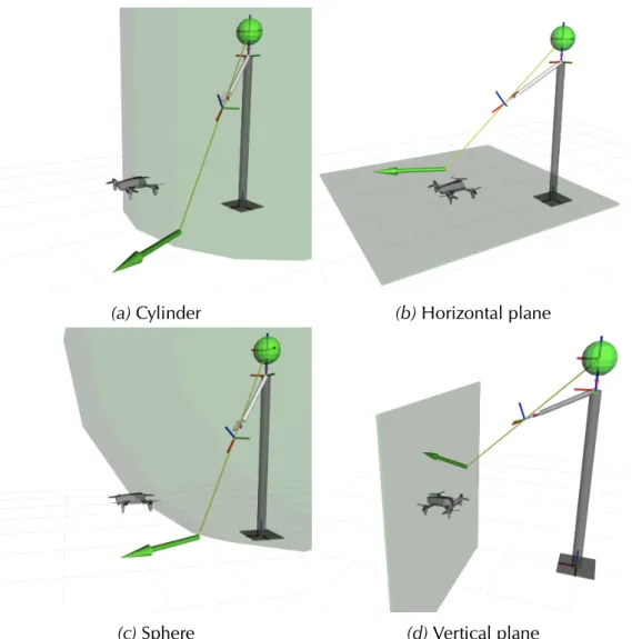
Workspace shapes
We now describe four possible shapes for workspace surfaces: cylinder, hori-zontal plane, sphere, and vertical plane (Figure 3.3). The first three shapes are defined as a one-parameter family of surfaces. When the user switches to the shape, the free parameter is set in such a way that the surface passes through the current position probot of the robot. The vertical plane shape requires to set
an additional parameter: plane orientation around z-axis.
Cylinder Scylinder with a vertical axis passing through the user’s head (po)
(Fig-ure 3.3a); the cylinder radius is the free parameter. This option allows the op-erator to control the robot’s vertical position without limitations, never affecting the horizontal distance to the operator.
27 3.2 Pointed locations
(a) Cylinder (b) Horizontal plane
(c) Sphere (d) Vertical plane