HAL Id: hal-03060152
https://hal.archives-ouvertes.fr/hal-03060152
Submitted on 8 Mar 2021HAL is a multi-disciplinary open access archive for the deposit and dissemination of sci-entific research documents, whether they are pub-lished or not. The documents may come from teaching and research institutions in France or abroad, or from public or private research centers.
L’archive ouverte pluridisciplinaire HAL, est destinée au dépôt et à la diffusion de documents scientifiques de niveau recherche, publiés ou non, émanant des établissements d’enseignement et de recherche français ou étrangers, des laboratoires publics ou privés.
Nghia H. Le, Magali Bonne, Aissam Airoudj, Philippe Fioux, Florence
Bally-Le Gall, Rémi Boubon, Diane Rébiscoul, Bénédicte Lebeau, Vincent
Roucoules
To cite this version:
Nghia H. Le, Magali Bonne, Aissam Airoudj, Philippe Fioux, Florence Bally-Le Gall, et al.. When chemistry of the substrate drastically controls morphogenesis of plasma polymer thin films. Plasma Processes and Polymers, Wiley-VCH Verlag, 2020, 18 (2), pp.2000183. �10.1002/ppap.202000183�. �hal-03060152�
When chemistry of the substrate drastically controls morphogenesis of
plasma polymer thin films
Nghia H. Le1,2, Magali Bonne1,2, Aissam Airoudj1,2, Philippe Fioux1,2, Rémi Boubon3, Diane
Rebiscoul3, Florence Bally-Le Gall1,2, Bénédicte Lebeau1,2*, Vincent Roucoules1,2*
–––––––––
1,2 Nghia H. Le, Dr. Magali Bonne, Dr. Aissam Airoudj, Philippe Fioux, Dr. Florence
Bally-Le Gall, Dr. Bénédicte Bally-Lebeau, Prof. Vincent Roucoules
1Université de Haute Alsace (UHA), CNRS, IS2M UMR 7361, F-68100
Mulhouse, France
2Université de Strasbourg, F-67000 Strasbourg, France 3 Rémi Boubon, Dr. Diane Rebiscoul
CEA, ICSM – UMR 5257 CEA-CNRS-UM-ENSCM, 30207 Bagnols-sur-Cèze Cedex, France
E-mail: benedicte.lebeau@uha.fr; vincent.roucoules@uha.fr; –––––––––
Abstract
The impact of surface chemistry on the morphogenesis of maleic anhydride plasma polymer is investigated onto silicon wafers with very well-controlled surface chemistries (i.e. native oxide, hydroxyl-rich and alkyl-rich). A particular attention is paid to characterize the early stages of growth. Two different morphologies of polymer films are obtained depending on the hydrophilic or hydrophobic nature of the substrate surface even though the chemical composition is very similar. Homogeneous and dense polymer films are formed on hydrophilic substrates due to the strong affinity of plasma species for the surface. Elongated nanostructures resulting in a less dense polymer film grows on the hydrophobic surface, which are assumed to be the result of the low affinity of plasma species.
A plasma typically contains a plethora of different chemical specieswhich can assemble into diverse solid objects having different properties [1]. This phenomenon may be interestingly exploited to control the synthesis, surface structuring, and processing of soft organic nanomaterials such as polymer thin films. During the past few decades, plasma-assisted polymer synthesis (also named plasma polymerization) drew a considerable attention not only because of its versatility and flexibility but also because of its economic and ecological advantages [2–4]. An important feature of plasma polymerization is that it enables the deposition of nanometer thin coatings on any type of substrate material and that these plasma polymers are generally smooth, compact, pinhole free and substrate-independent. Materials with a great variety of surface properties (in a chemical, physical and mechanical point of view) have been obtained [5–8]. Since a few years, scientists have demonstrated the possibility of spontaneously getting patterns within the polymer coating according to the plasma parameters used and according to the nature of the substrate [9–16]. The formation of these patterns within the film, directly linked to its morphogenesis, can have a dramatic impact on the final properties of the plasma polymer coating in terms of ageing, stability and durability. Therefore, it becomes important to have a complete understanding of the mechanisms involved in morphogenesis of plasma polymer patterns in order to control their final properties.
Micro- or nano-structured films have been obtained by using precursors such as hydrocarbons, fluorocarbons and maleic anhydride. The interest of maleic anhydride plasma polymer (MAPP) thin films lays on the high degree of retention of anhydride groups associated to their interesting reactivity (numerous potential post-modification possibilities), the numerous structures potentially formed (beads, needle-like, branched or rod-shaped structures) and the growth kinetics which can be finely controlled by playing with various experimental plasma parameters (monomer flow rate, input energy, modulated pulse time) [17–20]. As a consequence, the deposition of MAPP makes possible the surface functionalization of materials for controlled
nanopatterning [21,22], adhesion improvement [23–27], biocompatibility and biomedical applications [28–32].
The mechanisms involved during plasma polymer formation are complex. A lot of works have been dedicated to plasma chemistry in order to understand the mechanisms involved during plasma-assisted polymerization processes, most of them in the plasma phase and fewer at the plasma growing-film interface [33–37]. Morphogenesis has been less studied. However, it seems well established in the literature that morphological features are governed by the competition between surface migration of radicals towards nucleation centers, and their reaction with radicals impinging from the gas phase [9,14,15,38–40]. In other words, the key point to identify the prevailing driving forces involved in morphogenesis is to identify differences in the early stages of the plasma polymerization: i) differences in the sticking probability (i.e. differences in the probability that molecules are trapped on surface, adsorb chemically and create new chemical bonds) through the sticking coefficient and ii) differences in surface diffusion of active species (mainly radicals) through the diffusion coefficient.
The goal of this study is to demonstrate that the aforementioned driving forces involved in morphogenesis of plasma polymers are directly related with the surface chemistry of the substrate. The growth kinetics of MAPP in the early stages of deposition has been evaluated onto silicon wafers with various well-controlled surface chemistries (i.e. native oxide, hydroxyl-rich and alkyl-rich). Differences in plasma polymer properties have been followed by Fourier Transform Infrared Spectroscopy, X-ray Photoelectron Spectroscopy, Atomic Force Microscopy, Ellipsometry, contact angle measurements and X-Ray Reflectivity.
2
Experimental Section
Substrates were prepared from single-side polished silicon wafers (thickness of 380 µm, 1 × 1 cm2, Silicon Material Inc.). Before use, each silicon wafer was successively rinsed with ethanol,
(Carlo Erba, 99%), acetone (Carlo Erba, 99.8%), and chloroform (Carlo Erba, 99.9%) in an ultrasonic bath (frequency 45 kHz) during 15 min in order to remove all possible organic contaminations.
The first type of surface chemistry considered in this study was the surface obtained directly after the aforementioned cleaning procedure. This surface chemistry was referred as native oxide, SiO2. The second type of surface chemistry was obtained by exposing the cleaned silicon
wafers to UV/Ozone irradiations (UV/Ozone cleaner, Bioforce Nanosciences®) during 30 min. This process readily led to the formation of silanol groups at the surface. This surface chemistry was referred as hydroxyl-rich silicon oxide layer, Si-OH. The third and last type of surface chemistry was obtained from the Si-OH wafer after carrying out the procedure described above and a silanization step. Silanization consisting in the formation a Self-Assembled Monolayer (SAM) was performed by immersing Si-OH silicon wafers in a 70% n-heptane (Carlo Erba, 99%) / 30% chloroform (Carlo Erba, 99%) solution containing 1 mmol.l-1 of undecyl
trichlorosilane (ABCR,97%) at 6 °C during 4 h. Then, silanized silicon wafers were thoroughly rinsed with chloroform and deionized water, and finally dried under nitrogen flow. For stability improvement of the alkyl groups grafted on the surface, the silicon wafers were baked at 105 °C during 1 h, and subsequently cleaned in ultrasonic bath for 15 min in CHCl3 and finally dried
under nitrogen flow [41]. This surface chemistry was referred as alkyl-rich silicon oxide layer, Si-CH3.
2.2 Description of the plasma reactor
Plasma polymerization experiments were carried out in an electrodeless cylindrical glass reactor (3 cm diameter, 240 cm3 volume, base pressure of 5 x 10⁻³ mbar) enclosed in a Faraday
a Pirani pressure gauge, and a combination of a two-stage rotary vane vacuum pump (Edwards) and a turbo-molecular pump connected to a liquid nitrogen cold trap. All joints were grease-free. An externally wound copper coil (4 mm diameter, 5 turns) was connected to an impedance matching network (Dressler, VM 1500 W-ICP), which was used to match the output impedance of a 13.56 MHz RF power supply (Dressler, Cesar 133) to the partially ionized gas load by minimizing the stand wave ratio of the transmitted power. Shape of the electrical pulses was monitored with an oscilloscope, and average power (P) delivered to the system was calculated according to Equation 1, where Pp is the average continuous wave power output (i.e. peak power), DC the duty cycle, ton the pulse-on time, and toff the pulse-off time:
P = Pp∙DC = Pp∙ton/(ton+toff) Equation 1
2.3 Deposition of poly(maleic anhydride) coatings by plasma polymerization
Maleic Anhydride (Sigma-Aldrich, 99%) was introduced into a stoppered glass gas delivery tube and degassed by performing three freeze-pump-thaw cycles. Prior to each experiment, the reactor was cleaned by scrubbing with detergent, rinsing with acetone, drying with air flow, and followed by 30 min of high power (60 W) air plasma treatment. The system was then vented to air and the silicon wafers were placed at the center of the chamber (7 cm from the chamber inlet), followed by evacuation back down to a low pressure of 5.10-3 mbar. Subsequently, maleic
anhydride (MA) vapor was introduced into the reaction chamber at a flow rate of approximately 0.34 µmol.s-1 anda work pressure of 2 x 10⁻¹ mbar for 3 min. Then, the plasma was initiated
through a high-frequency generator at different conditions of Pp (1 – 30 W) and DC (2 - 100%), frequency (1/(ton+toff )) being maintained at 816 Hz. Upon completion of deposition, the radio
frequency generator was switched off while monomer continued to flow for about 2 min prior to venting to atmospheric pressure and removing the samples. This step prevents reaction of
residual free radicals in the plasma polymer thin film with undesirable atmospheric atoms. Then, the reaction system was pumped down to base pressure prior to venting up to atmosphere.
2.3 Characterizations
The thickness of the plasma coatings was estimated by ellipsometry measurements using a phase modulation Multiskop (Physik Instrumente, M-033k001) at 532.8 nm (Nd:YAG laser). The values correspond to the average of fifteen measurements performed on five samples, each of them produced during an independent plasma deposition.
X-ray photoelectron spectroscopy (XPS) analyses were performed with a VG SCIENTA SES-2002 spectrometer equipped with a concentric hemispherical analyser and working with a monochromatic Al Kα x-ray source (1486.6eV) operating at 420 W. Photo-emitted electrons were collected at a take-off angle 30° (grazing angle) to be more sensitive to the surface. Survey spectrum signal was recorded with a pass energy of 500 eV while pass energy was set to 100 eV for high resolution spectra (C1s, O1s, and Si2p). Spectra were subjected to a Shirley baseline and peak fitting was performed with mixed Gaussian-Lorentzian (30%) components with equal full-width-at-half-maximum (FWHM) using CASAXPS version 2.3.18 software. The binding energy of the CHx component in the C1s region was set to 285.0 eV. The surface composition,
given in at%, was determined by using integrated peak areas of each component and takes into account transmission factor of the spectrometer, mean free path and Scofield sensitivity factors of each atom. All the binding energies (BE) are referenced to the C1s peak at 285.0eV and given with a precision of 0.1eV.
Static contact angles were measured at room temperature (20 °C) using a Drop Shape Analyzer (Krüss, DSA100). Deionized water (surface tension γw = 72.2 mN.m-1 at 20 °C) was used as
liquid probe to investigate wetting properties. Average value of contact angle was calculated with contact angle values measured on at least three different samples (each of them produced
during an independent plasma deposition). The measurements were performed with five droplets of 2 µl deposited cautiously on each sample. Therefore, each contact angle value corresponds to the average of fifteen experimental contact angle values.
Surface morphology of the plasma polymers was analyzed by AFM measurements in taping mode under ambient conditions using a Flex-AFM scanning probe microscope running with a Nanosurf C3000 controller (Nanosurf). Silicon cantilevers were used for all measurements. The spring constant of the cantilevers was 13 – 77 N.m-1. Data processing and calculation of surface
roughness on 2 × 2 µm images were performed by using Gwyddion 2.54 software.
Attenuated total reflection Fourier transform infrared (ATR-FTIR) spectra were recorded with a Thermo Scientific NicoletTM iS50 FTIR spectrometer equipped with an ATR accessory
(Harrick) and a nitrogen-cooled MCT detector. Spectra were the result of the sum of 64 scans, recorded in the range of 4000 – 690 cm-1, with a spectral resolution of 4 cm-1. A single reflection
Germanium (Ge) crystal (refractive index ~4.0) and a 65° beam incidence were used. Samples were placed against a piston and the pressure was adjusted until obtaining a stabilized spectrum. The spectrum of a freshly cleaned Ge crystal was used as background.
Electron density profiles were determined using X-Ray Reflectometry (XRR) performed with a Bruker D8 diffractometer using Cu kα1 (λkα1 = 0.154056 nm) radiation and standard θ-2θ scan
for the data collections. Step size of 0.01° and count time of 2 s were used. Reflectivity data were presented as the evolution of the logarithmic of intensity received by the detector I as a function of the wave vector transfer q=4πsinθ/λ with θ the incident angle and λ the X-ray
wavelength. Fire4c_6 software based on the Parratt algorithm was used to fit the experimental curves adjusting the electron densities ρe (e.Å-3) of n layers on a substrate [42,43].
The formation of a multitude of plasma species during plasma polymerization makes tricky the precise description of all mechanisms involved in the formation of plasma polymer thin films. Most of works dedicated to understand the mechanisms involved during plasma-assisted polymerization processes, were carried out in the plasma phase but few at the plasma growing-film interface. However, a general mechanism accepted by the scientific community is described as follows: initially, the formation of an organic layer arises by condensation of the reactive species produced in the plasma onto the surface and then, further “polymerization” reactions (initiation, addition, reactivation, rearrangements, fragmentations, re-initiations, termination) occur at the plasma growing-film interface.
To understand the impact of the surface chemistry on the aforementioned mechanism, a multiscale approach has been proposed. First, the growth kinetics of the poly(maleic anhydride) thin films has been studied on SiO2, Si-OH and Si-CH3 substrates using the well-known
macroscopic approach to describe plasma polymerization [44–47].Then, the properties of the plasma polymer thin films have been characterized at the near surface region of the coating but also in the bulk of the coatings. Finally, a focus has been made on the characterization of the plasma polymer growth during the early stages of polymerization.
3.1 Macroscopic kinetics of maleic anhydride (MA) plasma polymerization
The macroscopic approach, which is inspired from Yasuda’s investigation considering the energy delivered by the generator to the monomer precursor per mass unit, considers also the geometrical parameters of the reactor [47]. According to the concept of chemical quasi-equilibrium, the apparent activation energy related to a specific state of the precursor in active plasma determines directly the deposition rate of the polymer film as described in the Equation 2:
where Rm is the deposition rate of the plasma polymer, F is the precursor flow rate, G is a factor
depending on the geometry of the reactor, Ea is the apparent activation energy corresponding to
a given state of the precursor and W is the average energy delivered by the generator.
The linearization of Equation 2 yields to an Arrhenius-type plot, where ln(Rm/F) versus the
inverse specific energy (W/F)-1 gives straight line segments, whose slopes represent the
activation energies Ea related to the presence of specific plasma species. Different regimes can
be distinguished [45,46]. A steady deposition rate can be found at very low energies, which is accompanied by a low value of the activation energy (i.e. homogeneous growth regime). At this low level of input energy, opening of the double bond of vinyl monomers (occurring close to 3 eV) is assumed to be at the origin of the main polymerization mechanism which allows to conserve the precursor structure, the contribution of the ions being considered as negligible. A third regime is found at very high energy inputs where a constant deposition rate or even a drop is observed when the specific energy increases. In this regime, the precursor structure is highly altered in the plasma phase (i.e. heterogeneous growth regime). At such levels of energies, the value of the activation energy is very high. Finally, an increase in deposition rate is also observed between the two previous regimes at moderate energy inputs. In this intermediary regime, the precursor structure is more or less conserved and a different value of the activation energy can be found depending on the input power.
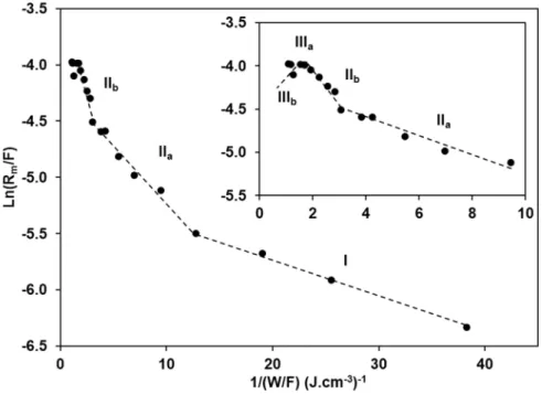
Figure 1 shows the graph ln(Rm/F) as a function of (W/F)-1 for plasma polymerization of maleic
anhydride onto SiO2, Si-OH and Si-CH3 substrates by varying the peak power (Pp) and the duty
cycle (DC) at a low pressure of 0.2 mbar. All operating conditions are given in Table S1 in Supporting Information. Taking into account the value of the experimental standard deviation on the deposition rate (± 6 nm.min-1), we recall here that the deposition rate was estimated by
measuring the variations in thickness as a function of the deposition time. The experimental values of ln(Rm/F) as a function of the inverse specific energy provide straight line segments
growth corresponding to five different linear segments can be clearly identified: domains I, IIa, IIb, IIIa and IIIb, respectively.
Figure 1. Arrhenius-type plot representation of macroscopic kinetics of maleic anhydride
plasma polymerization. A zoom of the higher input energy area is inserted.
In the regime I, an increase of the specific energy rises the deposition rate. From the slope of the linear fit, the apparent activation energy of maleic anhydride plasma polymerization was determined to be Ea = 35 ± 2 eV per molecule. Surprisingly, this value is much higher than the
value expected for oligomerization where the main polymerization mechanism is based on the opening of the carbon-carbon double bond (occurring at ~ 3 eV). Such level of energy in the plasma is enough to break all chemical bonds involved in the structure of the maleic anhydride molecule (C-C: ~ 3.6 eV; C-O: ~ 3.7 eV; C-H: ~ 4.2 eV and C=O: ~ 7.7 eV) but the absolute value of activation energy is probably overestimated since the calculations are based on the fact that 100% of the energy provided by the generator is effectively transmitted to the precursor gas. It is worth to notice here that the experimental configuration of the plasma reactor used in this work did not allow to work with energies lower than 0.03 J.cm-3 (corresponding to an
inverse specific energy of 38.3 J.cm-3), which could favor oligomerization. Experimentally, it
was not possible to initiate the plasma below this level of energy. It is also noteworthy that the input energy provided to the plasma chamber from the radiofrequency generator remains an average absolute energy supplied to the precursor but the spatial energy distribution inside the reactor can be heterogeneous.
When the input energy exceeds 35 ± 2 eV per molecule, a first transition in the plasma polymerization regime occurred with an increase in the growth kinetics (domain IIa in Figure 1). From the slope of the linear fit, a higher specific energy Ea of 139 ± 4 eV per molecule was
determined. Further increase in the energy input showed a second transition domain at 290 ± 7 eV per molecule (domain IIb). It can be noticed that the role of ions was much important in these two domains.
Significant slope changes have been observed in the two next domains. The deposition rate reaches a plateau (domain IIIa) and then drops (domain IIIb) at higher input energies (beyond 0.65 J.cm-3). This is due to the sputtering and etching processes, occurring simultaneously to
plasma polymerization.
The macroscopic kinetics approach for plasma polymerization of maleic anhydride allowed determining different regimes of polymer growth. These regimes are strongly related to the experimental configuration of the plasma reactor used in this study. In order to obtain a maximum content of anhydride groups in the plasma polymer thin film, the set of operating conditions Pp = 50 W, DC = 2 %, f = 816 Hz (corresponding to the input specific energy W/F
= 0.03 J.cm-3) was selected in order to minimize the role of the ions during the deposition
process.
In order to determine the impact of the surface properties of the substrate on the morphogenesis of maleic anhydride plasma polymer (MAPP), deposition of MAPP was carried out on different model silicon substrates SiO2, Si-OH and Si-CH3. This approach aimed at investigating
interactions of plasma species during MAPP growth with hydrophilic and hydrophobic surfaces. The deposition of MAPP was performed for exposure times varying from 2 seconds to 10 minutes in order to study the early stages of polymerization.
Chemical composition and hydrophilic/hydrophobic properties of MAPP thin films
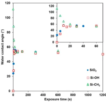
Figure 2 shows the water contact angle values measured on the three model substrates as a function of the exposure time (t) during plasma polymerization. The given value of the contact angle measured at t=0 corresponds to the value of the contact angle measured on the substrate without plasma exposure.
Figure 2. Equilibrium water contact angle values of the surface obtained after different
exposure times on SiO2, Si-OH and Si-CH3 substrates.Inset:zoom of the first 70s.
Similar trends have been observed for SiO2 and Si-OH substrates. The water contact angle
of Si-OH substrates. The water contact angle of 0° (t=0) for SiOH substrate compared to the water contact angle of 22° (t=0) for SiO2 is consistent with a more hydrophilic surface due to a
higher density of OH groups. In both cases, the water contact angle values reached a plateau after only 10 seconds of plasma exposure. The value of the plateau is the same (~ 55°-56°) which corresponds to a uniform coverage of the substrates with MAPP (this point will be confirmed later by surface analysis). Figure 2 shows also the variation of the water contact angle values of Si-CH3 substrates exposed to the plasma. The initial water contact angle of 111°
is characteristic of a hydrophobic surface as expected with the presence of methyl groups at the extreme surface of the Self-Assembled Monolayer (SAM). The water contact angle value decreased to reach a plateau at ~ 55° after 30 seconds of plasma exposure. Here again, the plateau value is consistent with a uniform coverage of the substrate with MAPP. The characteristic time to reach the plateau value is longer (30 s) on hydrophobic surface than on hydrophilic surfaces (10 s) but the plateau value is similar.
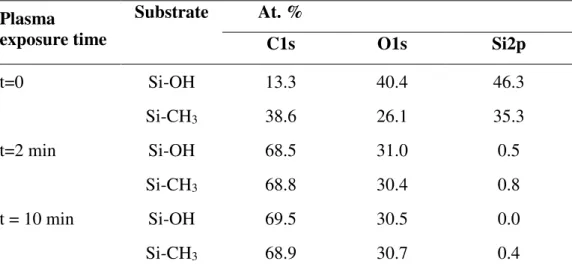
XPS analyses have been performed on hydrophilic substrate (Si-OH) and on hydrophobic substrate (Si-CH3) after 2 minutes and 10 minutes of plasma exposure (Figures 3, S2 and S3).
Atomic percentages of C1s, O1s, Si2p have been determined from the survey and high-resolution XPS scans (Table 1).
Table 1. Atomic percentages of C1s, O1s, Si2p before and after different plasma exposure times
on hydroxyl-rich silicon oxide layer (Si-OH) and alkyl-terminated SAM (Si-CH3)
Plasma exposure time Substrate At. % C1s O1s Si2p t=0 Si-OH 13.3 40.4 46.3 Si-CH3 38.6 26.1 35.3 t=2 min Si-OH 68.5 31.0 0.5 Si-CH3 68.8 30.4 0.8 t = 10 min Si-OH 69.5 30.5 0.0 Si-CH3 68.9 30.7 0.4
The chemical compositions of the substrates before plasma exposure are consistent with their expected chemistry. The presence of carbon on Si-OH substrate is due to contamination during substrate preparation and handling in air. The high proportion of carbon on SiCH3 confirms the
chemisorption of an undecyl trichlorosilane SAM at the surface of the substrate. Very interestingly, the atomic composition of the surfaces after plasma exposure are quasi-identical after 2 min and 10 min of plasma exposure and complete coverage of the underlying silicon substrate is confirmed by the absence of any Si2p signal. In addition, whatever the underlying substrate, the composition is similar, around 70 at. % of C and 30 at. % of O. This result indicates a similar chemical composition of MAPP films independently from the hydrophilic/hydrophobic properties of the substrate.
Besides, high resolution XPS scans performed on Si-OH and Si-CH3 substrates after 2 min and
10 min of plasma exposure indicate five types of carbon functionality in the C1s envelope (Figure 3a): aliphatic Csp3 carbon (C-C, CH
x 285.0 eV), carbon singly bonded to an anhydride
group or carbonyl group (-C-C=O- ~ 285.6 eV), carbon singly bonded to oxygen (-C-O ~ 286.5 eV), carbon doubly bonded to oxygen (O-C-O/-C=O ~ 287.9 eV), and anhydride group (O=C-O-C=O ~289.4 eV). The presence of anhydride groups is confirmed by the presence of two peaks in the high resolution spectra of the O1s (Figure 3b) corresponding to oxygen doubly bonded to carbon (-C=O) at 532.6 eV and oxygen singly bonded to carbon (O=C-O-C=O) at 533.9 eV. These results are in agreement with previously published data [9,18–20].
Figure 3. High resolution XPS spectra of a) C1s and b) O1s of the MAPP coating (here
obtained after 2 min of exposure on the Si-CH3 substrate).
The chemical composition of the MAPP thin films was confirmed by infrared spectroscopy. The following absorption features of cyclic anhydride groups were identified after plasma exposure (Figure S4): asymmetric and symmetric C=O stretching (1860 cm-1 and 1796 cm-1),
cyclic conjugated anhydride group stretching (1241 cm-1 - 1196 cm-1), C-O-C stretching
vibrations (1097 cm-1 - 1062 cm-1) and cyclic unconjugated anhydride group stretching (964
cm-1 – 906 cm-1). Others infrared bands are identified as carboxylic acid stretching (1730 cm-1)
coming from partial hydrolysis of anhydride groups. Low absorbance at 1630 cm-1 is
characteristic of some residual C=C bonds. The infrared band at 1227 cm-1 corresponds to the
Si-O vibration of the substrate. All FTIR spectra of maleic anhydride plasma polymer thin films were found to be in agreement with those previously published [9,18–20].
It is interesting to note that MAPP deposition occurs from the early stages of plasma exposure. Indeed, in all cases the characteristic band of C=O (symmetric) stretching at 1796 cm-1 was
already observed after 2s of plasma exposure (Figure S4). Besides, the absorbance of the characteristic groups of MAPP regularly increases with exposure time and similarly whatever
the substrate. For instance, the evolution of the intensity ratio of the C=O symmetric stretching band and the Si-O vibration band is depicted in Figure 4 for the three model substrates.
Figure 4.Evolution of theratio of the intensities of the FTIR absorption bands of C=O
symmetric stretching (1796 cm-1) I
(sym C=O) and Si–O vibration band (1227 cm-1) I(Si-O) with
plasma exposure time for the three model substrates.
Morphology of MAPP thin films
In order to investigate the morphology of MAPP deposited on the different model substrates, samples were characterized by XRR and AFM in the early stages of plasma exposure.
Electron density profiles obtained from the simulation of the experimental X-ray reflectivity curves (Figure S5) of the samples are presented in Figure 5. The parameters, including electron densities of the different raw materials used to fabricate the samples, are reported in Table S2.
Figure 5. Electron densities profiles of (a) the model substrates (references) and MAPP thin
films deposited after various exposure times on different substrates: (b) SiO2, (c) Si-OH, and
(d) Si-CH3.
First, the electron density profiles of the various substrates (Figure 5a) indicate the presence of a layer of around 10 Å having a density close but lower to the one of SiO2 (ρe=0.66 e.Å-3). This
can be due to the hydrolysis of Si-O-Si bond during their preservation at the laboratory atmosphere. For the Si-CH3 substrate, two zones can be observed: a zone located at the silicon
surface having a density close to the one of SiO2 and another located at the top with a density
(ρe=0.25 e.Å-3) lower than the theoretical density of grafted undecyl trichlorosilane (ρe=0.31
e.Å-3) which may attest of a surface coverage around 80%.
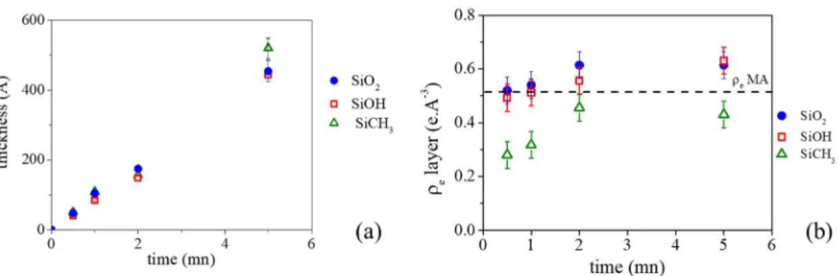
When looking at electron density profiles of MAPP thin films deposited on the different substrates (Figures 5.b, 5c and 5d), several conclusions can be made. First, whatever the samples, the thicknesses increase linearly until 5 min as illustrated by Figure 6a. Second, the electron densities of MAPP coatings are different from the density of MA: lower when the
coatings are deposited on Si-CH3 substrate and higher when they are deposited on SiO2 and
Si-OH samples (Figure 6b). Moreover, whatever the initial substrate, the electron density of MAPP thin films increases linearly with the exposure time until 2 min and reaches a plateau after.
Figure 6. Evolutions of the thickness (a) and electron density ρe (b) of the MAPP coatings as
the function of the exposure time on the different model substrates.
Third, as highlighted by the electron density profiles in Figure 6b, MAPP deposited on Si-CH3
substrate presents a zone having a low density between the SAM and the MAPP coating until 2 min of exposure time. This is not observed for MAPP deposited on hydrophilic substrates. Such phenomenon may attest a different association of plasma species growing from isolated nucleation points. That results in a less dense coating for Si-CH3 substrate as a consequence of
a low affinity of the species existing in the plasma with hydrophobic surface.
Figure 7 shows the AFM images of the three model substrates on which MAPP was deposited for 5, 10, 20 seconds and 1, 2, 5, 10 min. The MAPP thicknesses estimated by ellipsometry are reported on AFM images. In all cases, thickness values were in good agreement with those determined by XRR after only 1 min of plasma exposure. The AFM images acquired on SiO2
and Si-OH substrates reflect the formation of very homogeneous MAPP coatings. This confirms the rapid formation of a continuous MAPP film at Pp = 50 W, DC = 2 %, f = 816 Hz (pulsed
mode) on these two substrates. The formation of a homogeneous film is due to the strong affinity of plasma species for polar surfaces such as SiO2 and Si-OH as suggested by XRR
reflectivity.
On the other hand, AFM images acquired on Si-CH3 substrate reveal another MAPP film
formation mechanism. When the exposure time is short (as little as 5 seconds), small MAPP particles are formed and grow with exposure time. As the exposure time increases, the particles aggregate with each other. Indeed, they appear spherical until 1 min and take a rod-shape after 2 minutes. The growing of rod-shape particle leads to the formation of a rough textured surface.
Figure 7. Height AFM images (2 x 2 µm) of MAPP coatings obtained after different exposure
times on various substrates: (1st column) native silicon oxide surface (SiO
2); (2nd column)
hydroxyl-rich silicon oxide layer (Si-OH); (3rd column) alkyl-terminated monolayer (Si-CH 3).
3.3 Mechanism for MAPP structures formation
As presented previously, two original nanostructured morphologies of MAPP thin films having the same composition have been obtained depending on hydrophobic properties of the
substrate. While uniform films have been formed on hydrophilic substrates, for hydrophobic surface, a deposit made of aggregates is formed. This film growth is schemed on the Figure 8.
Figure 8. Schematic representation of MAAP film growth on hydrophobic and hydrophilic
surfaces.
At the beginning of the deposition process, plasma species collide with the substrate and may remained adsorbed on it. The probability that the species stays on the surface corresponds to their sticking coefficient. This value is related to the nature of the interactions between the plasma species and the substrate, which is governed by the chemistry of the plasma species but also of the chemical groups present at the extreme surface of the substrate. When a plasma of maleic anhydride is used, many polar species are formed and strongly interact with other polar groups, including those present on the substrate. Therefore, it is expected that many plasma species made of maleic anhydride are adsorbed on polar substrates, such as SiO2 or Si-OH at
the early stages of plasma exposure. This has been confirmed by water contact angle values that reach a plateau value (~ 55°-56°), corresponding to the typical value of MAPP thin films after only 10 seconds of plasma exposure. In addition, XRR results reveal the presence of a dense thin film from the very beginning of the deposition. On the contrary, the morphology of MAPP deposited on an apolar substrate is drastically different. AFM images show the presence of particles that progressively grow and aggregate. The film formation seems to be limited here by the presence of few nucleation points at the extreme surface of the hydrophobic SAM, due to the unfavorable interaction between the polar plasma species and the apolar groups present on the substrate. These nucleation points then grow thanks to the diffusion of new impinging plasma species on the surface, leading to the formation of particles. After 2 min of plasma exposure, the aggregation of several spherical particles results in the formation of rod-like particles (see also Figure S6). The rod-like structures continuously grow up as a function of time thanks to the diffusion of new plasma species adsorbed on the substrate and on the growing nanostructures, giving birth to elongated nanostructures as observed after more than 5 minutes of plasma exposition. Therefore, beyond the prevailing process conditions, such as gas pressure, surface temperature, plasma power conditions, this study highlights the remarkable effect of the physico-chemical nature of the substrate on the morphology of the MAPP thin films and the role of the sticking coefficient vs diffusion coefficient of the plasma species in the possible formation of nanostructured plasma polymers.
4
Conclusion
Morphogenesis of plasma polymer made of maleic anhydride has been investigated in this study. A macroscopic approach led to the determination of apparent activation energies related to the formation of specific plasma species according to the specific energy provided to the precursor gas and showed that mild operating conditions should be selected to retain a maximum of anhydride groups. Besides, a thorough study of MAPP film growth has been
performed on silicon substrates with different surface properties: two being hydrophilic and one being hydrophobic. The combination of different characterization techniques such as Fourier Transform Infrared Spectroscopy, X-ray Photoelectron Spectroscopy, Atomic Force Microscopy, ellipsometry, contact angle measurements and X-Ray Reflectivity has allowed getting better insight in the morphogenesis of MAPP film. Although very similar in their chemical composition MAPP coatings with drastically different morphologies were obtained according to the hydrophilic or hydrophobic nature of the surface of the substrate on which they were deposited. While uniform and dense MAPP coatings were observed from the very early stages of plasma polymerization on hydrophilic substrates as a consequence of the strong affinity of plasma species for the surface, an original nanostructured thin film was observed on the model substrate functionalized with an apolar SAM. Particles and subsequent rod-like nanostructures were formed, starting from isolated nucleation points on the hydrophobic substrate, leading to the unusual growth of much less dense MAPP films. This study has highlighted that not only operating conditions of plasma polymerization can generate spontaneously nanostructured plasma polymer coatings but that the nature of the interactions of plasma species with the substrate, related to their sticking and diffusion coefficients, highly directs the morphogenesis of plasma polymers.
Acknowledgements: The authors would like to thank Simon Gree, Ludovic Josien, Philippe Kunemann, Laure Michelin from the characterization platforms of IS2M for their technical support and discussions.
Keywords: growth kinetics; maleic anhydride; nanostructures; plasma polymerization; substrate chemistries
[1] K. Ostrikov, E.C. Neyts, M. Meyyappan, Plasma nanoscience: from nano-solids in plasmas to nano-plasmas in solids, Adv. Phys. 62 (2013) 113–224. https://doi.org/10.1080/00018732.2013.808047.
[2] H. Yasuda, Y. Matsuzawa, Economical Advantages of Low-Pressure Plasma
Polymerization Coating, Plasma Process. Polym. 2 (2005) 507–512.
https://doi.org/10.1002/ppap.200500002.
[3] S. Kulkarni, Plasma Assisted Polymer Synthesis and Processing, in: Non-Therm. Plasma Technol. Polym. Mater., Elsevier, 2019: pp. 67–93. https://doi.org/10.1016/B978-0-12-813152-7.00003-2.
[4] D. Losic, M.A. Cole, B. Dollmann, K. Vasilev, H.J. Griesser, Surface modification of nanoporous alumina membranes by plasma polymerization, Nanotechnology. 19 (2008) 245704. https://doi.org/10.1088/0957-4484/19/24/245704.
[5] S. Roualdes, I. Topala, H. Mahdjoub, V. Rouessac, P. Sistat, J. Durand, Sulfonated polystyrene-type plasma-polymerized membranes for miniature direct methanol fuel cells,
J. Power Sources. 158 (2006) 1270–1281.
https://doi.org/10.1016/j.jpowsour.2005.10.047.
[6] D. Bhattacharyya, K. Pillai, O.M.R. Chyan, L. Tang, R.B. Timmons, A New Class of Thin Film Hydrogels Produced by Plasma Polymerization, Chem. Mater. 19 (2007) 2222–2228. https://doi.org/10.1021/cm0630688.
[7] D. Debarnot, T. Mérian, F. Poncin-Epaillard, Film Chemistry Control and Growth Kinetics of Pulsed Plasma-Polymerized Aniline, Plasma Chem. Plasma Process. 31 (2011) 217–231. https://doi.org/10.1007/s11090-010-9271-2.
[8] A. Contreras-García, M.R. Wertheimer, Low-Pressure Plasma Polymerization of Acetylene–Ammonia Mixtures for Biomedical Applications, Plasma Chem. Plasma Process. 33 (2013) 147–163. https://doi.org/10.1007/s11090-012-9409-5.
[9] M.M. Brioude, M.-P. Laborie, A. Airoudj, H. Haidara, V. Roucoules, Controlling the Morphogenesis of Needle-Like and Multibranched Structures in Maleic Anhydride Plasma Polymer Thin Films: Maleic Anhydride Plasma Polymer Thin Films …, Plasma Process. Polym. 11 (2014) 943–951. https://doi.org/10.1002/ppap.201400057.
[10] M.M. Brioude, M.-P. Laborie, H. Haidara, V. Roucoules, Understanding the Morphogenesis of Nanostructures in Maleic Anhydride Plasma Polymer Films via Growth Kinetics and Chemical Force Titration: Understanding the Morphogenesis of
Nanostructures…, Plasma Process. Polym. 12 (2015) 1220–1230.
https://doi.org/10.1002/ppap.201400224.
[11] M.M. Brioude, V. Roucoules, H. Haidara, L. Vonna, M.-P. Laborie, Role of Cellulose Nanocrystals on the Microstructure of Maleic Anhydride Plasma Polymer Thin Films,
ACS Appl. Mater. Interfaces. 7 (2015) 14079–14088.
https://doi.org/10.1021/acsami.5b03302.
[12] G. Cicala, A. Milella, F. Palumbo, P. Rossini, P. Favia, R. d’Agostino, Nanostructure and Composition Control of Fluorocarbon Films from Modulated Tetrafluoroethylene Plasmas, Macromolecules. 35 (2002) 8920–8922. https://doi.org/10.1021/ma025536e. [13] R. Di Mundo, R. Gristina, E. Sardella, F. Intranuovo, M. Nardulli, A. Milella, F. Palumbo,
R. d’Agostino, P. Favia, Micro-/Nanoscale Structuring of Cell-Culture Substrates with
Fluorocarbon Plasmas, Plasma Process. Polym. 7 (2010) 212–223.
https://doi.org/10.1002/ppap.200900112.
[14] P. Favia, G. Cicala, A. Milella, F. Palumbo, P. Rossini, R. d’Agostino, Deposition of super-hydrophobic fluorocarbon coatings in modulated RF glow discharges, Surf. Coat. Technol. 169–170 (2003) 609–612. https://doi.org/10.1016/S0257-8972(03)00123-3. [15] A. Milella, F. Palumbo, P. Favia, G. Cicala, R. d’Agostino, Deposition mechanism of
nanostructured thin films from tetrafluoroethylene glow discharges, Pure Appl. Chem. 77 (2005) 399–414. https://doi.org/10.1351/pac200577020399.
[16] R. Förch, Z. Zhang, W. Knoll, Soft Plasma Treated Surfaces: Tailoring of Structure and Properties for Biomaterial Applications, Plasma Process. Polym. 2 (2005) 351–372. https://doi.org/10.1002/ppap.200400083.
[17] F. Siffer, A. Ponche, P. Fioux, J. Schultz, V. Roucoules, A chemometric investigation of the effect of the process parameters during maleic anhydride pulsed plasma
polymerization, Anal. Chim. Acta. 539 (2005) 289–299.
https://doi.org/10.1016/j.aca.2005.02.072.
[18] S. Schiller, J. Hu, A.T.A. Jenkins, R.B. Timmons, F.S. Sanchez-Estrada, W. Knoll, R. Förch, Chemical Structure and Properties of Plasma-Polymerized Maleic Anhydride Films, Chem. Mater. 14 (2002) 235–242. https://doi.org/10.1021/cm011139r.
[19] G. Mishra, S.L. McArthur, Plasma Polymerization of Maleic Anhydride: Just What Are
the Right Deposition Conditions?, Langmuir. 26 (2010) 9645–9658.
https://doi.org/10.1021/la100236c.
[20] M.E. Ryan, A.M. Hynes, J.P.S. Badyal, Pulsed Plasma Polymerization of Maleic Anhydride, Chem. Mater. 8 (1996) 37–42. https://doi.org/10.1021/cm9503691.
[21] V. Roucoules, W.C.E. Schofield, J.P.S. Badyal, Photo-rewritable molecular printing, J. Mater. Chem. 21 (2011) 16153. https://doi.org/10.1039/c1jm12758f.
[22] O. Soppera, A. Dirani, A. Ponche, V. Roucoules, Nanopatterning of plasma polymer reactive surfaces by DUV interferometry, Nanotechnology. 19 (2008) 395304. https://doi.org/10.1088/0957-4484/19/39/395304.
[23] J. Hu, C. Yin, H.-Q. Mao, K. Tamada, W. Knoll, Functionalization of Poly(ethylene terephthalate) Film by Pulsed Plasma Deposition of Maleic Anhydride, Adv. Funct. Mater. 13 (2003) 692–697. https://doi.org/10.1002/adfm.200304384.
[24] S.A. Evenson, C.A. Fail, J.P.S. Badyal, Controlled Monomolecular Functionalization and
Adhesion of Solid Surfaces, Chem. Mater. 12 (2000) 3038–3043.
https://doi.org/10.1021/cm000223o.
[25] V. Roucoules, F. Siffer, A. Ponche, U. Egurrola, M.-F. Vallat, Strengthening the Junction Between EPDM and Aluminium Substrate via Plasma Polymerisation, J. Adhes. 83 (2007) 875–895. https://doi.org/10.1080/00218460701699732.
[26] A. Airoudj, G. Schrodj, M.-F. Vallat, P. Fioux, V. Roucoules, Influence of plasma duty cycle during plasma polymerization in adhesive bonding, Int. J. Adhes. Adhes. 31 (2011) 498–506. https://doi.org/10.1016/j.ijadhadh.2011.05.003.
[27] M. Vauthier, L. Jierry, M.L. Martinez Mendez, Y.-M. Durst, J. Kelber, V. Roucoules, F. Bally-Le Gall, Interfacial Diels–Alder Reaction between Furan-Functionalized Polymer Coatings and Maleimide-Terminated Poly(ethylene glycol), J. Phys. Chem. C. 123 (2019) 4125–4132. https://doi.org/10.1021/acs.jpcc.8b10533.
[28] J. Bacharouche, F. Badique, A. Fahs, M.V. Spanedda, A. Geissler, J.-P. Malval, M.-F. Vallat, K. Anselme, G. Francius, B. Frisch, J. Hemmerlé, P. Schaaf, V. Roucoules, Biomimetic Cryptic Site Surfaces for Reversible Chemo- and Cyto-Mechanoresponsive Substrates, ACS Nano. 7 (2013) 3457–3465. https://doi.org/10.1021/nn400356p.
[29] R. Förch, A.N. Chifen, A. Bousquet, H.L. Khor, M. Jungblut, L.-Q. Chu, Z. Zhang, I. Osey-Mensah, E.-K. Sinner, W. Knoll, Recent and Expected Roles of Plasma-Polymerized Films for Biomedical Applications, Chem. Vap. Depos. 13 (2007) 280–294. https://doi.org/10.1002/cvde.200604035.
[30] A.T.A. Jenkins, J. Hu, Y.Z. Wang, S. Schiller, R. Foerch, W. Knoll, Pulsed Plasma Deposited Maleic Anhydride Thin Films as Supports for Lipid Bilayers, Langmuir. 16 (2000) 6381–6384. https://doi.org/10.1021/la991649o.
[31] S. Liu, M.M.L.M. Vareiro, S. Fraser, A.T.A. Jenkins, Control of Attachment of Bovine Serum Albumin to Pulse Plasma-Polymerized Maleic Anhydride by Variation of Pulse Conditions, Langmuir. 21 (2005) 8572–8575. https://doi.org/10.1021/la051449e.
[32] M. Macgregor, K. Vasilev, Perspective on Plasma Polymers for Applied Biomaterials Nanoengineering and the Recent Rise of Oxazolines, Materials. 12 (2019) 191. https://doi.org/10.3390/ma12010191.
[33] J. Friedrich, Mechanisms of Plasma Polymerization - Reviewed from a Chemical Point of
View, Plasma Process. Polym. 8 (2011) 783–802.
https://doi.org/10.1002/ppap.201100038.
[34] M. Asandulesa, I. Topala, V. Pohoata, Y.M. Legrand, M. Dobromir, M. Totolin, N. Dumitrascu, Chemically Polymerization Mechanism of Aromatic Compounds under Atmospheric Pressure Plasma Conditions, Plasma Process. Polym. 10 (2013) 469–480. https://doi.org/10.1002/ppap.201200068.
[35] L. Di, J. Zhang, X. Zhang, A review on the recent progress, challenges, and perspectives of atmospheric-pressure cold plasma for preparation of supported metal catalysts, Plasma Process. Polym. 15 (2018) 1700234. https://doi.org/10.1002/ppap.201700234.
[36] S. Ligot, D. Thiry, P.-A. Cormier, P. Raynaud, P. Dubois, R. Snyders, In situ IR Spectroscopy as a Tool to Better Understand the Growth Mechanisms of Plasma Polymers Thin Films: In situ IR Spectroscopy as a Tool to Better Understand the Growth
Mechanisms…, Plasma Process. Polym. 12 (2015) 1200–1207.
https://doi.org/10.1002/ppap.201400193.
[37] D. Hegemann, E. Körner, K. Albrecht, U. Schütz, S. Guimond, Growth Mechanism of Oxygen-Containing Functional Plasma Polymers, Plasma Process. Polym. 7 (2010) 889– 898. https://doi.org/10.1002/ppap.200900144.
[38] R. D’Agostino, ed., Advanced plasma technology, Wiley-VCH, Weinheim ; Chichester, 2008.
[39] A. Milella, R. Di Mundo, F. Palumbo, P. Favia, F. Fracassi, R. d’Agostino, Plasma Nanostructuring of Polymers: Different Routes to Superhydrophobicity, Plasma Process. Polym. 6 (2009) 460–466. https://doi.org/10.1002/ppap.200930011.
[40] G. Cicala, A. Milella, F. Palumbo, P. Favia, R. d’Agostino, Morphological and structural study of plasma deposited fluorocarbon films at different thicknesses, Diam. Relat. Mater. 12 (2003) 2020–2025. https://doi.org/10.1016/S0925-9635(03)00293-0.
[41] J. Böhmler, A. Ponche, K. Anselme, L. Ploux, Self-Assembled Molecular Platforms for Bacteria/Material Biointerface Studies: Importance to Control Functional Group
Accessibility, ACS Appl. Mater. Interfaces. 5 (2013) 10478–10488.
https://doi.org/10.1021/am401976g.
[42] R. Ober, Ober, Firefx4c_6: raymond.ober@college-de-france.fr, n.d.
[43] L.G. Parratt, Surface Studies of Solids by Total Reflection of X-Rays, Phys. Rev. 95 (1954) 359–369. https://doi.org/10.1103/PhysRev.95.359.
[44] D. Hegemann, H. Brunner, C. Oehr, Plasma Treatment of Polymers to Generate Stable,
Hydrophobic Surfaces, Plasmas Polym. 6 (2001) 221–235.
https://doi.org/10.1023/A:1014461932094.
[45] F. Bally-Le Gall, A. Mokhter, S. Lakard, S. Wolak, P. Kunemann, P. Fioux, A. Airoudj, S. El Yakhlifi, C. Magnenet, B. Lakard, V. Roucoules, Poly(allylamine) plasma polymer coatings for an efficient retention of Ni(II) ions by ultrafiltration membranes, Plasma Process. Polym. 16 (2019) 1800134. https://doi.org/10.1002/ppap.201800134.
[46] M. Veuillet, L. Ploux, A. Airoudj, Y. Gourbeyre, E. Gaudichet-Maurin, V. Roucoules, Macroscopic control of DMAHEMA and HEMA plasma polymerization to tune the surface mechanical properties of hydrogel-like coatings, Plasma Process. Polym. 14 (2017) 1600215. https://doi.org/10.1002/ppap.201600215.
[47] D. Hegemann, M.M. Hossain, E. Körner, D.J. Balazs, Macroscopic Description of Plasma
Polymerization, Plasma Process. Polym. 4 (2007) 229–238.
Graphical Abstract
The morphogenesis of maleic anhydride plasma polymer is investigated onto hydrophilic and hydrophobic surfaces. While homogeneous, smooth and dense polymer films are formed
on hydrophilic substrates, elongated nanostructures resulting in a less dense polymer film grows on the hydrophobic surface. These results are supported by a thorough characterization of the polymer thin films from the early stages of plasma exposure, including AFM and X-Ray Reflectivity.
Nghia H. Le1,2, Magali Bonne1,2, Aissam Airoudj1,2, Philippe Fioux1,2, Rémi Boubon3, Diane
Rebiscoul3, Florence Bally-Le Gall1,2, Bénédicte Lebeau1,2*, Vincent Roucoules1,2*