Automating Component-Based Testing From UML Models
by Bryan Che
Submitted to the Department of Electrical Engineering and Computer Science in Partial Fulfillment of the Requirements for the Degrees of
Bachelor of Science in Computer Science and Engineering
and Master of Engineering in Electrical Engineering and Computer Science at the Massachusetts Institute of Technology
May 15, 2000
Copyright 2000 Bryan Che All rights reserved.
The author hereby grants to M.I.T. permission to reproduce and distribute publicly paper and electronic copies of this thesis
and to grant others the right to do so.
Author__________________________________________________________________ Department of Electrical Engineering and Computer Science May 17, 1998 Certified by____________________________________________________________ Daniel Jackson Thesis Supervisor Accepted by_____________________________________________________________ Arthur C. Smith Chairman, Department Committee on Graduate Theses
Automating Component-Based Testing From UML
Models
By Bryan Che
Submitted to the
Department of Electrical Engineering and Computer Science
May 15, 2000
In Partial Fulfillment of the Requirements for the Degrees of Bachelor of Science in Computer Science and Engineering
And Master of Engineering in Electrical Engineering and Computer Science
Abstract
Software components such as EJB’s or COM objects may be tested in an automated fashion with the help of UML models. First, these objects should be modeled in UML, using certain extensions and modeling conventions. Then, an automated software-testing program can read the UML diagrams and generate testing scripts which drive the components appropriately. EJBTest is such a program which can read UML diagrams of EJB’s and generate the appropriate Java code for testing those EJB’s. The generated scripts can successfully test the EJB’s for functionality and also perform database verification.
Thesis Supervisor: Daniel Jackson Title: Associate Professor, MIT
1 Introduction
1.1 The problem with testing multi-tier, component-based programs
Within the past few years, many computer applications have been moving toward a multi-tier architecture and away from older, monolithic and client/server architectures. In this multi-tier world of software, software developers divide their programs into various tiers of functionality, grouping their designs around various hierarchies. Then, they write these various tiers and assemble them together to form a complete application. Usually, developers code one or more of these tiers (often the middle tiers) using software components.
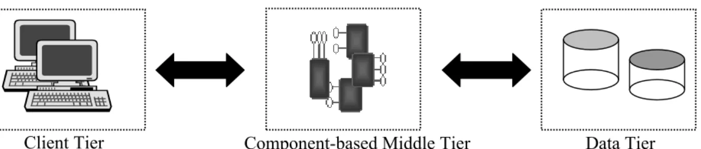
A typical example of multi-tier architecture is the three-tier, e-business model for computer applications (figure 1). The e-business model consists of three tiers, or layers: a user-interface tier, a middle tier, and a data tier. The user-interface tier is a thin layer (for example, a web browser) that interacts with the application’s user, and the data layer (often a database) stores the application’s data. The middle layer (e.g. an application server) is component-based and represents the application’s business logic—it processes information between the program’s users and the program’s data.
Writing multi-tier software with a component-based middle tier has several advantages over other architectures, including: it allows easy code reuse, it facilitates distributed computing, and it allows replacement of single or multiple components. These benefit have prompted many programmers to write multi-tier programs. However, despite these benefits, implementing multi-tier systems is quite challenging. One of the principal
Data Tier Component-based Middle Tier
Client Tier
reasons for this difficulty is that there are no standard methods or tools for testing component-based middle tiers.
There are many software tools on the market that automate the testing of programs. However, these programs generally drive the GUI of the application they are testing, looking for undesired behaviors and bugs. These GUI-based testing programs do not work well when testing multi-tier, component-based programs. This is because they cannot directly test the heart of multi-tier programs: since multi-tier programs separate their user interface from their logical components, software that only tests GUI’s cannot directly test these logical components for bugs.
Other reasons that GUI testing tools may be inappropriate for testing multi-tier programs include: there might be no GUI at all, and there may be too many flavors of GUI clients (i.e. multiple browsers on multiple platforms).
As an example of the limitations of GUI-testing software, consider a program—call it MyMultiTierProgram—that allows its user to change his password. A GUI-based test of this change-password procedure might enter a username and a password into MyMultiTierProgram’s password dialog box. If an error occurred during the password change, the GUI-driving testing program would be able to report that it had found a bug. But, the testing program would not be able to say where the bug was located—it would not know if MyMultiTier’s login was buggy in its user lookup component, its password-verification component, its component updating the user’s password in a database, or some other component. All these components, which contain the functionality of MyMultiTierProgram, are located in a middle tier and invisible through the GUI.
A much better way to test MyMultiTierProgram would be to bypass MyMultiTierProgram’s GUI altogether and test its middle-tier components directly. Then, it would be easy to know in which component—and even where in that component—the password-change bug was occurring. One would only have to see which component did not function properly. Furthermore, since many components
interact directly with a database, testing components directly makes it possible to automate testing for bugs in database manipulation: one could call a certain component’s method and then examine the database to make sure that method call updated the database correctly. There are no current tools, however, that automate testing in this manner.
1.2 Modeling software with UML
Many programmers now begin their software development efforts by modeling their new project with the Unified Modeling Language (UML). UML is a graphical language that allows software architects to create a blueprint for object-oriented programs. It provides semantic rules for:
•= Names What you can call things, relationships, and diagrams •= Scope The context that gives specific meaning to a name •= Visibility How those names can be seen and used by others
•= Integrity How things properly and consistently relate to one another •= Execution What it means to run or simulate a dynamic model1
By modeling their programs with UML, developers can describe how these programs should function. So, if a developer modeled a component-based program with UML, he could design things such as what components his program would have, how the components related to each other, what the components could do, and how the components were grouped or tiered. He could describe the program’s GUI, it logic, its data, and how these three tiers operated and interacted with each other. Once he had described his program in this way using UML, he only had to translate his design into code (and augment his code to fill in for things his model did not describe precisely) in order to produce his application.
1.3 Thesis Goals
My main purpose in this thesis project was to find a way to automate component-testing by leveraging the expressive power of UML. I wanted to help people model their software components with UML in such a way that would facilitate automated testing of those components. To do this, I formulated three thesis goals:
1.3.1 Extending UML
Early on in my research, I found that UML diagrams were not detailed or robust enough to describe all the information necessary for inferring precisely how components interact and operate. Therefore, as an initial goal for my thesis, I needed to find a way to augment UML which would make it capable of modeling component-based applications in a sufficient manner.
1.3.2 Modeling and testing methodology
My next thesis goal was to investigate testing and modeling methodologies for based applications. I wanted to explore how to create models of component-based software so that the models would be rich enough to generate test scripts. I also wanted to examine and determine how to go about testing component-based applications.
1.3.3 Software tool
My final goal for this thesis was to write a software tool that would implement my testing methodologies and automate generating test scripts for a component-based application from a UML model of that application. My program would take in a UML description of a component-based application. Then, it would analyze this UML model, ask the user to select a component in that model which he would like to test, and generate scripts that drive the selected component as it was modeled to operate and interact in the application. With these scripts, the application’s tester could test his program’s functionality by observing how various components performed when executing an action.
In addition to providing this basic functional testing capability, my software tool would focus on automating database verification. Since many middle-ware components manipulate a database, my tool would be able to verify that these components correctly updated database values.
Going back to the MyMultiTierProgram example, a tester would not have to test MyMultiTierProgram’s change-password procedure through its GUI by entering data into its password dialog. Instead, he could execute the scripts my tool would generate and observe how the various components that implement login functioned and interacted. He could observe in which components and where in those components errors occurred. Furthermore, he could use my tool to verify that the users table within his database now had the correct, updated password from the password change.
Using UML models as an entry point for my testing program is useful for a couple reasons. First, the program needs to know through some means how to test the components of the application it’s analyzing. UML is a good and standard way to accomplish this. Second, many programmers already use UML in designing their software. By using a tool that reads UML models, these programmers can re-use work that they have already done when testing their applications.
1.4 What it means to test
For the purposes of this thesis, I test components in two ways:
1.4.1 Verification of results
My thesis project tests a component’s performance against “correct” answers. That is, the tool automatically drives a component and compares the component’s results with known, proper results to verify that they are the same. These proper results may come from previous runs of the tool upon older versions of the component, or they may come from some other source. One of the primary ways my thesis project tests correctness is by doing database verification. That is, my project determines if a component is correctly updating a database’s values if that component should manipulate the database.
This test, in addition to helping people do database verification, is useful for people who want to update a component and swap it with an older, existing component in a live system. These people can verify that their new component will not break anything in their live system.
1.4.2 Understanding what to test and in what sequence
My thesis project tests how a component performs as part of a system; it tests if a component properly performs a sequence of events during a larger, overall action. For example, say MyMultiTierProgram implements its login action within a component-based middle tier. Let one of the components that is part of this login be the user component. My project can test that the user component performs certain sequential events properly during the login action.
This test is useful for people who want to accurately test components in a distributed environment because it allows them to single out components for testing and know how to test that component as if it were being used as part of some action.
2 Background
2.1 Component Architectures
There are currently two principle component architectures which people use to write multi-tiered systems: Microsoft’s Distributed Component Object Model (DCOM) and Sun Microsystem’s Enterprise JavaBeans (EJB). DCOM and EJB are similar in many regards and have basically the same functionality. However, DCOM runs principally on Microsoft Windows, whereas EJB can theoretically run on any platform.
DCOM objects are components that must be implemented within a host server. They export interfaces, each of which contains various methods (functions). Clients can obtain pointers to these interfaces and then call the methods within them.2
Enterprise JavaBeans reside within a host container, which resides within a host server. The bean container export methods which EJB clients can call; clients never directly access an EJB. Instead, EJB clients call container-generated methods which invoke the beans’ methods.3 There are two types of EJB containers: session and entity. Session containers hold session beans, which are non-transactional, non-persistent beans. Entity containers, on the other hand, hold entity beans, which are transactional and persistent. In addition to being persistent, entity beans directly represent data within a database.
Figure 3 Enterprise JavaBean
For this thesis, I chose to focus upon EJB. Since both DCOM and EJB are similar component technologies, choosing one over the other should not affect my thesis results.
Server Interface Interface Pointer to Interface Pointer to Interface Interface DCOM Object Client Figure 2 DCOM
2.2 Rational Rose™
Rational Rose™ is a UML modeling program created by Rational Software Corporation. Other UML modeling programs include Elixir Technologies’ Elixir Case, Object Domain Systems’ Object Domain, and Softera’s SoftModeler. Rational Rose can create UML models from scratch. In addition, it can reverse-engineer UML models from existing applications and generate code frameworks from UML models. I used Rose to generate the UML models for my testing tool.
The testing and design methodologies in this thesis should work with any UML-compliant tool. But, Rose offers the advantage of exposing a well-documented COM-interface that allows users to manipulate Rose and Rose UML models through other programs. The software tool that I wrote to implement my modeling and testing methodologies took advantage of this COM interface to parse Rose UML diagrams.
2.3 UML Interaction Diagrams
One of the constructs of the UML is the interaction diagram. Interaction diagrams describe the dynamic aspects of a system: they detail various scenarios that can occur within the system. The diagrams do this by representing the various participants within an interaction as objects or class instances. These participants relate to one another by sending message instances. For example, an interaction diagram might model a scenario where a person drives a car. In the interaction diagram, the object person would send the message instance to the object car: drive.
Depending on the circumstance, a modeler may choose between two types of interaction diagrams: sequence diagrams and collaboration diagrams. Sequence diagrams emphasize the time ordering of messages between objects, and collaboration diagrams focus on the objects that interact and the relationships between them. Collaboration diagrams tend to share information with class diagrams, which describe the details of the classes that specify the objects found in interaction diagrams. Sequence diagrams and collaboration
diagrams are semantically equivalent; modelers may use them interchangeably with no loss of information.
Figure 4 A Sample Sequence Diagram Created in Rational Rose
My program generates code that implements the actions in interaction diagrams of EJB objects.
2.4 UML Class Diagrams
UML class diagrams describe all the participants (classes) in a system and how they are related to each other. Unlike interaction diagrams, class diagrams describe how a system is structured rather than how it behaves.4
I used class diagrams to describe the structure of EJB systems.
Figure 5 A Sample Class Diagram Created in Rational Rose
2.5 Java
Java is a safe, object-oriented language that is platform independent and supports EJB. My testing tool generates Java code for its scripts.
2.6 Prior Work
My thesis extends some prior work that a couple people and I had already performed at Rational Software. We had already done some basic test-script generation from UML models of COM objects. However, this thesis project is unique because it:
•= Concentrates on automating the testing of EJB objects
•= Identifies problems with modeling specific EJB technologies in UML and Rose •= Automates database verification
3 Project
Description
My thesis project consisted of three primary parts corresponding to my three thesis goals:
3.1 Extending UML
UML, in its current form, is not rich enough to describe interactions in a detailed way. One of the areas in which it is most lacking is the area of dynamic data correlation. UML interaction diagrams do not have any standard means of communicating basic things such as:
•= This function takes as an argument a value which another function returned •= These two objects are the same
•= Assign this object to be that object
Knowing how to dynamically correlate data is necessary for communicating meaningfully how to test a component. Therefore, I am using an extension to UML for this thesis project in order to support dynamic data correlation.
In his thesis work, Correlation of Dynamic Data in the UML Interaction Diagram5, Jonathan Lie describes extensions to UML interaction diagrams which allow them to dynamically correlate data. I am using these extensions for my thesis project, with one exception: due to limitations in Rose, I do not support initializing variables in UML use case diagrams—only in interaction diagrams.
3.2 Devising a Modeling and Testing Methodology
3.2.1 Modeling EJB’s
There has already been a draft of an EJB/UML mapping submitted to the Java community: UML Profile For EJB6. I used this document as my basis for modeling EJB’s. However, this UML profile did not address how to model certain EJB aspects
which I required for my thesis project. Therefore, I devised additional EJB modeling conventions:
3.2.1.1 <<RelationalTable>> Class
Entity beans directly represent data in a database; they typically map to a single row within a database table. A UML class diagram which shows a class stereotyped as <<EJBEntity>> must also have a class stereotyped as <<RelationalTable>> (a stereotype is a UML mechanism for introducing new modeling elements. So, <<RelationalTable>>.introducing an <<EJBEntity>> stereotype, for example, means introducing an EJB Entity bean as a valid modeling element within a UML diagram). This <<RelationalTable>> class represents the database table to which the <<EJBEntity>> class maps.
A <<RelationalTable>> class tied to an <<EJBEntity>> class must support the following tagged values:
Tag Value
DataSourceURL The data source URL identifying this database table
JDBC The JDBC driver to use when connecting to this database table
User The username to use when logging into this table Password The password to use when logging into this table
Table 1 <<RelationalTable>> Tags
These tagged values provide sufficient information about how to programmatically connect to a relational table and manipulate it using JDBC.
As in normal <<RelationalTable>> classes, attributes represent table columns.
3.2.1.2 <<EJBAssociation>> Link
A UML class diagram which depicts EJB classes must have a link stereotyped as <<EJBAssociation>> between classes with the following stereotypes:
•= <<EJBRemoteInterface>> and <<EJBEntity>> •= <<EJBRemoteInterface>> and <<EJBSession>> •= <<EJBPrimaryKey>> and <<EJBHomeInterface>> •= <<EJBPrimaryKey>> and <<EJBEntity>>
•= <<EJBPrimaryKey>> and <<EJBSession>> •= <<EJBPrimaryKey>> and <<RelationalTable>> •= <<EJBEntity>> and <<RelationalTable>>
This <<EJBAssociation>> link identifies which classes relate to the single EJB represented by the <<EJBEntity>> or <<EJBSession>> class. The <<EJBAssociation>> link is necessary in the event that the class diagram holds more than one EJB. If this were the case, then it would not be clear which group of EJB interfaces comprised a single EJB. For example, in a system with two EJB’s, there would be two Home Interfaces and multiple Remote Interfaces. Without <<EJBAssociation>> links linking specific remote interfaces to specific home interfaces, one would not be able to distinguish readily which remote interfaces grouped with which home interface.
3.2.1.3 EJBCorrespondingDBColumn Tag
This tag applies to <<EJBEntity>> and <<EJBPrimaryKey>> class attributes:
Tag Value
EJBCorrespondingDBColumn The name of the database column to which this attribute maps in the EJB’s associated relational table
Table 2 EJBCorrespondingDBColumn Tag
3.2.1.4 Modifies Tag
This tag applies to <<EJBEntity>>, <<EJBSession>>, and <<EJBPrimaryKey>> operations:
Tag Value
Modifies A semi-colon delimited list of the attributes which this operation modifies
Table 3 Modifies Tag
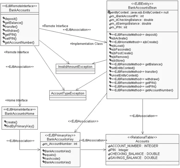
The following figure illustrates a UML class diagram, modeled using the UML profile and my own additions:
Figure 6 A Class Diagram with an EJB
In this diagram, there is an EJB for a bank account. It is implemented through the <<EJBEntity>> class, BankAccountsBean. This class is associated with the database table, Accounts—as the <<EJBAssociation>> link between these two classes indicates. The Primary Key for this EJB is BankAccountsKey, also indicated by the <<EJBAssociation>> link between the <<EJBPrimaryKey>> and the <<EJBEntity>> classes. The home interface and remote interface for this bean are, respectively,
BankAccountsHome and BankAccounts. They are both linked together with <<EJBAssociation>> links and tied to the primary key.
Note that all the classes and interfaces which comprise the bank account EJB are glued together with <<EJBAssociation>> links. If there were multiple EJB’s within this class diagram, it might not be clear exactly which classes belonged to which EJB. For example, it might be difficult to discern which <<EJBPrimaryKey>> classes corresponded to which <<EJBEntityClass>> without an explicit <<EJBAssociation>> link.
3.2.1.5 EJB’s in Interaction Diagrams
Interaction diagrams describe how objects in a system behave with respect to each other. Thus, developers who want to explain how to use an EJB can do so with an interaction diagram. One of the things he must decide, though, is what level of detail to put into the interaction diagram. In the case of modeling EJB’s, beans require initialization. This initialization is a standard process for all Enterprise Java Beans, so it does not add much value to model the entire initialization process. On the other hand, someone looking at an interaction diagram with an EJB in it should understand how to create that EJB precisely the way that the diagram intends. Thus, the interaction diagram should contain just enough data for modeling EJB initialization—but not too much, lest the diagram become cluttered with useless details.
For this thesis project, I have defined what information a modeler must put into an interaction diagram to initialize an EJB. I have chosen to model only the critical steps for defining the creation of the EJB. All other EJB initialization steps are essentially the same and do not communicate new information.
Once a modeler has initialized his EJB, he can treat his EJB object as no different from any other type of object—allowing him to design his diagram as he would any interaction
diagram. Interaction diagrams modeling EJB usage must be specified at the instance level.
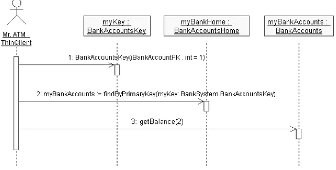
3.2.1.5.1 Initializing Entity Beans
To initialize an entity bean, the interaction diagram must contain the following two messages in order:
1. A message to an instance of the <<EJBPrimaryKey>> class initializing that object instance.
Let myKey be the name of an <<EJBPrimaryKey>> object, whose class is KeyClass. Then, this message must have the form:
myKey := KeyClass([arguments])
2. A message to the EJB’s home interface (<<EJBHomeInterface>>) initializing the remote interface.
Let myRemoteInterface be the name of the EJB’s remote interface and myHomeInterface be the name of the EJB’s home interface. Furthermore, let myKey be the primary key which was initialized in the previous step. Then, the message must have the form:
MyRemoteInterface := findByPrimaryKey(myKey)
After these two steps, the EJB is initialized, and the modeler may send messages to the EJB remote interface.
Figure 7 A Sequence Diagram Initializing and Using an Entity Bean
3.2.1.5.2 Initializing Session Beans
Initializing Session beans in an interaction diagram only requires one message to the session bean’s home interface. Let myRemoteInterface be the name of the EJB’s remote interface. Then, this message to the home interface must have the form:
MyRemoteInterface := create([arguments]) After this step, the session bean is initialized.
Figure 8 A Sequence Diagram Initializing and using a Session Bean
3.2.2 Testing EJB’s
3.2.2.1 Functional Testing
Testing EJB’s requires knowing what the EJB’s are, what to do with them, and how they should behave. If a tester wishes to test a bean and has a UML model of that bean, created according to my modeling conventions, then he can extract all the information from the model which he needs for verification. The tester can do this by performing the following steps:
1. Identify within the class diagram the EJB (and its related classes) to test.
To do this, the tester must select a class stereotyped as <<EJBEntity>> (an entity bean) or <<EJBSession>> (a session bean). Then, he must identify the bean’s corresponding remote interface and home interface. If the EJB is an entity bean, he must also find its primary key class. All of these classes should be linked, directly or indirectly, with <<EJBAssociation>> links. Thus, the tester must simply just select a bean and find its related classes by following links.
2. Select an interaction diagram which depicts the EJB to test. 3. Initialize and drive the EJB as the interaction diagram describes.
For example, in figure 6, the tester could choose to test BankAccountsBean, an <<EJBEntityBean>> component. Then, he could find the remote interface, BankAccounts, by following an <<EJBAssociation>> link. From BankAccounts, he could find the home interface, BankAccountsHome. He could then find the Primary Key class, BankAccountsKey, by following an <<EJBAssoication>> link from the home interface.
Once he had identified these classes, the tester could select to use the interaction diagram shown in figure 7 to test BankAccountsBean. This diagram says to create a BankAccountsKey named myKey. Next, it says to assign the remote interface object, myBankAccounts, to the value returned by calling the home interface’s findByPrimaryKey() method. Finally, it states to call myBankAccounts’ method, getBalance(). This sequence of steps corresponds to the java code:
BankAccountsKey myKey = null; myKey = new BankAccountsKey(1); BankAccounts myBankAccounts = null; try
{
myBankAccounts = myBankHome.findByPrimaryKey(myKey); }
catch (Exception ce) { return; } try { myBankAccounts.getBalance(2); } catch (Exception e) { return; }
Following this simple procedure enables the tester to test a component he might not be able to test without a UML model explaining what to do. Because the component probably only exposes an interface and requires special initialization, the tester would not
know how to create the component if he only had the component and its API. Furthermore, he would not know how the component was supposed to perform or what it was intended to do. The UML model explains this, allowing him to test the component.
3.2.2.2 Database Verification
In addition to helping a tester know how to initialize and test an Enterprise Java Bean’s functionality, a UML model can help a tester perform database verification on an entity bean. The tester can use the UML model to perform database verification by doing the following:
1. Find the entity bean’s corresponding relational table.
The tester can do this by following an <<EJBAssociation>> link from the bean’s primary key class.
2. Find the <<EJBRemote>> methods in the bean’s implementation class (<<EJBEntity>> class) corresponding to the methods being called from the bean’s remote interface.
If the UML interaction diagram depicts calling a method, foo(), from the EJB’s remote interface, then the tester must find the corresponding method named foo() and streotyped <<EJBRemoteMethod>> in the <<EJBEntity>> class.
3. Look at the modifies tag for each method in the bean’s implementation class and note what, if any, bean properties these methods modify.
4. For each property which a method modifies, find that property’s EJBCorrespondingDBColumn tag and note to which table column this property corresponds.
5. For each database column noted in the preceding step, perform a SQL query to verify its value in the database.
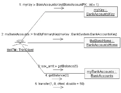
Figure 9 A Collaboration Diagram of a Transfer
The person testing myBankAccounts in this diagram might want to verify that the account balances in myBankAccounts’ corresponding database table were valid after calling myBankAccounts’ transfer() method. He would know to do this and know how to do this by first looking in myBankAccounts’ class diagram (figure 6) and finding the <<RelationalTable>>, Accounts. Then, as he examined the messages sent to myBankAccounts, he would find that the method, transfer(), modifies two properties: m_dCheckingBalance and m_dSavingsBalance. He would then find that these properties correspond to the database columns, CHECKING_BALANCE and SAVINGS_BALANCE, respectively. He would then perform SQL queries upon these two columns to verify their values.
Following these steps allows a software tester to understand how an EJB modifies database values and perform database verification. Without a UML model, the tester would not have enough information from just the EJB do know how to test that it was functioning properly when updating database values.
3.3 Creating a Software Tool
3.3.1 Software Architecture
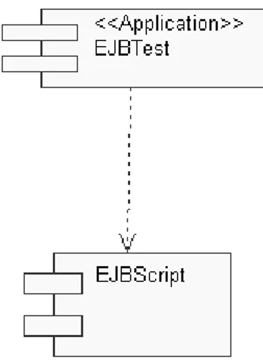
I created a software application, EJBTest, to apply my EJB modeling and testing methodologies. EJBTest is just a simple shell, though—I architected my application so that all of its real functionality resides within a Windows dll, EJBScript. Putting the functionality into a dll enables other applications in addition to EJBTest to validate EJB’s.
Figure 10 Component Diagram of EJBTest
EJBScript performs by gathering information from its user about what EJB to test and then generating Java test scripts to test that EJB. To do this, it first prompts its user to select a Rational Rose file containing a UML model of an EJB system. Then, it asks the user to identify the class diagram in that model which describes the EJB system. Then, it asks the user to select an interaction diagram stating how to drive the EJB. Finally, it generates and returns Java code implementing the interaction diagram’s depiction.
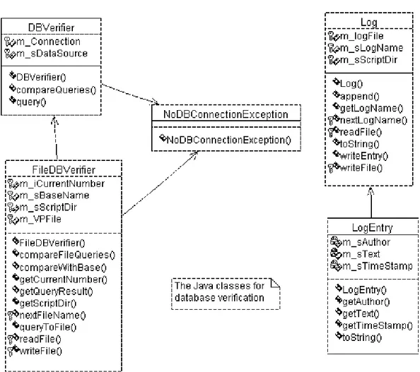
In addition to creating EJBTest and EJBScript, I wrote a Java package, com.rational.test.ejb, to facilitate logging and database verification. The Java code which EJBScript generates uses this package to allow the tester to log errors and results and examine his database.
Figure 11 Class Diagram of com.rational.test.ejb Java Package
3.3.2 Sample Walk-Through
3.3.2.1 Step 1: Start Application
EJBTest launches as a simple dialog box which starts the script-generation process. All a user has to do is press the dialog’s button.
Figure 12 EJBTest Start
3.3.2.2 Step 2: Select Project Directory
The first thing EJBTest does is prompt its user for a project directory. The program will store the script and its associated log and verification point files within this directory.
Figure 13 Select Project Directory, EJBTestScripts
3.3.2.3 Step 3: Name Script
Next, EJBTest asks its user to name the script it will be generating. EJBTest will save the script with this name, and it will also create a new directory under the project directory with this script’s name.
In this script directory, EJBTest will also create sub-directories named log and vps. It will store the generated script’s log files in log and the script’s verification-points files in vps.
Figure 15 The Script Directory, TestTransferScript, under the Project Directory, EJBTestScripts
3.3.2.4 Step 4: Select Rose Model
EJBTest will then prompt the user to select a Rational Rose model which contains the UML diagrams of the EJB to be tested. If the user happens to run EJBTest from within Rose, however, Rose may already have a model open. In that case, EJBTest will use the currently-open model and skip this step.
Figure 16 Select Rose Model, BankSystemFinal.mdl
3.3.2.5 Step 5: Select Class Diagram
Once EJBTest has opened the selected Rose model, it will scan the model for class diagrams. Then, it will present these class diagrams to the user and ask him which one contains the EJB system he would like to test.
Figure 17 Select Class Diagram, bank.accounts Classes
3.3.2.6 Step 6: Select Interaction Diagram
After selecting a class diagram, the user must select an interaction diagram which models how to use the EJB he wants to test. Note that Rational Rose calls interaction diagrams scenario diagrams; hence, EJBTest prompts for scenario diagrams rather than interaction diagrams.
3.3.2.7 Step 7: Create a Log
The script that EJBTest generates supports logging through the class Log in the com.rational.test.ejb package. Every time the user runs the generated script, a new log file is created, and the results of that run are stored in that log file. So, if a user has run the script seven times, then there will be seven log files—one for each run. Each of these log files will have the same base name with a number appended to it. This step prompts the user for the base name of the log.
Figure 19 Naming the log TransferLog
3.3.2.8 Step 8: Select an EJB
The user has already selected a class diagram and interaction diagram. Now, EJBTest displays a list of all EJB’s in the selected interaction diagram and asks the user which one he would like to test.
Figure 20 Selecting the EJB, myBankAccounts
3.3.2.9 Naming the VP
If the user is testing an entity bean, then EJBTest will generate database verification code for the bean as part of the test script. Each run of the script will save the results of its database verifications into a verification-point file. So, if the user runs the generated script eight times, then there will be eight verification-point files, with each one containing the database results from its corresponding run. Each of these verification-point files will have the same base name with a number appended to it. This step prompts the user for the base name of the verification-file.
3.3.2.10 Generating the Script
At this point, EJBTest has enough information to generate its script. It places the new test script in the Script directory and exits.
Figure 22 Finished Generating Script
The user may now take the newly generated Java script, compute its classpath, compile it, and execute it. The sample script generated from this application walk-through is located in Appendix A. A sample verification-point file created by running the script is found in Appendix B. A sample log file created from running the script is located in Appendix C.
To summarize the script and its results, EJBTest generated a Java script which tests the entity bean, myBankAccounts. It performs a series of balance checks and then an accounts transfer upon the bean. EJBTest recognizes that the bean’s transfer() method modifies the CHECKING_BALANCE and SAVINGS_BALANCE columns in the associated database table. So, the generated script queries the database for these values and saves them into a verification-point file found in Appendix B. The generated script also saves a log, like the one in Appendix C.
3.3.3 Verifying Results
The first time the user runs the generated script, the results are stored in base log and verification-point files. Every subsequent run of the script will store its results in a new log and verification-point file. Furthermore, it will also compare its database-verification results with those of the base run. If the new run results in the same values as the base run, then the log notes that nothing has changed in the EJB. If the results are different, however, then the EJB has functionally changed since the last time the user tested it. Therefore, there is a potential error in the EJB, and the log notes that fact. Appendix C shows a log file pointing out an error.
These log and verification-point files help the user automate testing—all the user must do is run the script. If the EJB is broken, he will see it from the files. If the results are the same, he will also note this from the files. Thus, if the tester receives a new version of a bean and wants to verify that it still performs old methods properly, he can quickly do so with his generated script.
4 Thesis
Results
My software tool, EJBTest, serves to validate my UML extensions as well as my EJB modeling and testing methodologies; if EJBTest is functional and valuable, then my extensions and methodologies are adequate for automating the testing of EJB’s.
I tested EJBTest on a variety of sample EJB’s, modeled with my extensions and conventions. I tested both session beans and entity beans, and in all cases, EJBTest successfully generated scripts which drove those beans. Furthermore, it successfully checked database values which entity beans modified.
Most of these EJB’s I tested were small beans with only a few functions. The one relatively large EJB I wrote was the bank account EJB which I presented earlier in section three. The relative sizes of these beans does not really matter, though. My methodology only tests EJB’s one scenario at a time—it does not generate scripts for the entire bean at once. Furthermore, a bean can have a relatively large number of interaction scenarios compared to its number of functions.
For example, for the bank account bean, a person could login and get his balance. Or, he could login and make a deposit and get his balance. Or, he could login, make a deposit, make a transfer, and then get his balance. Or, he could login, make a transfer, and then make a withdrawal, and then get his balance, and so on. Clearly, there are a number of various interactions that could occur with even a small set of functions. A real tester probably would not be interested in testing all of these various scenarios. But, the fact
that my methodology and software is able to generate tests for all these scenarios validates my work.
Although I found that my modeling and testing methodologies perform well in principle, there are some limitations to automating component testing with UML diagrams. First of all, UML does not have a single, standard way of modeling looping and branching constructs within interaction diagrams. There are various ways in which a person might model looping or branching, and they allow using free text to describe what is happening in a diagram. Consequently, it can be difficult for a an automated-testing program to decipher a diagram that involves iteration or if statements.
One solution to this problem would be to define a standard way to model looping and branching within diagrams containing EJB’s. However, since Rational Rose does not support modeling looping or branching at all within interaction diagrams, I did not explore doing this. I do not see any reason why this would not be possible, though.
Still, if a person wanted to test an EJB that involved branching, he could do so in a limited fashion with my EJBTest software. To test branching logic, he could create an interaction diagram for each possible path that a program might take. This is clearly not ideal, but it is perhaps better than nothing.
Another potential limitation to my testing methodology is that the person designing (and maybe even implementing) the EJB is also the person designing the UML diagrams for testing the EJB. This person will obviously have pre-conceived notions about how to use the EJB, and he might not be thorough in designing tests for his component due to his lack of objectivity. However, a third party might not be able to test that component at all without some explanation from the component’s designer since the component may not expose a clear interface. Therefore, this seems to be more a limitation of component-testing than my methodology for automating component component-testing.
One other consideration for using UML to describe how to test a component is that as the component becomes more complicated in its interactions, the UML diagrams describing those interactions become more complicated as well. If the component grew too complex, the proper UML diagram for that component might be too unwieldy for someone to model properly. But, UML is a simple, graphical language. If a component did grow to the point where a UML diagram of that component was too difficult to understand or create, then the component itself is probably too complex. After all, if a person cannot clearly and thoroughly explain what a component does, how can he possibly hope to test it completely—automated or otherwise?
All of these issues do not seem too problematic compared to the advantages of automating component-testing with UML. UML is a rich, yet simple, and widely-used language. With the proper extensions and conventions, people can use it to describe how to test a component and automate testing of that component. And, because most UML modelers model during the design phase of a project, they will not have to do significant extra work to facilitate automated component testing—they can simply re-use their existing models.
Based upon these results, my UML work and my methodologies are for sufficient for automating component-testing. If someone wishes to model and test an EJB, he may simply follow my techniques. Then, he could use EJBTest to automate testing of that EJB. A tester wouldn’t need someone to explain to him how to initialize an EJB, what to do with that bean, or if that bean manipulated a database. All this information is captured within the UML model, so the tester just needs to input the UML model into a program which automates testing for him. My EJB modeling and testing practices enable testers to validate components—which they might not be able to otherwise test—in a methodical manner.
5 Conclusion
In this thesis, I have described a methodology for automating component testing. I have submitted extensions to UML and presented modeling and testing methodologies.
Finally, I have created a software application which successfully puts these procedures to practice.
One of the interesting aspects of this thesis project is that I am treating UML not just as a means to design or model an application for development—I am using UML to model for testability as well. The UML/EJB profile submitted by Inline and Sun only maps enough information for designing new EJB software. I had to add further modeling conventions to allow these models to contain testable information as well. This extra knowledge, however, is minimal, and people may also use it for design purposes.
By treating UML models as a document of design for both architecture and testability, my thesis project takes a non-traditional approach to software testing. Software developers typically first design and write their application. Then, when they are nearly done with their work, they begin to test their code. This thesis takes the approach that programmers can integrate testing throughout their development cycle rather than simply test towards the end of a project—as soon as the programmers have started to design their application, they can begin to think about what they need to do in order to verify that it works. Indeed, they can begin to test their early work and even their design.
Putting testable information into UML models enables developers to find errors in their work much earlier in their programming process. For example, as soon as a developer has finished working on a particular method within an EJB, he can test it in an automated manner with my EJBTest program. This will allow him to have greater confidence in his overall work—particularly if he decides to call this method within another method. It can also increase efficiency.
Designing for testability and performing early testing are not currently wide-spread software engineering practices. However, as my thesis project demonstrates, they can help improve software quality in significant ways. These two practices facilitate automated component-testing—something that is extremely valuable to many developers but was previously unavailable. It would be interesting to explore what other software
quality assurance techniques or advantages might come from approaching software testing as an integral part of design rather than an after-thought in the application-development process.
6 Appendix A: Sample Script Generated by EJBTest
//Script to test EJB: myBankAccounts// in Scenario Diagram: ToChecking // in Rose model:
D:\Programs\Rational\Rose2000\models\BankSystemFinal.mdl //Script generated on 12/07/99 11:47:23
//NOTE: This script is initialized to work for IBM Visual Age 3.0. If you //use some other Java IDE, you may have to modify the
initialization code
//NOTE: You may need to add more, relevant import statements to this code import bank.accounts.*; import com.rational.test.ejb.*; import java.rmi.*; import java.security.Identity; import java.util.Properties; import javax.ejb.*; import java.lang.*; import javax.naming.InitialContext; import javax.naming.NamingException; import javax.rmi.PortableRemoteObject; import java.io.*;
public class TestTransferScript {
public static void main(java.lang.String[] args) {
//create the FileDBVerifier
FileDBVerifier TransferVP = null; try { TransferVP = new FileDBVerifier("COM.ibm.db2.jdbc.app.DB2Driver", "jdbc:db2:tmp_db", "", "", "C:\\EJBTestScripts\\TestTransferScript", "TransferVP"); } catch (NoDBConnectionException e) { System.out.println("exception: " + e); return; }
catch (FileNotFoundException fe) {
System.out.println("exception: " + fe); return;
}
catch (IOException ioe){
System.out.println("exception: " + ioe); return;
}
//initialize the log Log TransferLog = null; try
{
TransferLog = new Log(TransferVP, "TransferLog"); }
catch (FileNotFoundException fe) {
System.out.println(fe); return;
}
catch (NullPointerException npe) {
System.out.println(npe); return;
}
java.util.Date myDate = new java.util.Date(); myDate = new java.util.Date();
try {
TransferLog.append("Begin testing of myBankAccounts", "EJBScript", myDate.toString());
}
catch(IOException io_exc) {
System.out.println("error writing to log: " + io_exc); }
//create the EJB
//get the initial context
javax.naming.InitialContext initContext = null; Properties p = new Properties();
p.put(javax.naming.Context.INITIAL_CONTEXT_FACTORY, "com.ibm.ejs.ns.jndi.CNInitialContextFactory");
try {
initContext = new javax.naming.InitialContext(p); }
catch (javax.naming.NamingException e) {
myDate = new java.util.Date(); try
{
TransferLog.append("Error retrieving the initial context: " + e, "EJBScript", myDate.toString());
}
catch(IOException io_exc) {
System.out.println("error writing to log: " + io_exc);
return; } // endtry
//get the home interface
BankAccountsHome theBankHome = null; try
{
java.lang.Object o = initContext.lookup("BankAccounts"); //assuming the JNDI name is the remote interface name
if (o instanceof org.omg.CORBA.Object) theBankHome = (BankAccountsHome) PortableRemoteObject.narrow(o, bank.accounts.BankAccountsHome.class); } catch (javax.naming.NamingException e) {
myDate = new java.util.Date(); try
{
TransferLog.append("Error retrieving the home interface: " + e, "EJBScript", myDate.toString());
}
catch(IOException io_exc) {
System.out.println("error writing to log: " + io_exc);
}
return; } // endtry
BankAccountsKey myKey = null; int iBankAccountPK = 1;
myKey = new BankAccountsKey(iBankAccountPK); BankAccounts myBankAccounts = null;
try { myBankAccounts = theBankHome.create(myKey); } catch (javax.ejb.CreateException e) { try { myBankAccounts = theBankHome.findByPrimaryKey(myKey); }
catch (Exception ce) {
myDate = new java.util.Date(); try
{
TransferLog.append("Error retrieving the remote interface: " + ce, "EJBScript", myDate.toString());
}
System.out.println("error writing to log: " + io_exc); } return; } }
catch (java.rmi.RemoteException re) {
myDate = new java.util.Date(); try
{
TransferLog.append("Error creating the remote interface: " + re, "EJBScript", myDate.toString());
}
catch(IOException io_exc) {
System.out.println("error writing to log: " + io_exc); } return; } double sav_amt = 0; try { sav_amt = myBankAccounts.getBalance(1); } catch (Exception e) {
myDate = new java.util.Date(); try { TransferLog.append("Exception thrown: " + e, "EJBScript", myDate.toString()); } catch(IOException io_exc) {
System.out.println("error writing to log: " + io_exc); } } double ret_getBalance = 0; try { ret_getBalance = myBankAccounts.getBalance(0); } catch (Exception e) {
myDate = new java.util.Date(); try
{ TransferLog.append("Exception thrown: " + e, "EJBScript", myDate.toString()); } catch(IOException io_exc) {
System.out.println("error writing to log: " + io_exc); } } double dAmt = 50; double ret_transfer = 0; try {
ret_transfer = myBankAccounts.transfer(1, 0, dAmt); }
catch (Exception e) {
myDate = new java.util.Date(); try { TransferLog.append("Exception thrown: " + e, "EJBScript", myDate.toString()); } catch(IOException io_exc) {
System.out.println("error writing to log: " + io_exc);
} }
////////////////////////////////// //DATABASE VERIFICATION CODE
////////////////////////////////// try
{
TransferVP.queryToFile("select CHECKING_BALANCE from
Bank.Accounts where ACCOUNT_NUMBER = 1", "CHECKING_BALANCE", "DOUBLE"); }
catch (Exception ex) {
myDate = new java.util.Date(); try
{
TransferLog.append("exception: " + ex, "EJBScript", myDate.toString());
}
catch(IOException io_exc) {
}
return; }
try {
TransferVP.queryToFile("select SAVINGS_BALANCE from
Bank.Accounts where ACCOUNT_NUMBER = 1", "SAVINGS_BALANCE", "DOUBLE"); }
catch (Exception ex) {
myDate = new java.util.Date(); try
{
TransferLog.append("exception: " + ex, "EJBScript", myDate.toString());
}
catch(IOException io_exc) {
System.out.println("error writing to log: " + io_exc);
}
return; }
//compare the results try { if (TransferVP.getCurrentNumber() > 0) { if (TransferVP.compareWithBase()) {
myDate = new java.util.Date(); try
{
TransferLog.append("The results of this run are the same as the base run.", "EJBScript", myDate.toString());
}
catch(IOException io_exc) {
System.out.println("error writing to log: " + io_exc);
} }
else {
myDate = new java.util.Date(); try
{
TransferLog.append("The results of this run are DIFFERENT from the base run!", "EJBScript", myDate.toString());
}
{
System.out.println("error writing to log: " + io_exc);
} }
} }
catch (Exception exc) {
System.out.println("exception: " + exc.getMessage()); }
myDate = new java.util.Date(); try
{
TransferLog.append("End testing of myBankAccounts", "EJBScript", myDate.toString());
}
catch(IOException io_exc) {
System.out.println("error writing to log: " + io_exc); }
} }
7 Appendix B: Sample VP File From Run of Generated Script
Data Source: jdbc:db2:tmp_dbSQL Query: select CHECKING_BALANCE from Bank.Accounts where ACCOUNT_NUMBER = 1
CHECKING_BALANCE: 1001.34 Data Source: jdbc:db2:tmp_db
SQL Query: select SAVINGS_BALANCE from Bank.Accounts where ACCOUNT_NUMBER = 1
SAVINGS_BALANCE: 10493.35
8 Appendix C: Sample Log File From Run of Generated Script
[BEGIN ENTRY]Author: EJBScript
Written: Tue Dec 07 14:35:25 EST 1999 Begin testing of myBankAccounts
[BEGIN ENTRY] Author: EJBScript
Written: Tue Dec 07 14:35:30 EST 1999
The results of this run are DIFFERENT from the base run! [BEGIN ENTRY]
Author: EJBScript
Written: Tue Dec 07 14:35:30 EST 1999 End testing of myBankAccounts
9 References
1 Grady Booch, Ivar Jacobson, James Rumbaugh. The Unified Modeling Language User Guide. Reading, Massachusetts: Addison-Wesley, 1999.
2 Chappell, David. Understanding ActiveX and Ole. Redmond, Washington: Microsoft Press, 1996.
3 Raj, Gopalan Suresh. Enterprise JavaBeans. http://www.execpc.com/~gopalan/java/ejb.html
4 Alhir, Sinan Si. UML In a Nutshell. Cambridge: O’Reilly, 1998.
5 Lie, Jonathan. Correlation of Dynamic Data in the UML Interaction Diagram. Cambridge, 1999.
6 Inline Software Corporation and Sun Microsystems, Inc. UML Profile for EJB. http://www.javasoft.com/aboutJava/communityprocess/jsr/jsr_026_uml.html