Publisher’s version / Version de l'éditeur:
The Canadian Journal of Chemical Engineering, 90, 2, pp. 330-335, 2011-12-27
READ THESE TERMS AND CONDITIONS CAREFULLY BEFORE USING THIS WEBSITE. https://nrc-publications.canada.ca/eng/copyright
Vous avez des questions? Nous pouvons vous aider. Pour communiquer directement avec un auteur, consultez la première page de la revue dans laquelle son article a été publié afin de trouver ses coordonnées. Si vous n’arrivez pas à les repérer, communiquez avec nous à PublicationsArchive-ArchivesPublications@nrc-cnrc.gc.ca.
Questions? Contact the NRC Publications Archive team at
PublicationsArchive-ArchivesPublications@nrc-cnrc.gc.ca. If you wish to email the authors directly, please see the first page of the publication for their contact information.
NRC Publications Archive
Archives des publications du CNRC
This publication could be one of several versions: author’s original, accepted manuscript or the publisher’s version. / La version de cette publication peut être l’une des suivantes : la version prépublication de l’auteur, la version acceptée du manuscrit ou la version de l’éditeur.
For the publisher’s version, please access the DOI link below./ Pour consulter la version de l’éditeur, utilisez le lien DOI ci-dessous.
https://doi.org/10.1002/cjce.21622
Access and use of this website and the material on it are subject to the Terms and Conditions set forth at
Synthesis of hierarchical structured porous MoS2/SiO2 microspheres
by ultrasonic spray pyrolysis
Yao, Songdong; Song, Chaojie; Nan, Feihong; Botton, Gianluigi A.; Chen,
Jinwen; Fairbridge, Craig; Hui, Rob; Zhang, Jiujun
https://publications-cnrc.canada.ca/fra/droits
L’accès à ce site Web et l’utilisation de son contenu sont assujettis aux conditions présentées dans le site LISEZ CES CONDITIONS ATTENTIVEMENT AVANT D’UTILISER CE SITE WEB.
NRC Publications Record / Notice d'Archives des publications de CNRC:
https://nrc-publications.canada.ca/eng/view/object/?id=c094c506-3ed7-4a2b-a03e-48ebbfa1ab8e
https://publications-cnrc.canada.ca/fra/voir/objet/?id=c094c506-3ed7-4a2b-a03e-48ebbfa1ab8e
Synthesis of Hierarchical Structured Porous
Mos
2
/Sio
2
Microspheres by Ultrasonic
Spray Pyrolysis
Songdong Yao,
1
Chaojie Song,
1
* Feihong Nan,
2
Gianluigi A. Botton,
2
Jinwen Chen,
3
*
Craig Fairbridge,
3
Rob Hui
1
and Jiujun Zhang
1
1. Institute for Fuel Cell Innovation, National Research Council Canada, 4250 Wesbrook Mall, Vancouver, British Columbia, Canada, V6T 1W5
2. Department of Materials Science and Engineering, McMaster University, 1280 Main Street West, Hamilton, Ontario, Canada, L8S 4L8
3. CanmetENERGY, One Oil Patch Drive, Devon, Alberta, Canada, T9G 1A8
Hierarchical structure porous MoS2/SiO2microspheres were prepared by ultrasonic pyrolysis technique. The nanostructured MoS2/SiO2materials
were characterised by scanning electron micrograph (SEM), energy dispersive X-ray spectroscopy (EDX), X-ray diffraction (XRD), high-resolution transmission electron microscope (HRTEM), as well as nitrogen isotherm. The MoS2/SiO2microspheres, synthesised using polystyrene latex spheres
as a template, showed two pore sizes: 5.8 and 68 nm. The micro-, meso- and macropore volume was also calculated. Effect of PSL:SiO2ratio on
the hierarchical structure was also investigated.
Keywords: hierarchical structure, MoS2/SiO2, ultrasonic spray pyrolysis, hydrotreating
INTRODUCTION
H
ierarchical structured materials have attracted significant interest because of their wide applications including catal-ysis and separation process. Their multiscale porosity has advantages of rendering size and shape selectivity with micro-and mesopores micro-and favouring the diffusion micro-and accessibility to the active sites by large molecules with the macropores. A vari-ety of hierarchical structured materials have been developed (Lin et al., 2010; Lemaire and Su, 2011; Stevens et al., 2011; Wang et al., 2011), and a recent excellent review summarised these results (Yang et al., 2011).Molybdenum sulfides-based catalysts have been extensively used in hydrodesulfurisation (HDS) for several decades (van Veen and Colijn, 1993; Meille et al., 1997; Breysse et al., 2003; Egorova and Prins, 2004; Topsoe, 2007). Having the potential to enhance its catalyst activity, nanostructured MoS2-based catalysts have
attracted significant interests in recent years. As the conventional sweet light crude oils dwindle, the utilisation of extra heavy oils, which contain large molecules with molecular size ranging from tens of nm up to 100 nm, such as asphaltenes and resins, is becoming more common. Also extra heavy oil contains high
level of contaminants. Upgrading and refining of extra heavy oil is more complicated than those of conventional light crude oil. To upgrade extra heavy oil, these molecules must have contact with the catalyst’s active sites, which can be achieved either by using nanosized catalysts or using nanostructured catalysts with different pore sizes that can facilitate the diffusion of different sized reactants. As the upgrading and refining processes involve reactants and products with different sizes from H2to asphaltenes,
catalysts with multiscale porous structure are expected to facilitate the processes.
Ultrasonic spray pyrolysis (USP) is able to convert different types of liquid and solid precursors into nanostructured, highly dispersed and uniform materials. A series of nanostructured mate-rials have been developed with this technique (Bang and Suslick,
∗Author to whom correspondence may be addressed.
E-mail addresses: chaojie.song@nrc.gc.ca; jinwen.chen@nrcan-rncan.gc.ca
Can. J. Chem. Eng. 9999:1–6, 2011
©
2011 Canadian Society for Chemical Engineering DOI 10.1002/cjce.21622Published online in Wiley Online Library (wileyonlinelibrary.com).
2010). However, these materials usually possess single pore size. For example, Skrabalak prepared porous MoS2microspheres with
pore size of ∼20 nm using the USP technique (Skrabalak and Sus-lick, 2005). In this work, we report the synthesis of hierarchically porous MoS2/SiO2 microspheres using USP. SiO2 is a common
support for MoS2in hydrotreating processes. It has shown that by
using polystyrene latex (PSL) microspheres as a template for creat-ing the macropores and colloidal silica nanospheres as a support for the formation of both meso- and micropores, hierarchically structured porous MoS2/SiO2could be successfully synthesised.
EXPERIMENTAL
Materials
Ammonium tetrathiomolybdate, LUDOX®
SM-30 colloidal silica (30 wt.% suspension in H2O, 8 nm in diameter) were
pur-chased from Sigma–Aldrich, Oakville, Canada. PSL microsphere (0.05 m, 2.5 wt.% dispersion in water) were obtained from Alfa-Aesar, Ward Hill, MA.
Synthesis of Mesoporous MoS
2/SiO
2The MoS2/SiO2 particles were synthesised with the following
method. A designated amount of LUDOX®
SM-30 colloidal silica was dissolved into 50 mL distilled water followed by adding cer-tain amount of PSL microsphere dropwise. The solution was then diluted to 100 mL. Proper amount of (NH4)MoS4 was dissolved
into 100 mL distilled water to form a Mo containing solution. The silica–PSL solution was then dropped into the Mo contain-ing solution slowly with stirrcontain-ing. The mixture was then loaded to the ultra-sonic cell and nebulised with an ultrasonic atomiser (2.4 MHz, Sonaer Inc., Farmingdale, NY). The smog containing small droplets generated from the nebuliser was carried through a horizontal quartz tube at 700◦C with a continuous flow of argon
(99.999%, 5.0 dm3/min). The products were collected, filtered,
washed with DI water and dried at room temperature.
For comparison, SiO2microspheres were also prepared
accord-ing to a literature procedure (Iskandar et al., 2001, 2002, 2003; Thill and Spalla, 2005; Okuyama et al., 2006; Chang et al., 2008; Widiyastuti et al., 2010). Typically, a designated amount of LUDOX®
SM-30 colloidal silica was dissolved into 100 mL of dis-tilled water. Then, a designated amount of PSL microsphere was slowly dropped into the solution. The solution was then diluted to 200 mL with distilled water and stirred for 1 h. The solution was loaded into the ultrasonic cell, subject to USP. The USP condition and product collection are the same as described for MoS2/SiO2.
Physical Characterisation
The synthesised materials were characterised by scanning elec-tron microscopy (SEM)/energy dispersive X-ray spectroscopy (EDX), X-ray diffraction (XRD), high-resolution transmission electron microscope (HRTEM) and N2 adsorption/desorption
isotherm. High-resolution images of the MoS2/SiO2microspheres
were taken with a Strata DB235 field emission SEM. EDX was carried out using a Oxford EDX system. HRTEM observations were conducted using FEI Titan 80–300 transmission electron microscope (TEM) equipped with a CEOS-designed hexapole-based aberration corrector for the image-forming lens and one for the probe-forming lens. This instrument achieves sub- ˚Angstrom resolution. Scanning transmission electron microscopy (STEM) high-angle annular dark-field (HAADF) images (Nan et al., 2011), intensity of which is sensitive to the atomic number of the atoms
in the sample (also known as Z-contrast), were obtained while operating the TEM at the accelerating voltage of 200 kV. The XRD measurements were carried out with a Bruker D8 X-ray diffractometer equipped with a graphite monochromator and a vertical goniometer, using Cu–K˛ radiation at 40 kV and 40 mA. The phases were identified by comparison with the data of the (JCPCJS) files or International Centre for Diffraction Data (ICDD). The specific surface area measurement was carried out by the BET method in a surface area analyser (SA3100, Beckman Coulter, Mississauga, ON, Canada).
RESULTS AND DISCUSSION
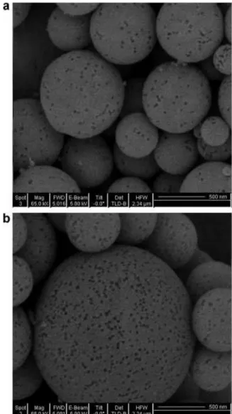
Figure 1 shows SEM images of MoS2/SiO2microspheres (Figure
1a) and SiO2microspheres (Figure 1b), obtained with PSL:SiO2
ratio of 1:2. The particle size for both materials was around 500 nm. Pores with pore size of about 50–100 nm were clearly observed. The sphere shape was formed from the spray drying process. Ultrasonic nebuliser produced small droplets contain-ing PSL microspheres, SiO2 nanoparticles and MoS2 precursor.
These droplets shrank, and the constituent particles and precur-sor assembled into solid through evaporation via capillary forces and electrostatic forces (Sen et al., 2009).
Figure 1. SEM images of (a) MoS2/SiO2microspheres and (b) SiO2
It has been reported that drying rate affected the shape of the solid particles. Too fast drying of the droplets could lead to the formation of non-spherical solids. In this work, non-spherical shaped particles were not observed with SiO2, indicating that the
carrier gas flow rate is not fast enough to trigger the deforma-tion. However, a few doughnut-like particles were observed for MoS2/SiO2as shown in Figure 2. Two different doughnut shapes
were shown in Figure 2a and b. Similar morphologies have been reported in the literature (Leonnard et al., 2002; Sen et al., 2009). Since the carrier gas flow rate for both MoS2/SiO2and pure SiO2
is the same, this deformation was not caused by the drying rate. Sen et al. (2009) found that doughnut-like transition was formed at moderate drying rate during evaporation driven self-assembly of colloidal alumina, which was dependent on the volume frac-tion of the colloids. With high alumina colloid volume fracfrac-tion (5% alumina colloid), spherical shaped materials were obtained, while low alumina volume fraction (2%) led to the formation of doughnut-like particles (Sen et al., 2009). In this work, the same SiO2and PSL concentration was used for both materials. However,
in the synthesis of MoS2/SiO2, certain amount of MoS2precursor
existed in the solution, which might dilute the solution. However, this concentration decrease was extremely minor, which might not be sufficient to contribute to any morphology change. Most possibly, the morphology change was due to the temperature gra-dient at the droplet surface. Sen et al. (2009) explained that the thermophoretic force originated from this temperature gradient moved the colloid at the air–water interface, forming a viscoelas-tic shell of densely packed parviscoelas-ticles, which might buckle after a sol–gel type transition, forming the doughnut-like morphology. In this work, MoS2precursor condensed on the silica nanoparticles
gradually, forming MoS2-coated SiO2. Presence of MoS2 on the
silica surface might have led to a non-uniform temperature dis-tribution, creating a temperature gradient. However, this gradient only occurred in some droplets, thus only a few doughnut-like particles were observed.
The MoS2content in the MoS2/SiO2materials was determined
by EDX. Mo content in the material was found to be 10%, an opti-mal content for a supported MoS2catalyst (van Veen and Colijn,
1993; Meille et al., 1997; Breysse et al., 2003; Egorova and Prins, 2004; Topsoe, 2007).
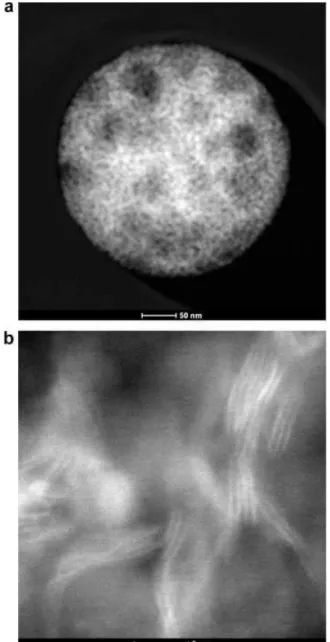
Figure 3a presents the STEM-HAADF image at relatively low magnification of a typical MoS2–SiO2 catalyst particle prepared
by USP method, suggesting that MoS2 (brighter area) is highly
dispersed within the SiO2sphere template. High resolution
STEM-HAADF micrograph (Figure 3b) indicates nanocrystalline MoS2
was grown within the crevices of densely packed template spheres. Plane stacking of 2–7 layers of MoS2 crystallites were
observed, the length of which ranges from 6 to 12 nm. Fur-thermore, the MoS2 interlayer spacing is 6.34 ± 0.3 ˚A, which is
consistent with the XRD measurement.
Figure 4 shows the XRD pattern of MoS2/SiO2. The broad peak
of 2-theta around 24 is attributed to the SiO2. Three broad
diffrac-tion peaks at 2-theta of 14.1◦, 33.6◦ and 59.4◦, are attributed to
the (002), (100) and (110) planes of the poorly crystalline MoS2,
respectively. The corresponding d spacing was 6.4, 2.7 and 1.2 ˚A respectively (Skrabalak and Suslick, 2005). This material might exhibit some low stacking of layers on the SiO2 surface along
different directions, as evidenced from the HRTEM image. The intensity of MoS2diffraction peaks is rather low, suggesting that
the MoS2is well dispersed along the surface of the SiO2.
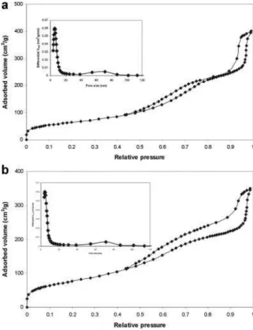
Figure 5 shows the nitrogen isotherms of MoS2/SiO2 (Figure
5a) and SiO2 (Figure 5b). Three steps, at the relative pressure
range of <0.02, 0.5–0.8 and >0.85, were observed on both curves,
Figure 2. SEM images of doughnut-like MoS2/SiO2showing different
morphology (a,b) prepared by USP with a PSL:SiO2ratio of 1:2.
corresponding to micro-, meso- and macropores in the materials. The inset in each figure showed the pore size distribution. The micro-, meso- and macropore volume was calculated from the adsorbed volume obtained by extrapolating the plateau after each step. The porous properties were summarised in Table 1.
The BET surface area of MoS2/SiO2was found to be 235 m2/g,
smaller than that of pure hierarchical SiO2(280 m2/g). The pore
size of MoS2/SiO2 was 5.8 and 68 nm, while for the SiO2
micro-spheres, pore sizes of 4.3 and 70 nm were obtained. This is not unexpected. In the synthesis process, small droplets containing PSL, SiO2nanoparticles and MoS2precursor were formed by the
ultrasonic nebuliser and were taken into the heating zone by the carrier gas; then PSL particles rearranged quickly inside the silica nanoparticles and MoS2precursor depositing on the SiO2
nanopar-ticles during the evaporation of the droplets, forming parnanopar-ticles containing PSL, SiO2 nanoparticles and MoS2precursor stacked
together. The well-ordered PSL particles would occupy fixed posi-tions after the droplets were transformed into solid particles. At higher temperature, PSL were decomposed, leaving ordered pores at their original position. The PSL microspheres used were 50 nm, thus the macropore size created is around this value. Actually ∼70 nm pore size was observed for both MoS2/SiO2and SiO2. This
Table 1. Properties of the hierarchical structure porous MoS2/SiO2and SiO2
MoS2/SiO2 SiO2
Properties PSL:SiO2=1:2 PSL:SiO2=1:4 PSL:SiO2=1:2 PSL:SiO2=1:4
BET (m2/g) 235 191 280 232 Pore size (nm) Meso 5.8 6.8 4.3 4.3 Macro 68 87 70 55 Pore volume (cm3/g) Micro 0.077 0.064 0.080 0.065 Meso 0.270 0.137 0.235 0.220 Macro 0.243 0.245 0.203 0.119 Total 0.590 0.446 0.518 0.404
Figure 3. (a) Overview of a typical MoS2catalyst particle supported on
SiO2template at relative low magnification in STEM-HAADF mode; (b)
high-resolution STEM-HAADF image of the particle with lattice fringe details of MoS2.
which may facilitate the diffusion of asphaltenes to get access to the inner active sites.
The mesopores were created from the packing of SiO2
nanopar-icles and MoS2/SiO2nanoparticles formed in the USP process. In
this work, 8 nm SiO2 nanoparticles were used and the packing
of these nanoparticles into microsphere shape created mesopores, producing SiO2microspheres with mesopore size of 4.3 nm. For
MoS2/SiO2, MoS2 deposited on the SiO2 nanoparticles,
result-ing in increased SiO2 nanoparticle size. Therefore, packing of
larger-sized nanoparticles led to the formation of larger pores. This is what was observed experimentally. The mesopore size of MoS2/SiO2microspheres (5.8 nm) is larger than SiO2(4.3 nm).
The micro-, meso- and macropore volume was calculated by extrapolating the plateaus after each step. The intercept at the
y-axis was the adsorbed N2 volume in gas form. Converting the
adsorbed N2gas volume into liquid N2volume, the pore volume
for each pore size could be obtained. The results are also listed in Table 1. The total pore volume of MoS2/SiO2is larger than that of
SiO2, which is due to the larger mesopore and macropore volumes
of MoS2/SiO2. The microspore volume of MoS2/SiO2and SiO2is
close to each other.
The PSL:silica ratio determined the hierarchical porous struc-ture of the product. Increasing PSL concentration resulted in the formation of brittle spheres that were easily collapsed. Increasing silica nanoparticles concentration produced microspheres with less porosity. Table 1 also presents the results obtained with MoS2/SiO2and SiO2microspheres prepared with a PSL:SiO2ratio
of 1:4. The total pore volume, micro-, meso- and macropore vol-ume were smaller than their corresponding counterparts prepared using a PSL:SiO2 ratio of 1:2. However, the change in pore size
Figure 5. N2adsorption/desorption isotherm of (a) the MoS2/SiO2
microspheres, (b) SiO2microspheres prepared by USP, inset: pore size
distribution from the adsorption section.
with increased SiO2 concentration was different for MoS2/SiO2
and SiO2. For MoS2/SiO2, both mesopore and macropore size
increased with the PSL:SiO2ratio of 1:4. For SiO2, the mesopore
size did not change, while the macropore size decreased. Slight decrease in BET surface area was observed for both materials. This difference might be due to the stacking of PSL, SiO2 and
MoS2precursor, and due to the decomposition of PSL during the
USP process (Iskandar et al., 2001, 2002).
CONCLUSIONS
Hierarchical structured porous MoS2/SiO2microspheres were
suc-cessfully prepared using USP technique with PSL as a template to create the macropores and with silica nanparticles as support to create meso- and micropores. The microspheres had high BET surface area, with macropore size of 68 nm, matching the molec-ular size of asphaltenes, and mesopore size of 5.8 nm. PSL:SiO2
ratio affected the hierarchical porous structure. More PSL pro-duced easily collapsed microspheres and high SiO2concentration
led to a product with less pore volume. The hierarchical structured MoS2/SiO2can facilitate the diffusion of different sized molecules,
and have the potential as catalyst component in extra heavy oil upgrading.
ACKNOWLEDGEMENTS
The authors would like to thank the Government of Canada’s Program for Energy Research and Development, PERD 1.1.3, Petroleum Conversion for Cleaner Air and the Institute for Fuel Cell Innovation, National Research Council of Canada for financial
support. Feihong Nan and Gianluigi A. Botton are grateful to NSERC for a strategic grant supporting this work. TEM work was carried out at the Canadian Centre for Electron Microscopy, a facility supported by NSERC and McMaster University.
REFERENCES
Bang, J. H. and K. S. Suslick, “Applications of Ultrasound to the Synthesis of Nanostructured Materials,” Adv. Mater. 22, 1039–1059 (2010).
Breysse, M., P. Afanasiev, C. Geantet and M. Vrinat, “Overview of Support Effects in Hydrotreating Catalysts,” Catal. Today 86, 5–16 ().
Chang, H., S. J. Kim, H. D. Jang, T. O. Kim and K. Okuyama, “Pore Size-Controlled Synthesis and Characterisation of Nanostructured Silica Particles,” Ultramicroscopy 108, 1260–1265 (2008).
Egorova, M. and R. Prins, “Hydrodesulfurisation of
Dibenzothiophene and 4,6-Dimethyldibenzothiophene Over Sulfided NiMo/ -Al2O3, CoMo/ -Al2O3, and Mo/ -Al2O3
Catalysts,” J. Catal. 225, 417–427 (2004).
Iskandar, F., M. Abdullah and K. Okuyama, “In Situ Production of Spherical Silica Particles Containing Self-Organised Mesopores,” Nano Lett. 1, 231–234 (2001).
Iskandar, F., M. Abdullah and K. Okuyama, “Controllability of Pore Size and Porosity on Self-Organised Porous Silica Particles,” Nano Lett. 2, 389–392 (2002).
Iskandar, F., L. Gradon and K. Okuyama, “Control of the Morphology of Nanostructured Particles Prepared by the Spray Drying of a Nanoparticle Sol,” J. Coll. Inter. Sci. 265, 296–303 (2003).
Lemaire, A. and B. L. Su, “Highly Spongy Hierarchical
Structured Meso–Macrosporous Aluminosilicates With High Tetrahedral Aluminum Content and 3D Interconnectivity From a Single-Source Molecular Precursor
(sec-BuO)2-Al-O-Si(Oet)3: Effect of Silicon Co-Reactant,”
Microp. Mesop. Mater. 142, 70–81 (2011).
Lin, K., O. I. Lebedev, G. Van Tendeloo, P. A. Jacobs and P. P. Pescarmona, “Titanosilicate Beads With Hierarchical Porosity: Synthesis and Application as Expoxidation Catalysts,” Chem. Eur. J. 16, 13509–13518 (2010).
Leonnard, S., J. R. Bartlett, E. Sizgek, K. S. Finnie, Th. Zemb and J. L. Woolfrey, “Role of Interparticle Potential in Controlling the Morphology of Spray Dried Powders From Aqueous Nanoparticle Sols,” Langmuir 18, 10386–10397 (2002). Meille, V., E. Schulz, M. Lemaire and M. Vrinat,
“Hydrodesulfurisation of Alkyldibenzothiophenes Over a NiMo/Al2O3Catalyst: Kinetics and Mechanism,” J. Catal.
170, 29–36 (1997).
Nan, F., C. Song, J. Zhang, R. Hui, J. Chen, C. Fairbridge and G. A. Botton, “STEM HAADF Tomography of Molybdenum Disulfide With Mesoporous Structure,” Chem. Catal. Chem. 3, 999–1003 (2011).
Okuyama, K., M. Abdullah, I. W. Lenggoro and F. Iskanda, “Preparation of Functional Nanostructured Particles by Spray Drying,” Adv. Powder Tech. 17, 587–611 (2006).
Sen, D., D. S. Mazumder, J. S. Melo, A. Khan, S. Bhattyacharya and S. D’Souza, “Evaporation Driven Self-Assembly of a Colloidal Dispersion During Spray Drying: Volume Fraction Dependent Morphological Transition,” Langmuir 25, 6690–6695 (2009).
Skrabalak, S. E. and K. S. Suslick, “Porous MoS2Synthesised by
Ultrasonic Spray Pyrolysis,” J. Am. Chem. Soc. 127, 9990–9991 (2005).
Stevens, S. M., A. R. Loiola, P. Cubillas, L. R. D. da Silva, O. Teraraki and M. W. Anderson, “Hierarchical Porous Materials: Internal Structure Revealed by Argon Ion-Beam Cross-Section Polishing,” HRSEM AFM Solid State Sci. 13, 745–749 (2011). Thill, A. and O. Spalla, “Influence of Templating Latex on Spray
Dried Nanocomposite Powders Studied by Small Angle Scattering,” J. Coll. Inter. Sci. 291, 477–488 (2005). Topsoe, H., “The Role of Co–Mo–S Type Structures in
Hydrotreating Catalysts,” Appl. Catal. A Gen. 322, 3–8 (2007). van Veen, J. A. R. and H. A. Colijn, “On the Formation of Type I
and Type II NiMoS Phases in NiMo/Al2O3Hydrotreating
Catalysts and its Catalytic Implications,” Fuel Proc. Tech. 35, 137–157 (1993).
Wang, X., G. Li, W. Wang, C. Jin and Y. Chen, “Synthesis, Characterisation and Catalytic Performance of Hierarchical TS-1 With Carbon Template From Sucrose Carbonisation,” Microp. Mesop. Mater. 142, 494–502 (2011).
Widiyastuti, W., R. Balgis, F. Iskandar and K. Okuyama, “Nanoparticle Formation in Spray Pyrolysis Under Low-Pressure Conditions,” Chem. Eng. Sci. 65, 1846–1854 (2010).
Yang, X., A. Leonard, A. Lemaire, G. Tian and B. Su, “Self-Formation Phenomenon to Hierarchically Structured Porous Materials: Design, Synthesis, Formation Mechanism and Applications,” Chem. Commun. 47, 2763–2786 (2011).
Manuscript received May 23, 2011; revised manuscript
received October 28, 2011; accepted for publication November 7, 2011.