Publisher’s version / Version de l'éditeur:
Vous avez des questions? Nous pouvons vous aider. Pour communiquer directement avec un auteur, consultez la première page de la revue dans laquelle son article a été publié afin de trouver ses coordonnées. Si vous n’arrivez pas à les repérer, communiquez avec nous à [email protected].
Questions? Contact the NRC Publications Archive team at
[email protected]. If you wish to email the authors directly, please see the first page of the publication for their contact information.
https://publications-cnrc.canada.ca/fra/droits
L’accès à ce site Web et l’utilisation de son contenu sont assujettis aux conditions présentées dans le site LISEZ CES CONDITIONS ATTENTIVEMENT AVANT D’UTILISER CE SITE WEB.
8th Canadian Marine Hydromechanics and Structures Conference [Proceedings],
2007
READ THESE TERMS AND CONDITIONS CAREFULLY BEFORE USING THIS WEBSITE. https://nrc-publications.canada.ca/eng/copyright
NRC Publications Archive Record / Notice des Archives des publications du CNRC :
https://nrc-publications.canada.ca/eng/view/object/?id=4bb2ebb0-2ec0-4623-8408-3c6fd276ef89
https://publications-cnrc.canada.ca/fra/voir/objet/?id=4bb2ebb0-2ec0-4623-8408-3c6fd276ef89
Archives des publications du CNRC
This publication could be one of several versions: author’s original, accepted manuscript or the publisher’s version. / La version de cette publication peut être l’une des suivantes : la version prépublication de l’auteur, la version acceptée du manuscrit ou la version de l’éditeur.
Access and use of this website and the material on it are subject to the Terms and Conditions set forth at
Ship collision mitigation: redesign of an oil taner side-shell
Ship Collision Mitigation: Redesign of an Oil Tanker
Side-shell
Bruce W.T. Quinton
1, 2 1Faculty of Engineering and Applied Science, Memorial University of Newfoundland St. John’s, NL, A1B 3X5, Canada
2
Institute for Ocean Technology, National Research Council Canada St. John’s, NL, A1B 3T5, Canada
Email: [email protected]
A
BSTRACTStructural design has been shown to be an effective tool for reducing collision damage and cargo spill of a struck oil tanker given a collision.
This paper explores the structural redesign of a double-hull oil tanker side-shell in order to improve its collision performance with respect to hull rupture, damaged area, and oil-outflow. In particular, the side-shell plate stiffening arrangement and transverse web frames are redesigned, with weight and structural capacity as design constraints.
Explicit-dynamics numerical models using LS-DYNA show that reducing the structural rigidity of the tanker’s side-shell, while maintaining the same plate stiffening steel weight may: increase the efficiency of the side-shell in converting kinetic collision energy into elastic strain energy; reduce the longitudinal and overall damaged areas; and “compartmentalize” the damage so that residual stresses decrease quickly with radial distance from the point of impact.
1.
I
NTRODUCTIONWith today’s advanced shipboard technology and communications capabilities, ship collisions should be a thing of the past. Indeed, statistics show a decline in the frequency of ship collisions over recent years [8]. However, no matter how sophisticated shipboard technology becomes, ship collisions will always be a reality as long as human error, mechanical failure, and environmental conditions play major roles in shipping. The consequences of ship collisions can be severe for the environment, the ship’s crew, and other stakeholders.
In an attempt to mitigate oil spills, the United States introduced double-hull tanker regulations (U.S. Oil Pollution Act) in 1990 following the Exxon Valdez oil spill in Alaska on March 23, 1989. The International Maritime Organization (IMO) later responded by requiring double-hulls (or their equivalent) for all new build oil tankers.
It is now generally agreed that a ship’s structural design has a major influence on the extent of resulting damage, loss of stability, cargo spill, and residual hull strength [6, 8].
The goal of this paper is to determine if an improvement in collision performance can be made over the “standard” double-hull oil tanker side-shell design. To accomplish this, components of the side-shell structure of a standard double-hull oil tanker were redesigned and their performances compared – individually and as assemblies – to the standard design using explicit dynamics finite element models. Specifically, the plate stiffening arrangement and transverse web frames of a standard wall-sided midship section were redesigned and tested.
It is hoped that this paper will help stimulate further research into “flexible” structural designs and eventually lead to improved crashworthiness for ships in general. Taking a page out of history reminds us that the Vikings were able to cross the Atlantic due to the flexibility of their wooden lapstrake knarrs (longboats) centuries before other peoples.
2.
C
OLLISIONSCollisions are random events and usually occur near shore – especially a port of call where the density of ships in a given area is much higher than on the open ocean. The probability of collision per nautical mile
2 sailed is approximately 2x10⁻⁷, while collision frequency per port call is approximately 4x10⁻⁵ [6]. The types of ships involved in collisions and their relative size, speed, and heading all affect the amount of damage incurred during a collision. Important collision event variables are summarized in Table 1.
Struck Ship Variables
Striking Ship
Variables Other Variables
Design Type Collision Angle
Speed DWT Impact Location
Trim Speed
Draft Bow HEA*
Bow Height Beam Displacement
Draft Trim
* HEA = Half Entrance Angle Table 1: Collision event variables.
For this paper struck-ship design, speed, collision angle, and impact location are independent variables. Striking-ship characteristics are dependent variables found from worldwide ship encounter probabilities, striking-ship speed collision probabilities, and Weibull regressions of worldwide ship hydrostatics data. These probabilities and data were taken from [2] and [7] and analyzed and presented by [1].
2.1
Collision Mechanics
Collision mechanics are usually separated into external and internal mechanics [5]. External mechanics consider rigid body motions and hydrodynamic pressures. Internal mechanics explore structural failure response. To simplify analysis and reduce numerical model run times, external mechanics are not explored in this paper. It is felt this simplification is justified by the scope of the analysis – which is to determine if improvements in structural damage capacity can be made over the standard double-hull design.
2.1.1 Internal mechanics
Internal mechanics are described in terms of shell membrane tension, shell rupture, web frame bending, shear and compression loads, yield strength, failure strain, friction, and crushing and tearing of decks, bottoms and stringers.
Structural failure mechanisms include: plate rupture, in-plane plate crushing and tearing, stiffener buckling and rupture, web frame buckling, stringer buckling, and crushing of structural joins. Note that in this paper, plastic deformation is not considered a failure
mechanism in-and-of itself. Failure is considered to have occurred when a structural member has lost the ability to carry load. Plastically deformed structures exhibit an increasing capacity to carry load up to the point of failure.
2.1.2 Internal mechanics analysis method
Non-linear finite element modeling (FEM) was used exclusively for these tests. Non-linear FEM is the norm for collision analyses [8], and provides the most accurate predictions of collision energy, loads, stresses and material rupture/failure.
Please note that the non-linear FE models presented in this paper have not been calibrated against physical experiments and are therefore not meant to make accurate predictions of actual damage capacity for the vessels involved. Instead, care was taken to ensure that the numerical models were consistent with each other in all respects save structural design, so that comparisons of structural performance between the designs could be made.
2.2
Collision Scenario
The struck-ship was chosen to be a 160,000 DWT double-hull oil tanker. This particular size oil tanker was chosen because it represents a significant portion of new build standard oil tankers. As well, because of its large size it has the potential to spill vast quantities of oil should an unfortunate situation arise. Struck-ship speed was chosen to be zero. This was done to eliminate raking of the striking-ship bow along the struck-ship hull in order to simplify the analysis. Coincidentally, analysis of worldwide collision data shows that struck-ships are most frequently moored or at anchor during collisions with other ships [6].
Striking-ship type was chosen from worldwide ship statistics. A tanker will most likely encounter a freighter type vessel (42.4% chance), and further, there is a 72% chance that the striking-ship will be a 10,000 DWT freighter [1]. The striking-ship will most likely not be travelling at its service speed during a collision because collisions are most probable near a port of call where vessels are transiting much more slowly, and the striking-ship usually tries to slow down before it strikes the other ship. From worldwide collision data [6], there is a 22.5% chance that the striking-ship will impact the struck-ship at 2 knots, 12% at 5 knots, and 7% at 9 knots.
Striking-ship hydrostatics (Table 2) were found from Weibull regressions of worldwide ship data [6].
Weibull
Regression Coefficient Power
Result for 10 kDWT LBP [m] 6.9270 0.3249 138 Beam [m] 1.7215 0.2725 21 Draft [m] 0.4744 0.3197 9 Bow Height [m] 0.7406 0.3211 14 Bow HEA [DEG] ~ ~ 20 Table 2: Striking-ship hydrostatics. The Weibull regression equation is given by:
Based on the length between perpendiculars, beam, and draft, the striking-ship displacement was estimated to be 25000 [Tonnes]. Collision angle was chosen to be 90 degrees (orthogonal collision) with the struck-ship, and strike location was chosen to be at amidships. These values represent the worst-case damage scenario, and provide the most computationally simplistic model.
As mentioned above, external collision mechanics are ignored for this project. Hence, the struck-ship is held rigidly in place (Figure 1), and the struck- and striking-ships’ added mass, hydrostatic pressure, and dynamic trim are neglected. Both struck and striking-ships are assumed to be on even keel before, during, and after the collision.
Figure 1: Collision scenario.
3.
C
OMPONENTR
EDESIGNThe plate stiffening arrangement and the transverse web frames were the focus of the component redesigns. Goals influencing the component redesign were: adding structural flexibility; the maximization of structural capacity; minimization of additional weight; and “compartmentalization” of damage and residual stress/strain (i.e. smaller damaged area, and thus be easier to repair).
3.1
Representative Side-shell Section
Standard designs for the plate stiffening arrangement and transverse web frames were taken from the
wall-sided portion of the midships section between the two stringers (Figure 2). This section was chosen to be representative of the tanker, for the whole numerical model, because it would take the most damage for the given collision scenario.
Figure 2: Representative section of a standard double-hull tanker side-shell at amidships.
3.2
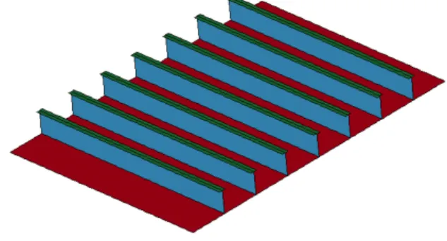
Plate Stiffening Arrangement
The standard plate stiffening arrangement design is shown in Figure 3. This section is bounded by stringers on the top and bottom, and transverse web frames on either side. The plate dimensions are 4.8 [m] longitudinal, and 6.8 [m] vertical. The stiffener spacing is 850 [mm].
Figure 3: Standard plate stiffening arrangement. The plate’s longitudinal stiffeners are T-stiffeners. The dimensions for these stiffeners are given in Figure 4.
Figure 4: Standard T-longitudinal stiffener dimensions.
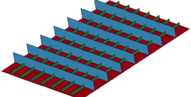
4 3.2.1 Redesign of plate stiffening arrangement The idea for the redesigned plate stiffening arrangement arose from examination of one of the side-shell failure mechanisms; that is, rupture and tearing of the hull plating. The top-deck at the bow of the striking-ship is like a knife, and tends to shear (tear) through the struck-ship’s hull plating in the longitudinal direction. Once the initial longitudinal tear in the plating is made, the only structural obstacles present to stop the tearing in the longitudinal direction are the transverse web frames. The conceptual redesign involves taking the flanges off the longitudinal T-stiffeners and running them vertically along the plate, forming a lattice of stiffeners (Figure 5). This stiffening arrangement satisfies the minimization of steel-weight design constraint because no extra steel is used. It is simply a rearrangement of steel already present in the ship.
Figure 5: Lattice plate stiffening arrangement. In practice, it is not as simple as removing the stiffener flanges and welding them vertically to the plate because the plate section is not square. The optimal steel rearrangement – with respect to stiffener spacing, thickness, and height – could be the subject of another study. For the purposes of this paper, the horizontal stiffener spacing, height, and thickness were chosen equal to the original T-stiffener web values. The height of the vertical stiffeners was chosen to be equal to the original T-stiffener flange-width. The number of vertical stiffeners was chosen to be equal to the number of horizontal stiffeners (i.e. 7). This gave a vertical stiffener spacing of 600 [mm] and a thickness of approximately 15 [mm].
3.3
Transverse Web Frames
The standard transverse web frames are vertically stiffened pieces of thick flat steel. They are very rigid and tend to absorb load that would otherwise spread throughout the rest of the ship structure. The standard transverse web frames modeled in this report are based on the representative section of the double-hull side-shell as outlined above. For simplicity and speed of numerical modeling, the transverse web frame
models do not include holes for longitudinal stiffeners to pass through.
3.3.1 Redesigned transverse web frames
The transverse web frame redesign centres on the idea that flexible transverse web frames would provide a softer response to collision loads and spread collision energy throughout the rest of the ship’s structure, while retaining a large structural capacity of their own. In order to make the transverse web frames more flexible, they were redesigned as Y-springs (shown with stringers (blue) in Figure 6). The tail of the Y-spring is attached to the inner hull, while the ends of the fork of the Y-spring are attached to the outer hull. For simplicity, no investigation of the effect of the “fork angle” was made. The forks meet at a 90o angle.
Figure 6: Redesigned transverse web frame. This web frame may seem structurally similar to Ludophy’s [4] Y-shaped support web, but those support webs were not transverse web frames; they were longitudinal and also incorporated a flange where the fork of the Y meets the central web.
4.
N
ON-
LINEARF
INITEE
LEMENTM
ODEL Non-linear explicit dynamics finite element modeling (FEM) is the basis for comparison of the standard and redesigned side-shell components and their assemblies. LS-DYNA [3] was used to solve these numerical models.SOLID164 elements are used for the non-deformable striking-ship structure. SOLID164 is an 8-node brick element, but for these analyses, the degenerate 4-node tetrahedral version is used for ease of meshing. This is justified because all SOLID164 elements are rigid elements.
SHELL163 elements are used for all deformable structures. SHELL163 is a 4-node planar quadrilateral element. The default element formulation (Belytschko-Tsay with reduced
integration) is used for computational efficiency. A shear correction factor of SHRF=5/6 is used along with 5 through-thickness integration points.
The “Automatic General” contact algorithm is used exclusively in these models. “Automatic” implies that the outside normal for each contact surface is automatically determined for all element contact. This allows random contact between all elements to be accounted for. The element contact coefficient of friction, , is based on the Coulomb friction model and is dependent on the relative velocity of the elements in contact:
where: = static friction coeff. = dynamic friction coeff.
= contact relative velocity = exponential decay coeff.
FS and FD values used are for wet steel to mild-steel contact as reported in [6] and are: FS = 0.7, FD= 0.3 and DC = 7.0.
The material model is based on ABS grade AH36 steel. A kinematic hardening, bilinear stress-strain material model (LS-DYNA material model 003-Plastic Kinematic) is used to model plastic steel deformation. This model simulates plastic deformation through linear interpolation between yield stress and failure strain. The slope of this line is called the Tangent Modulus (Etan) or Plastic Modulus,
and is input with the other material properties. Material strain rate dependency is incorporated using the Cowper-Symonds model which calculates a dynamic yield stress, , by scaling the static yield stress, , with a strain-rate dependent factor [3] given by:
where: = strain rate
C, P = Cowper-Symonds parameters
Failure strain was also taken from literature. Tests have shown that the experimental failure strain for mild steel is around 30-45% elongation. Recent research has shown that the FE material model failure strain input should reflect finite element mesh size. It is agreed that the FEM failure strain should decrease with increasing FE mesh size [6]. Due to a similar mesh size, the failure strain for these models was chosen to be fail=0.1 after [6].
The material model properties are given in Table 3.
Table 3: Material model properties. Density [kg/m3] ρ 7.85E+03 Young's Modulus [Pa] Ex 2.10E+11
Poisson’s Ratio ν 0.303
Yield Stress [Pa] σy 3.55E+08
Steel Tangent Modulus [Pa] Etan 1.00E+09
Plastic Strain to Failure fail 0.1
Cowper-Symmonds Strain Rate
Parameter [Hz] C 40.4
Cowper-Symmonds Strain Rate
Parameter P 5
Identical values, as required, were used for the rigid material model (LS-DYNA material model 020-Rigid).
4.1
Plate Stiffening Arrangement
Static structural capacity tests were carried out on the standard and lattice plate stiffening arrangements. Because these tests are static capacity tests (i.e. no impact), friction and strain rate effects are not modeled. Both geometries were meshed with an average element area of 0.0025 [m2]. Due to the fine mesh density, the material failure strain was changed from 0.10 to 0.40. The models are constrained in all degrees of freedom at their plate and stiffener edges, simulating being welded to the transverse web frames (longitudinally) and the stringers (vertically). An increasing pressure load (05 [MPa]) was applied to the plate (opposite side from the stiffeners) over 10 seconds.
4.1.1 Standard plate stiffening arrangement The standard plate stiffening arrangement geometry is given in Figure 3. This model was meshed with a total of 22,464 shell elements and withstood 3.9 [MPa] (Figure 7), after which it failed.
Figure 7: Max load for standard plate stiffening arrangement.
6 4.1.2 Lattice plate stiffening arrangement
The lattice plate stiffening arrangement geometry is given in Figure 3. This model was meshed with a total of 23,250 shell elements and withstood 3.75 [MPa] (Figure 8), after which it failed.
Figure 8: Max load for lattice plate stiffening arrangement.
4.1.3 Comparison
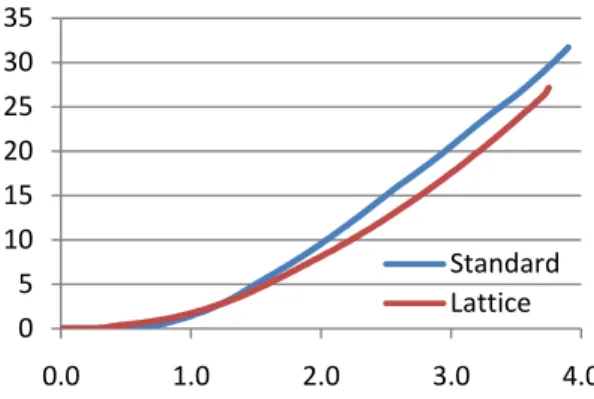
The lattice design can support 96% of the standard design’s failure load. Figure 9 shows the load displacement curves for the centre of the plates for both designs. This plot suggests that lattice geometry has a similar, but somewhat lower overall structural capacity than the standard design; it starts to plastically deform at about half the load of the standard design; and has an overall stiffness that is greater than the standard design (i.e. average slope is greater).
Figure 9: Load [MPa] vs. plate centre displacement [m].
Figure 10 suggests that the lattice design absorbs slightly less energy than the standard design, but starts absorbing energy at about half the load compared with the standard design.
Figure 10: Internal energy [MPa] vs. load [MPa]. Overall, the lattice plate stiffening arrangement has a slightly lower load capacity, but is “softer” in that it starts to deform and absorb energy at about half the load of the standard design.
4.2
Transverse Web Frames
The transverse web frame components were not modeled and compared individually. This is because the outer hull plating is an integral part of the Y-spring component design; unlike the standard design. A load capacity comparison test is not possible for the Y-spring design because the fork “arms” would simply bend independently of each other, and support comparatively little load.
4.3
Side-shell Assemblies and Tests
As mentioned above, the test scenario is an orthogonal collision at amidships between a 160 kDWT double-hull tanker (struck ship) and a 10 kDWT freighter (striking ship) moving in surge at two speeds: 2 and 5 knots. The standard and redesigned components were assembled into standard and redesigned “infinite” wall models, respectfully, for these tests (the standard “infinite wall” assembly is shown on the left side in Figure 11). These infinite wall assemblies are composed of standard and redesigned representative sections (see Figure 2) repeated vertically and longitudinally. Inner and outer hull plating, stringers, transverse web framing, and plate stiffening arrangements are all modeled using deformable shell elements of the appropriate thickness. The infinite side shell models are constrained at their extremities in all degrees of freedom. No degenerate triangular elements were used in these models.
The striking ship model is a bulbous-bow freighter. It is a rigid body composed entirely of 1828 solid tetrahedral elements (right side in Figure 11).
0.0 0.5 1.0 1.5 2.0 2.5 3.0 3.5 4.0 0.0 0.5 1.0 Standard Lattice 0 5 10 15 20 25 30 35 0.0 1.0 2.0 3.0 4.0 Standard Lattice
Figure 11: Infinite standard double-hull side-shell and freighter models.
Inertial properties of the striking-ship model are: translation mass = 25x106 [kg] and initial velocity = 2 or 5 knots. Mass moments of inertia are irrelevant as the only free rigid body degree of freedom is striking ship surge. No other forces or accelerations were applied to the model.
4.3.1 2 knot collision results and comparison For the 2 knot collision test, the striking-ship did not penetrate the outer hull of the standard assembly, and rebounded away. The maximum residual side-shell deflection (i.e. depth of resulting dent) is 0.335 [m]. Figure 12 shows the residual equivalent stress distribution after the collision; all of the standard assembly retains some residual stress.
Figure 12: Residual von Mises stress distribution for standard assembly – 2 knot collision. The 2 knot collision did not penetrate the outer hull of the redesigned assembly either, and again, the striking-ship rebounded away. The maximum residual side-shell deflection is 0.017 [m]. Figure 13 shows the residual equivalent stress distribution after the collision. Most of the redesigned assembly has little to no residual stress. All significant damage is compartmentalized around the impact zone (with the exception of boundary effects).
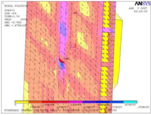
Figure 13: Residual von Mises stress distribution for redesigned assembly – 2 knot collision. 4.3.2 5 knot collision results and comparison The 5 knot collision penetrated the outer and inner hulls of the standard assembly and the striking ship penetrated 0.5 metres past the inner hull (Figure 14). Again residual stress was present throughout the assembly.
Figure 14: Residual von Mises stress distribution for standard assembly – 5 knot collision. The 5 knot collision penetrated the outer hull of the redesigned assembly, but not the inner hull (Figure 15). Residual stress was again compartmentalized to the impact zone.
Figure 15: Residual von Mises stress distribution for redesigned assembly – 2 knot collision.
8
5.
C
OMPARISON ANDA
NALYSIS Neither side-shell structure was penetrated by the striking ship for the 2-knot collision test. For the 5 knot collision test, both inner and outer hulls were breached for the standard assembly, but only the outer hull was breached for redesigned assembly. The overall residual damage extents for the standard assembly were greater than for the redesigned assembly, for both collision speeds. The permanent set (residual plate deflection) is much higher for the standard assembly than for the redesigned assembly, for both collision speeds. This is an interesting result because it implies that more plastic work was done in the standard shell than in the redesigned shell. This in turn means that the redesigned side-shell was more efficient than the standard side-side-shell in converting collision energy into elastic strain energy (i.e. load was shared throughout more structure). This is a benefit because less overall structural damage occurred in the redesigned side-shell. The longitudinal stress for the redesigned assembly is confined to a relatively small area compared with the standard assembly. While the residual stress is higher at the collision impact area for the redesigned side-shell case, the residual stress surrounding the impact area is much lower than for the standard side-shell. This, coupled with a decrease in longitudinal damage over the standard side-shell implies that the redesigned side-shell probably outperforms the standard side-sell regarding oil-outflow performance, as oil-oil-outflow has been shown to be dependent on longitudinal damage [6].The usefulness of the lattice plate stiffening design for impeding hull rupture has not been uniquely evaluated because it was tested in combination with the Y-spring design. Further testing is required to examine the effectiveness of the lattice design by itself.
6.
C
ONCLUSIONThese results imply that increasing the structural flexibility of a double-hull oil tanker side-shell, while maintaining the same volume of plate stiffening structural steel, may reduce the longitudinal and overall damaged area, and compartmentalize residual damage allowing for more efficient repair.
A
CKNOWLEDGEMENTSThe author would like to thank Dr. Brian Veitch, Dr. Claude Daley, and Dr. Shawn Kenny of Memorial University’s Department of Engineering and Applied Science; and Dr. Robert Gagnon and Mr. Gilbert Wong of the Institute for Ocean Technology.
R
EFERENCES[1]. Brown, A.J. 2002. Collision Scenarios and Probabilistic Collision Damage. Marine Structures 15. Pp. 335–364.
[2]. Lloyds. 1993. Lloyds Worldwide Ship data. Provided by MARAD.
[3]. LSTC. 2007. LS-DYNA Keyword User’s Manual Volumes I and II. Version 971. May.
http://www.lstc.com/pdf/ls-dyna_971_manual_k.pdf
[4]. Pedersen, P.T. 1995. Collision and grounding mechanics, WEMT, The Danish Society of Naval Architects and Marine Engineers.
[5]. Ludolphy, H. 2002. The Unsinkable Ship – Development of the Y-Shape Support Web. Royal Schelde Shipyard. The Netherlands. [6]. Sajdak, J.A.W., and A.J. Brown. 2004. Modeling
Longitudinal Damage in Ship Collisions. Department of Aerospace and Ocean Engineering. Virginia Polytechnic Institute and State University. Ship Structure Committee Report SR-1426. October.
[7]. Sandia National Laboratories. 1998. Data and Methods for the Assessment of the Risks Associated with the Maritime Transport of Radioactive Materials Results of the Searam Program Studies. Report SAND98-1171/2. Albuquerque, NM.
[8]. Wang, G., C. Ji, P. Kujala, S.-Gab Lee, A. Marine, J. Sirkar, K. Suzuki, P.T. Pedersen, A.W. Vredeveldt, V. Yuriy. 2006. Committee V.1: Collision and Grounding. 16th International Ship and Offshore Structures Congress. Southampton, UK. 20-25 August.