Publisher’s version / Version de l'éditeur:
Vous avez des questions? Nous pouvons vous aider. Pour communiquer directement avec un auteur, consultez la
première page de la revue dans laquelle son article a été publié afin de trouver ses coordonnées. Si vous n’arrivez
Questions? Contact the NRC Publications Archive team at
PublicationsArchive-ArchivesPublications@nrc-cnrc.gc.ca. If you wish to email the authors directly, please see the first page of the publication for their contact information.
https://publications-cnrc.canada.ca/fra/droits
L’accès à ce site Web et l’utilisation de son contenu sont assujettis aux conditions présentées dans le site
LISEZ CES CONDITIONS ATTENTIVEMENT AVANT D’UTILISER CE SITE WEB.
Research Report (National Research Council of Canada. Institute for Research in Construction), 2006-05-12
READ THESE TERMS AND CONDITIONS CAREFULLY BEFORE USING THIS WEBSITE.
https://nrc-publications.canada.ca/eng/copyright
NRC Publications Archive Record / Notice des Archives des publications du CNRC :
https://nrc-publications.canada.ca/eng/view/object/?id=bc7fe8c7-890d-43be-b767-fa89a4bc8ace https://publications-cnrc.canada.ca/fra/voir/objet/?id=bc7fe8c7-890d-43be-b767-fa89a4bc8ace
Archives des publications du CNRC
For the publisher’s version, please access the DOI link below./ Pour consulter la version de l’éditeur, utilisez le lien DOI ci-dessous.
https://doi.org/10.4224/20377598
Access and use of this website and the material on it are subject to the Terms and Conditions set forth at
Results of the HAMSTAD Benchmarking Exercises Using hygIRC 1D Version 1.1
Results of the HAMSTAD Benchmarking Exercises Using
hygIRC 1-D version 1.1
I R C - R R - 2 2 2
C o r n i c k , S .
May 12, 2006
Results of the HAMSTAD Benchmarking Exercises
Using
hygIRC 1-D version 1.1
National Research Council of Canada Institute for Research in Construction Research Report IRC-RR-222
Author: Steve Cornick Research Officer Date: May 12, 2006 Pages: 93
Table of Contents
List of Tables ... ii
List of Figures ... ii
Executive Summary ... 6
Introduction and Scope ... 6
The Exercises ... 7
Benchmark 1 – Insulated roof... 7
Benchmark 2 – Analytical case... 7
Benchmark 3 – Lightweight wall ... 8
Benchmark 4 – Response Analysis... 8
Benchmark 5 – Capillary active inside insulation... 8
Error Analysis ... 9
Band of acceptance ... 9
Benchmark 1 Results ... 11
Input ... 11
Results ... 16
Confidence Limits and Error Analysis... 17
Benchmark 2 Results ... 22
Input ... 22
Results ... 27
Confidence Limits and Error Analysis... 28
Benchmark 3 Results ... 30
Input ... 30
Results ... 38
Confidence Limits and Error Analysis... 39
Benchmark 4 Results ... 44
Input ... 44
Results ... 52
Confidence Limits and Error Analysis... 60
Benchmark 5 Results ... 62
Input ... 62
Results ... 67
Confidence Limits and Error Analysis... 67
Summary ... 68 References... 68 Appendix 1... 70 Appendix 2... 75 Appendix 3... 78 Appendix 4... 83 Appendix 5... 88
List of Tables
Table 1 tp as a function of the number of observations, n, and total risk, p, that the band
of acceptance does not contain the true solution... 10
Table 2 Correlation coefficient, x,y, and F-test statistic for hygIRC 1-D and the original HAMSTAD models at 100, 300, and 1000 hours... 28
Table 3 – Coefficients for determining wall average pressure coefficient, Cp. ... 31
Table 4 Table of wind speeds used for Benchmark 3... 33
Table 5 Relative Humidites corresponding to vapour pressures specified by HAMSTAD. ... 45
Table 6 Wind and rainfall settings corresponding to the specified HAMSTAD moisture loading ... 47
List of Figures
Figure 1 Construction details for the benchmark “Insulated roof.”... 7Figure 2 Construction details for the benchmark “Analytical Solution.”... 7
Figure 3 Description of the boundary conditions for benchmark “Lightweight wall.”... 8
Figure 4 External and internal climatic loads. Heat load from exterior is given in terms of differences between external equivalent, Teq,e, and internal, Ta,i, air temperature. Moisture load at external side is given as a rain flux, and on internal side as the vapour partial pressure, pa,i at constant temperature. ... 9
Figure 5 Description of the boundary conditions for benchmark “Capillary active.” ... 9
Figure 6 Benchmark 1 Exterior Input Screen... 12
Figure 7 Benchmark 1 Interior Input Screen... 12
Figure 8 Benchmark 1 Structure Input Screen. ... 14
Figure 9 Benchmark 1 Initial Conditions Input Screen... 14
Figure 10 Benchmark 1 Boundary Behaviour Input Screen... 15
Figure 11 Benchmark 1 Air Diffusion Input Screen. ... 15
Figure 12 Benchmark 1 Simulation Parameters Dialog Box. ... 16
Figure 13 hygIRC 1-D Results, 99.9% confidence grade, and averaged results for total moisture content in load bearing material, 1st year... 17
Figure 14 hygIRC 1-D Results, 99.9% confidence grade, and averaged results for total moisture content in insulating material, 1st year. ... 17
Figure 15 hygIRC 1-D Results, 99.9% confidence grade, and averaged results for total moisture content in insulating material, 1st year, 8000 to 8760 hours. ... 18
Figure 16 hygIRC 1-D Results, 99.9% confidence grade, and averaged results for total moisture content in load bearing material, 2nd year... 18
Figure 17 hygIRC 1-D Results, 99.9% confidence grade, and averaged results for total moisture content in insulating material, 2nd year. ... 19
Figure 18 hygIRC 1-D Results, 99.9% confidence grade, and averaged results for total moisture content in load bearing material, 3rd year. ... 19
Figure 19 hygIRC 1-D Results, 99.9% confidence grade, and averaged results for total
moisture content in insulating material, 3rd year... 20
Figure 20 hygIRC 1-D Results, 99.9% confidence grade, and averaged results for total moisture content in load bearing material, 4th year. ... 20
Figure 21 hygIRC 1-D Results, 99.9% confidence grade, and averaged results for total moisture content in insulating material, 4th year... 21
Figure 22 hygIRC 1-D Results, 99.9% confidence grade, and averaged results for total moisture content in load bearing material, 5th year. ... 21
Figure 23 hygIRC 1-D Results, 99.9% confidence grade, and averaged results for total moisture content in insulating material, 5th year... 22
Figure 24 Benchmark 2 Exterior Input Screen... 23
Figure 25 Benchmark 2 Constant Conditions Dialog Box. ... 23
Figure 26 Benchmark 2 Interior Input Screen... 24
Figure 27 Benchmark 2 Interior Conditions Dialog Box. ... 24
Figure 28 Benchmark 2 Structure Input Screen. ... 25
Figure 29 Benchmark 2 Initial Conditions Input Screen... 25
Figure 30 Benchmark 2 Boundary Behaviour Input Screen... 26
Figure 31 Benchmark 2 Air Diffusion Input Screen. ... 27
Figure 32 Benchmark 2 Simulation Parameters Dialog Box. ... 27
Figure 33 hygIRC 1-D Results, 99.9% confidence grade, and averaged results for total water content in the material after 100 hours. ... 28
Figure 34 hygIRC 1-D Results, 99.9% confidence grade, and averaged results for total water content in the material after 300 hours. ... 29
Figure 35 hygIRC 1-D Results, 99.9% confidence grade, and averaged results for total water content in the material after 1000 hours. ... 29
Figure 36 Method for calculating the wall angle, ... 32
Figure 37 Variation of wind pressure coefficient, Cp, with wind direction, derived from ASHRAE Handbook of Fundamentals, [2]. The curve is taken from Swami, H. V. and Chandra, S. [3]... 32
Figure 38 Benchmark 3 Exterior Input Screen... 34
Figure 39 Benchmark 3 Interior Input Screen... 35
Figure 40 Benchmark 3 Interior Conditions Dialog Box. ... 35
Figure 41 Benchmark 3 Structure Input Screen. ... 36
Figure 42 Benchmark 3 Initial Conditions Input Screen... 37
Figure 43 Benchmark 3 Boundary Behaviour Input Screen... 37
Figure 44 Benchmark 3 Air Diffusion Input Screen. ... 38
Figure 45 Benchmark 3 Simulation Parameters Dialog Box. ... 38
Figure 46 hygIRC 1-D Results, 99.9% confidence grade, and averaged results for total water content in Benchmark 3 material, 50mm deep. ... 39
Figure 47 hygIRC 1-D Results, 99.9% confidence grade, and averaged results for total water content in Benchmark 3 material, 100mm deep. ... 39
Figure 48 hygIRC 1-D Results, 99.9% confidence grade, and averaged results for total water content in Benchmark 3 material, 150mm deep. ... 40 Figure 49 hygIRC 1-D Results, 99.9% confidence grade, and averaged results for total
Figure 50 hygIRC 1-D Results, 99.9% confidence grade, and averaged results for total
water content in Benchmark 3 material, 190mm deep. ... 41
Figure 51 hygIRC 1-D Results, 99.9% confidence grade, and averaged results for temperature in Benchmark 3 material, 50mm deep... 41
Figure 52 hygIRC 1-D Results, 99.9% confidence grade, and averaged results for temperature in Benchmark 3 material, 100mm deep... 42
Figure 53 hygIRC 1-D Results, 99.9% confidence grade, and averaged results for temperature in Benchmark 3 material, 150mm deep... 42
Figure 54 hygIRC 1-D Results, 99.9% confidence grade, and averaged results for temperature in Benchmark 3 material, 170mm deep... 43
Figure 55 hygIRC 1-D Results, 99.9% confidence grade, and averaged results for temperature in Benchmark 3 material, 190mm deep... 43
Figure 56 Exterior temperature and relative humidity profile... 45
Figure 57 Exterior wind speed and horizontal rainfall profile. ... 48
Figure 58 Benchmark 4 Exterior Input Screen... 48
Figure 59 Benchmark 4 Interior Input Screen. ... 49
Figure 60 Benchmark 4 Structure Input Screen. ... 50
Figure 61 Benchmark 4 Initial Conditions Input Screen... 50
Figure 62 Benchmark 4 Boundary Behaviour Input Screen... 51
Figure 63 Benchmark 4 Air Diffusion Input Screen. ... 52
Figure 64 Benchmark 4 Simulation Parameters Dialog Box. ... 52
Figure 65 Time history of the moisture content, Kg/m3, on the exterior surface for all models tested in Benchmark 4... 53
Figure 66 Time history of the moisture content, Kg/m3, on the interior surface for all models tested in Benchmark 4... 53
Figure 67 Time history of the temperature, ºC, on the exterior surface for all models tested in Benchmark 4... 54
Figure 68 Time history of the temperature, ºC, on the exterior surface for all models tested in Benchmark 4... 54
Figure 69 Moisture content profile through the Benchmark 4 wall at 12 hours for all models tested... 55
Figure 70 Moisture content profile through the Benchmark 4 wall at 24 hours for all models tested... 55
Figure 71 Moisture content profile through the Benchmark 4 wall at 48 hours for all models tested... 56
Figure 72 Moisture content profile through the Benchmark 4 wall at 54 hours for all models tested... 56
Figure 73 Moisture content profile through the Benchmark 4 wall at 78 hours for all models tested... 57
Figure 74 Moisture content profile through the Benchmark 4 wall at 96 hours for all models tested... 57
Figure 75 Moisture content profile through the Benchmark 4 wall at 120 hours for all models tested... 58
Figure 76 Temperature profile through the Benchmark 4 wall at 24 hours for all models tested. ... 58
Figure 77 Temperature profile through the Benchmark 4 wall at 78 hours for all models
tested. ... 59
Figure 78 Temperature profile through the Benchmark 4 wall at 96 hours for all models tested. ... 59
Figure 79 hygIRC 1-D Results, 99.9% confidence grade, and averaged results for total water content on the exterior surface of the Benchmark 4 wall. ... 60
Figure 80 hygIRC 1-D Results, 99.9% confidence grade, and averaged results for total water content on the interior surface of the Benchmark 4 wall... 60
Figure 81 hygIRC 1-D Results, 99.9% confidence grade, and averaged results for temperature on the interior surface of the Benchmark 4 wall. ... 61
Figure 82 hygIRC 1-D Results, 99.9% confidence grade, and averaged results for temperature on the interior surface of the Benchmark 4 wall. ... 61
Figure 83 Benchmark 5 Exterior Input Screen... 62
Figure 84 Benchmark 5 Constant Conditions Dialog Box. ... 63
Figure 85 Benchmark 5 Interior Input Screen... 63
Figure 86 Benchmark 5 Interior Conditions Dialog Box. ... 64
Figure 87 Benchmark 5 Structure Input Screen. ... 64
Figure 88 Benchmark 5 Initial Conditions Input Screen... 65
Figure 89 Benchmark 5 Boundary Behaviour Input Screen... 66
Figure 90 Benchmark 5 Air Diffusion Input Screen. ... 66
Figure 91 Benchmark 5 Simulation Parameters Dialog Box. ... 67
Figure 92 hygIRC 1-D Results, 99.9% confidence grade, and averaged results for water content, Kg/m3, profile through the Benchmark 5 wall. ... 67
Figure 93 hygIRC 1-D Results, 99.9% confidence grade, and averaged results for relative humidity, %, profile through the Benchmark 5 wall... 68
Executive Summary
The 5 Benchmark exercises specified in the HAMSTAD EU work project (HAMSTAD WP2) were completed using an unmodified version of hygIRC 1-D, version 1.1, available for sale to the public. The objective of the work was to successfully complete the exercises using an “out of the box” version of hygIRC 1-D. All the benchmarks were successfully completed. The results consistently were within the 0.1% confidence band of acceptance specified or close to the original results of the HAMSTAD project where it was not possible to estimate the confidence limits. Successful completion of these exercises using an unmodified version of hygIRC demonstrates the reliability and robustness of hygIRC 1-D version 1.1 as a hygrothermal simulation tool.
Introduction and Scope
The objective of this work was to perform the HAMSTAD benchmark exercises using
hygIRC 1-D version 1.1. The goal was to come as close as possible to original
HAMSTAD results, keeping within the specified confidence limits, using hygIRC 1-D without modifying the basic kernel. The benchmark exercises were attempted using an unmodified version of hygIRC 1-D released for sale to the public; i.e. tested “out of the box.” The results are compared with the original HAMSTAD results submitted to the HAMSTAD EU work project (HAMSTAD WP2) in 2000. Any significant differences between the hygIRC 1-D and original the HAMSTAD benchmark results are explained. The input parameters for each hygIRC run are provided. Explanations of how the boundary conditions (exterior and interior) input files were generated are provided where appropriate. The determination of initial conditions is also explained where required. The goal was to enable hygIRC users to duplicate the benchmark exercises. All of the available input files and results are available from the Institute for Research in Construction1. This documentation and the summary of the exercises assume a considerable degree of experience in working with hygIRC 1-D version 1.1.
The scope and purpose of the HAMSTAD exercises are presented briefly here. The following text is taken from Hagentoft et. al. [1] “The HAMSTAD exercises comprise five numerical benchmark cases for the quality assessment of simulation models for one-dimensional heat, air and moisture (HAM-) transfer. In one case, Benchmark 2, the analytical solution is known. In the remaining four cases, consensus solutions were found, with good agreement between different HAM models. The original HAMSTAD work was undertaken as part of EU-initiated project for standardization of HAM calculation methods (HAMSTAD WP2). It was suggested that the benchmarks be used as references in the assessment of existing and new software packages.”
1
Available on the hygIRC 1D website, http://irc.nrc-cnrc.gc.ca/bes/software/hygIRC/index_e.html
The Exercises
Benchmark 1 – Insulated roof
This benchmark deals with interstitial condensation occurring at the contact surface between two materials. The construction, from lowest x-coordinate (external side) to the highest, is built up as follows; vapour tight seal, 100 mm load bearing material and 50 mm thermal insulation. The materials have different thermal and moisture properties – the load bearing material is capillary active, while the insulation is hygroscopic but capillary non-active (infinite resistance to liquid flow), and thermal conductivities differ by a factor 50 (at dry conditions). The structure is perfectly airtight. Complete details for this exercise, taken from HAMSTAD WP2, are appended as Appendix 1. A schematic is shown in Figure 1.
Figure 1 Construction details for the benchmark “Insulated roof.” Benchmark 2 – Analytical case
This benchmark deals with the moisture redistribution in a homogeneous layer under isothermal conditions. The thickness of the layer is 200 mm. The layer is initially in moisture equilibrium with the ambient air, which has a constant relative humidity. Moisture movement is caused by a sudden but different change in relative humidity in the surroundings. The structure is perfectly airtight. The case can be solved analytically. The simulation covers 1000 hours. Complete details for this exercise taken from HAMSTAD WP2 are appended as Appendix 2. A schematic is shown in Figure 2.
Benchmark 3 – Lightweight wall
The third benchmark deals with air transfer through single 200 mm thick layer. Moisture transfer is caused mainly by airflow, but also by the moisture and temperature gradients across the layer. The external side (x=200 mm) is vapour tight but air-open. The simulation time is 100 days. During the first 20 days there is air exfiltration, which then changes to air infiltration. Details about boundary conditions are shown below. Complete details for this exercise taken from HAMSTAD WP2 are appended as Appendix 3. A schematic is shown in Figure 3.
Figure 3 Description of the boundary conditions for benchmark “Lightweight wall.”
Benchmark 4 – Response Analysis
The fourth benchmark deals with moisture movement inside a wall with a hygroscopic finish. The exterior part is 100 mm thick and the finish is 20 mm. The wall is submitted to subsequent changes in relative humidity, heat and moisture loads at the inner and outer surface, as presented below. The structure is perfectly airtight. Simulation time is 4 days. The climatic load is rather severe, generating different heat and moisture phenomena like moisture condensation induced by cooling, alternating drying and wetting, moisture redistribution across the contact surface between two capillary active materials, etc. The selected materials further complicate the case, with the first layer having an extremely fast liquid transfer. Detailed description of the material data and climatic conditions taken from HAMSTAD WP2 for this benchmark are given in Appendix 4. A schematic is shown in Figure 4.
Benchmark 5 – Capillary active inside insulation
The fifth benchmark deals with the moisture redistribution inside a wall with capillary active interior insulation. The wall consists of three layers: brick (365 mm), mortar (15 mm) and insulating material (40 mm). The structure is airtight. Thermal conductivities of the brick and the insulating material differ by a factor 11 (at dry conditions). Initial temperature and moisture content are both constant all over the wall. At time zero there is a sudden change in temperature and vapour pressure at both the interior and exterior side. The simulation time is 60 days. Complete details for this exercise taken from HAMSTAD WP2 are appended as
Appendix 5. A schematic is shown in Figure 5.
Figure 4 External and internal climatic loads. Heat load from exterior is
given in terms of differences between external equivalent, Teq,e, and
internal, Ta,i, air temperature. Moisture load at external side is given as a
rain flux, and on internal side as the vapour partial pressure, pa,i at
constant temperature.
Figure 5 Description of the boundary conditions for benchmark “Capillary active.”
Error Analysis
random data where the number of observations is low. Under such conditions, the t-distribution gives a better confidence interval than the normal t-distribution. The confidence interval, for each calculated data point in time, can be calculated by the following equation: n t x u n t x x p x p σ σ ≤ ≤ + −
Where: x is the mean value of the sample set; σx is the unbiased standard deviation of
the sample set; is the expected value; n the number of observations (at each time in the simulation results, including the hygIRC 1-D v1.1 results); p the total risk that the band of acceptance does not contain the true numerical solution; tp a function of n and p
according to Table 1 below. For example if the number of observations, n¸ including the
hygIRC 1-D tests, is 8, the degrees of freedom, f, for the right tail t-distribution is 7, i.e. n-1. For all benchmark exercises the confidence interval was 0.1%, i.e. a 99.9% chance
that the band contains the correct solution. Thus in the example tp is 5.4.
Table 1 tp as a function of the number of observations, n, and total risk, p, that the
band of acceptance does not contain the true solution. Number of Observations n p=20 % Confidence grade: 100-p=80 % p=10 % 100-p=90 % p=1 % 100-p=99 % p=0.1 % 100-p=99.9 % 5 1.5 2.1 4.6 8.6 8 1.4 1.9 3.5 5.4 10 1.4 1.8 3.3 4.8 25 1.3 1.7 2.8 3.7 120 1.3 1.7 2.6 3.3
For Benchmark 2 there is an analytical solution. Two statistics were calculated for this case; the correlation coefficient, ρx,y, and an F-test. The correlation coefficient is used to
determine the relationship between two properties, in this case the predicted solution as compared with the analytical solution. The correlation coefficient is a measure of the degree of linear interrelationship between two variates. A correlation coefficient near unity indicates a strong linear relationship, though not necessarily a causal relationship.
y x y x Y X Cov σ σ ρ , = ( , ) 1 1≤ , ≤ − ρxy ) )( ( 1 ) , ( 1 y y x x n Y X Cov i n i i − − =
∑
=The F-test statistic returns the one-tailed probability that the variances between two sample sets are not significantly different. This function determines whether the two samples have different variances. The F-test statistic can be calculated through a
straightforward process. Two regression models are required, one of which constrains one or more of the regression coefficients according to the null hypothesis. The test statistic is then based on a modified ratio of the sum of squares of residuals of the two models. Given n observations, where model 1 has k unrestricted coefficients, and model 0 restricts m of the coefficients (typically to zero), the F-test statistic can be calculated as:
⎟ ⎠ ⎞ ⎜ ⎝ ⎛ − ⎟ ⎠ ⎞ ⎜ ⎝ ⎛ − k n RSS m RSS RSS 1 1 0
The resulting test statistic value would then be compared to the corresponding entry on a table of F-test critical values.
Benchmark 1 Results
Input
A complete description of the exercise is given in Appendix 1. To run the Benchmark 1 exercise the exterior and interior boundary conditions files were imported into hygIRC 1-D using the import features. These files were based on the original HAMSTA1-D boundary conditions files. The Benchmark 1 materials package was also loaded using the materials package import feature. The source for the boundary conditions and material properties was the original HAMSTAD document, which is reproduced in Appendix 1. The
benchmark may take several minutes run.
The Benchmark 1 settings for hygIRC 1-D were:
Case Screen –
Location: Benchmark 1 <or whatever name was used to import the Benchmark 1 weather file>
Exterior Screen – See Figure 6. Time Selection: Years
Time Span: Daily
Input Type: System Input
Select Years: 1989, 1990, 1991, 1992, and 1993.
Interior Screen – See Figure 7.
Pull Down Menu - Imported Data
Import Data Button: Benchmark 1 Interior <or use whatever name was given to the interior data file>
Wall Inclination: 0˚
Figure 6 Benchmark 1 Exterior Input Screen.
Structure Screen – See Figure 8. Three-layer structure:
Layer 1, Leftmost: BM1 Sealing Material, 0.5 mm thick, 5 nodes, Equal distance: Yes.
Layer 2, Middle: BM1 Load Bearing Material, 100 mm thick, 30 nodes, Equal distance: No, Stretching Factor: 4, Expanding factor: Medium Expanding.
Layer 3, Rightmost: BM1 Insulating Bearing Material, 50 mm thick, 30 nodes, Equal Distance: No, Stretching Factor: 3, Expanding factor: Medium Expanding.
Initial Conditions Screen – See Figure 9. Layer 1: T = 10˚C, MC = 0.00022 kg/kg Layer 2: T = 10˚C, MC = 0.06359649 kg/kg Layer 3: T = 10˚C, MC = 0.000879567 kg/kg
The initial moisture contents were specified in the HAMSTAD Benchmark 1
documentation. The moisture content (Kg/Kg) can be calculated by dividing the specified moisture content (Kg/m3) by the dry density. The moisture content for the sealing
material was assumed to be 0.22 Kg/m3.
Boundary Behaviour Screen – See Figure 10.
Heat Transfer Coefficient: Exterior: 25 W/m2K, Interior: 7 W/m2K Moisture Transfer Coefficient: Exterior 0 s/m, Interior: 2.0e-08 s/m Absorbtivity: 0
Emissivity: 02
Rain Effect: No Rain
Sky Temperature Effect: No Sky temperature Wind Effect: No Wind
Air Diffusion Screen – See Figure 11. Include Stack Effect: No
Include Indoor Ventilation: No Include Wind Ventilation: No
Figure 8 Benchmark 1 Structure Input Screen.
Figure 10 Benchmark 1 Boundary Behaviour Input Screen.
Simulation Parameters Dialog Box – See Figure 12. Start Simulation: 1 Jan. 1989
End Simulation: 1 Jan. 1993 Input Time Step: 360 sec
Figure 12 Benchmark 1 Simulation Parameters Dialog Box.
Results
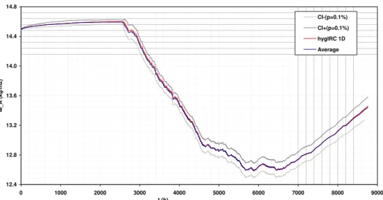
The results of the Benchmark 1 exercise match closely with the results of the other programs in the HAMSTAD project. The hygIRC 1-D results fall within the 0.1% band of acceptance and are consistently close to the averaged results of all the hygrothermal models tested. The results are dependent on the time step chosen. A time step of 0.1 hour (360 s) was found to produce the best results. Time steps shorter than 360 s did improve the results but not significantly. Grid dependency of the solution was not investigated. A comparison of the results is given in the following figures (Figures 13 through 23).
Confidence Limits and Error Analysis
Intervals of confidence with the confidence grade of 99.9% Results for the total moisture content in LB, 1st year
12.4 12.8 13.2 13.6 14.0 14.4 14.8 0 1000 2000 3000 4000 5000 6000 7000 8000 9000 t (h) M_A (kg /m2) CI-(p=0.1%) CI+(p=0.1%) hygIRC 1D Average
Figure 13 hygIRC 1-D Results, 99.9% confidence grade, and averaged results for
total moisture content in load bearing material, 1st year.
Intervals of confidence with the confidence grade of 99.9% Results for the total moisture content in IM, 1st year
0.0 0.1 0.2 0.3 0.4 0.5 0.6 0 1000 2000 3000 4000 5000 6000 7000 8000 9000 t (h) M_A (kg /m2) CI-(p=0.1%) CI+(p=0.1%) hygIRC 1D Average
Intervals of confidence with the confidence grade of 99.9% Results for the total moisture content in IM, 1st year
0.000 0.005 0.010 0.015 0.020 0.025 0.030 8000 8100 8200 8300 8400 8500 8600 8700 8800 t (h) M_A (kg /m2) CI-(p=0.1%) CI+(p=0.1%) hygIRC 1D Average
Figure 15 hygIRC 1-D Results, 99.9% confidence grade, and averaged results for
total moisture content in insulating material, 1st year, 8000 to 8760 hours.
Intervals of confidence with the confidence grade of 99.9% Results for the total moisture content in LB, 2nd year
11.5 12.0 12.5 13.0 13.5 14.0 14.5 8000 9000 10000 11000 12000 13000 14000 15000 16000 17000 18000 t (h) M_A (kg /m2) CI-(p=0.1%) CI+(p=0.1%) hygIRC 1D Average
Figure 16 hygIRC 1-D Results, 99.9% confidence grade, and averaged results for
Intervals of confidence with the confidence grade of 99.9% Results for the total moisture content in IM, 2nd year
0.00 0.01 0.02 0.03 0.04 0.05 8000 9000 10000 11000 12000 13000 14000 15000 16000 17000 18000 t (h) M_A (kg /m2) CI-(p=0.1%) CI+(p=0.1%) hygIRC 1D Average
Figure 17 hygIRC 1-D Results, 99.9% confidence grade, and averaged results for
total moisture content in insulating material, 2nd year.
Intervals of confidence with the confidence grade of 99.9% Results for the total moisture content in LB, 3rd year
11.0 11.5 12.0 12.5 13.0 13.5 14.0 17500 18500 19500 20500 21500 22500 23500 24500 25500 26500 t (h) M_A (kg /m2) CI-(p=0.1%) CI+(p=0.1%) hygIRC 1D Average
Figure 18 hygIRC 1-D Results, 99.9% confidence grade, and averaged results for
Intervals of confidence with the confidence grade of 99.9% Results for the total moisture content in IM, 3rd year
0.00 0.01 0.02 0.03 0.04 0.05 17500 18500 19500 20500 21500 22500 23500 24500 25500 26500 t (h) M_A (kg /m2) CI-(p=0.1%) CI+(p=0.1%) hygIRC 1D Average
Figure 19 hygIRC 1-D Results, 99.9% confidence grade, and averaged results for
total moisture content in insulating material, 3rd year.
Intervals of confidence with the confidence grade of 99.9% Results for the total moisture content in LB, 4th year
10.5 11.0 11.5 12.0 12.5 13.0 13.5 14.0 26100 27100 28100 29100 30100 31100 32100 33100 34100 35100 t (h) M_A (kg /m2) CI-(p=0.1%) CI+(p=0.1%) hygIRC 1D Average
Figure 20 hygIRC 1-D Results, 99.9% confidence grade, and averaged results for
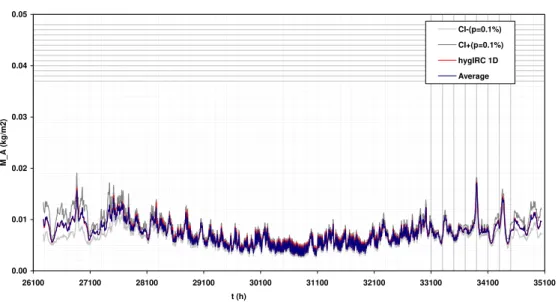
Intervals of confidence with the confidence grade of 99.9% Results for the total moisture content in IM, 4th year
0.00 0.01 0.02 0.03 0.04 0.05 26100 27100 28100 29100 30100 31100 32100 33100 34100 35100 t (h) M_A (kg /m2) CI-(p=0.1%) CI+(p=0.1%) hygIRC 1D Average
Figure 21 hygIRC 1-D Results, 99.9% confidence grade, and averaged results for
total moisture content in insulating material, 4th year.
Intervals of confidence with the confidence grade of 99.9% Results for the total moisture content in LB, 5th year
10.0 10.5 11.0 11.5 12.0 12.5 13.0 13.5 14.0 35000 36000 37000 38000 39000 40000 41000 42000 43000 44000 t (h) M_A (kg /m2) CI-(p=0.1%) CI+(p=0.1%) hygIRC 1D Average
Figure 22 hygIRC 1-D Results, 99.9% confidence grade, and averaged results for
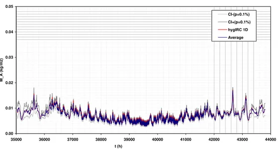
Intervals of confidence with the confidence grade of 99.9% Results for the total moisture content in IM, 5th year
0.00 0.01 0.02 0.03 0.04 0.05 35000 36000 37000 38000 39000 40000 41000 42000 43000 44000 t (h) M_A (kg /m2) CI-(p=0.1%) CI+(p=0.1%) hygIRC 1D Average
Figure 23 hygIRC 1-D Results, 99.9% confidence grade, and averaged results for
total moisture content in insulating material, 5th year.
Benchmark 2 Results
Input
A complete description of the exercise is given in Appendix 2. To run the Benchmark 2 exercise the exterior and interior boundary conditions were fixed. The Benchmark 2 materials package was also loaded using the materials package import feature. The source for the boundary conditions and material properties was the original HAMSTAD document, which is reproduced in Appendix 2.
The Benchmark 2 settings for hygIRC 1-D were:
Case Screen –
Location: Use the default location for hygIRC 1-D
Exterior Screen – See Figure 24 and Figure 25. Time Selection: Years
Time Span: Daily
Input Type: Constant Input Select Years: 1993.
Temperature: 20˚C – constant conditions Relative Humidity: 45% - constant conditions All other variables are set to zero.
Figure 24 Benchmark 2 Exterior Input Screen.
Figure 25 Benchmark 2 Constant Conditions Dialog Box.
Interior Screen – See Figure 26 and Figure 27. Indoor data setting – Click on the button Temperature humidity control dialog box:
Data type: Constant Value Average Period Control: Daily Humidity control: Controlled
Temperature: 20˚C – constant conditions Relative Humidity: 65% - constant conditions
Figure 26 Benchmark 2 Interior Input Screen.
Figure 27 Benchmark 2 Interior Conditions Dialog Box.
Orientation Screen –
Wall Orientation: 0˚ Wall Inclination: 0˚
Structure Screen – See Figure 28. Single-layer structure:
Layer 1: Material A, 200 mm thick, 51 nodes, Equal distance: No, Stretching Factor: 4, Expanding factor: Medium Expanding.
Figure 28 Benchmark 2 Structure Input Screen.
Initial Conditions Screen – See Figure 29. Layer 1: T = 10˚C, RH = 95%
Moisture contents were specified in the benchmark.
Boundary Behaviour Screen – See Figure 30.
Heat Transfer Coefficient: Exterior: 25 W/m2K, Interior: 25 W/m2K
Moisture Transfer Coefficient: Exterior 1.0e-03 s/m, Interior: 1.0e-03 s/m Absorbtivity: 0
Emissivity: 0
Rain Effect: No Rain
Sky Temperature Effect: No Sky temperature Wind Effect: No Wind
Air Diffusion Screen – See Figure 31. Include Stack Effect: No
Include Indoor Ventilation: No Include Wind Ventilation: No
Simulation Parameters Dialog Box – See Figure 32. Start Simulation: 1 Jan. 1993
End Simulation: 28 Feb. 1993 Input Time Step: 3600 sec
Figure 31 Benchmark 2 Air Diffusion Input Screen.
Figure 32 Benchmark 2 Simulation Parameters Dialog Box.
Results
Since it was difficult using hygIRC 1-D to arrange the node locations to correspond exactly to the output locations required by the benchmark the conditions at the required locations were estimated using linear interpolation using nearby node points. A spline fit between adjacent points might produce slightly more accurate results however the correspondence was sufficiently good that this was deemed unnecessary. Shorter time steps did improve the results but not significantly. Grid dependency was not investigated. The results of the Benchmark 2 exercise match closely with the results of the original HAMSTAD work. The hygIRC 1-D results fall within the 0.1% band of acceptance and are consistently close to the averaged results of all the hygrothermal models tested. The correlation coefficient, ρx,y, approached unity when steady state was reached, indicating a
(and standard deviations) of both models are similar. Comparison of the hygIRC 1-D results and the HAMSTAD results are given in the following figures and in Table 2 (Figures 33 through 35).
Confidence Limits and Error Analysis
Table 2 Correlation coefficient, ρx,y, and F-test statistic for hygIRC 1-D and the
original HAMSTAD models at 100, 300, and 1000 hours.
Model
Correlation
Coefficient, ρx,y F-Test
Correlation
Coefficient, ρx,y F-Test
Correlation
Coefficient, ρx,y F-Test
100 hours 100 hours 300 hours 300 hours 1000 hours 1000 hours
KUL 0.999977772 0.991362003 0.999998542 0.994389223 0.999999544 0.990423866 CTH 0.999867256 0.972814105 0.999979458 0.990315328 0.999999405 0.995326958 TUDold 0.999575993 0.968390027 0.999775526 0.977404084 0.999837319 0.995853971 Technion 0.9999965 0.996064242 0.999998259 0.999632786 0.99999995 0.998229126 TNO 0.999996177 0.995436572 0.999999277 0.999671403 0.9999995 0.997564966 TUD 0.999967944 0.990388494 0.999987205 0.994273731 0.999994617 0.995983192 NRC 0.99998553 0.97393356 0.999993158 0.983878959 0.9999951 0.994991861 hygIRC 1-D 0.999864406 0.92633021 0.999963241 0.936474921 0.999903381 0.994381406
Intervals of confidence with th e con fid en ce g rade of 99.9% resu lts fo r th e total w ater conten t 100 hou rs
0.0 10.0 20.0 30.0 40.0 50.0 60.0 70.0 80.0 90.0 0 2 4 6 8 10 12 14 16 18 20 x (cm) w ( k g /m 3 ) CI-(p =0.1%) CI+(p=0.1%) hygIRC 1D Aver ag e
Figure 33 hygIRC 1-D Results, 99.9% confidence grade, and averaged results for water content distribution in the material after 100 hours.
Intervals of confidence with th e con fid en ce g rade of 99.9% resu lts fo r th e total w ater conten t 300 hou rs
0.0 10.0 20.0 30.0 40.0 50.0 60.0 70.0 80.0 90.0 0 2 4 6 8 10 12 14 16 18 20 x (cm) w ( k g /m 3 ) CI-(p =0.1%) CI+(p=0.1%) hygIRC 1D Aver ag e
Figure 34 hygIRC 1-D Results, 99.9% confidence grade, and averaged results for water content distribution in the material after 300 hours.
Intervals of confidence with th e con fid en ce g rade of 99.9% results for the total w ater content 1000 h ours
0.0 10.0 20.0 30.0 40.0 50.0 60.0 70.0 80.0 0 2 4 6 8 10 12 14 16 18 20 x (cm) w ( k g /m 3 ) CI-(p =0.1%) CI+(p=0.1%) hygIRC 1D Aver ag e
Figure 35 hygIRC 1-D Results, 99.9% confidence grade, and averaged results for water content distribution in the material after 1000 hours.
Benchmark 3 Results
Input
A complete description of the exercise is given in Appendix 3. To run the Benchmark 3 exercise the exterior boundary condition file was imported into hygIRC 1-D using the import features. The interior boundary conditions were fixed as per the benchmark. The exterior file was based on the original HAMSTAD boundary conditions and is discussed below. The Benchmark 3 materials package was also loaded using the materials package import feature. The material properties were specified in the benchmark.
The setting up of hygIRC 1-D for the Benchmark 3 exercise requires a longer digression than usual. A point to note is that in reproducing the exercise the boundary conditions
have been kept as they are in the figure provided in the HAMSTAD documentation (see Figure 3 repeated below). In hygIRC 1-D the assumption is that the left-hand boundary is
labelled the exterior boundary while the right-hand boundary is labelled the interior boundary, consequently what is labelled as interior and exterior in the HAMSTAD documentation is reversed in the exercise but the conditions are the same as they
appear in the figure.
The benchmark specifies that a pressure difference of 30 Pa be applied across the sample. Specifically a ΔP of 30 Pa be maintained from t=0 to t=480 h, air flowing from left (hygIRC exterior) to right. After 480 h the pressure is to be gradually reversed i.e. to –30 Pa with the airflow going from right (hygIRC interior) to left from 504 h on.
Figure 3 Description of the boundary conditions for benchmark “Lightweight wall.”
The easiest way to do this would be to specify a time-varying ventilation pressure (interior pressure) according to the schedule above. However it was not possible to schedule the ventilation pressure in hygIRC 1-D v. 1.1. One way of generating the required pressure difference profile was to use 1) the exterior boundary conditions importation feature of hygIRC (i.e. import a weather file) and 2) use the wind speed and wind direction columns in the weather file to generate the required pressure profile. The exterior weather profile comprised the following elements: 1) T = 20°C, 2) RH = 70% 3)
Wind Speed = see below, and 4) Wind direction (˚ from North) see below. All other elements in the weather file were zeroed.
The interior ventilation pressure (right side) was set to zero. Therefore ΔP was assumed to be simply the wind velocity pressure, P. The wind speeds were determined from the following formula relating wind speed and pressure.
air p C P U ρ 2 =
Where: U is the wind speed, m/s
P is the wind velocity pressure, Pa
Cp is the wall averaged pressure coefficient,
ρair is the density of air, assumed to be 1.2 kg/m3.
The formula used in hygIRC 1-D for determining Cp is given below. These pressure
coefficients are wall averaged pressure coefficients. The variation of Cp with the wind
direction is shown in Figure 36 and Figure 37. Cp = (a + c α + e α2)/(1 + b α + d α2)
Where: the coefficients, a, b, c, d, and e are in given below,
α is the angle between the outward wall normal (azimuth), and the wind direction, in degrees.
Table 3 – Coefficients for determining wall average pressure coefficient, Cp.
a 0.591400
b -0.014630
c -0.010930
d 0.000105
Wall Section, Plan
Wind directionAngle, α
Outward wall Normal
NB: for calculating the pressure
Coefficient, Cp, if the angle, α , is greater than 180° than α, Should calculated as 360° - α.
Wall Section, Plan
Wind directionAngle, α
Outward wall Normal
NB: for calculating the pressure
Coefficient, Cp, if the angle, α , is greater than 180° than α, Should calculated as 360° - α.
Figure 36 Method for calculating the wall angle, θ.
Wall averaged pressure coefficients
-0.6 -0.4 -0.2 0 0.2 0.4 0.6 0.8 0 20 40 60 80 100 120 140 160 180 200 Angle Cp Cp
Figure 37 Variation of wind pressure coefficient, Cp, with wind direction,
derived from ASHRAE Handbook of Fundamentals, [2]. The curve is taken from Swami, H. V. and Chandra, S. [3].
Two angles were of interest for purposes of running Benchmark 3, 0º and 180º, assuming that the wall was oriented towards the North (i.e. the outward wall normal was pointing North). The pressure coefficients were, Cp, 0 = 0.5914, and Cp,180 = -0.34428. Once the
wind speed U was calculated, Uref, the value to be included in the “weather file” was
determined. Uref is the wind speed measured at the reference or anemometer height at the
meteorological station. In hygIRC 1-D Href is set at 10m while the building height Hbuilding
is set at 1.8m. Uref was calculated as:
Uref = U/(Hbuilding/Href)0.22 = U /(1.8/10)0.22 = 1.458 U
Using the above procedure two reference wind speeds w1 and w2 (48.27 Km/h from the
North and 63.26 Km/h from the South), were calculated to give the desired wind velocity pressures on the wall and hence the desired ΔP of +/- 30 Pa across the wall. There were two wind speeds because the pressure coefficient was different for wind approaching the wall at an angle of 0º and at an angle of 180º (see Figure 37).
The calculation of the wind speeds during the linear pressure reversal phase was straightforward. The values for each hour were calculated from a linear interpolation between pressure@480h and pressure@504h. Uref was then calculated from the desired
pressure. The wind speeds included in the weather file are summarized in the following table.
Table 4 Table of wind speeds used for Benchmark 3.
Time, h Speed for
input file
Wind Speed, km/h Wind
direction Modeled ΔP Desired ΔP 479 4827.107 48.27106622 0 30 30 480 4827.107 48.27106622 0 30 30 481 4621.603 46.21602732 0 27.5 27.5 482 4406.525 44.06525307 0 25 25 483 4180.397 41.80396962 0 22.5 22.5 484 3941.316 39.41316053 0 20 20 485 3686.764 36.86763581 0 17.5 17.5 486 3413.28 34.13279826 0 15 15 487 3115.884 31.15883926 0 12.5 12.5 488 2786.931 27.86931308 0 10 10 489 2413.553 24.13553311 0 7.5 7.5 490 1970.658 19.70658026 0 5 5 491 1393.466 13.93465654 0 2.5 2.5 492 0 0 0 0 0 493 1826.331 18.26331493 180 -2.5 -2.5 494 2582.823 25.82822766 180 -5 -5 495 3163.299 31.63298937 180 -7.5 -7.5 496 3652.663 36.52662985 180 -10 -10 497 4083.801 40.83801367 180 -12.5 -12.5 498 4473.58 44.73580258 180 -15 -15 499 4832.019 48.32018941 180 -17.5 -17.5 500 5165.646 51.65645532 180 -20 -20 501 5478.994 54.78994478 180 -22.5 -22.5 502 5775.367 57.75367279 180 -25 -25 503 6057.256 60.57256304 180 -27.5 -27.5 504 6326.598 63.26597873 180 -30 -30 505 6326.598 63.26597873 180 -30 -30
The Benchmark 3settings for hygIRC 1-D were:
Case Screen –
Location: Benchmark 3 <or whatever name was used to import the Benchmark 3 weather file>
Exterior Screen – See Figure 38. Time Selection: Years
Time Span: Daily
Input Type: System Input Select Years: 1993.
Figure 38 Benchmark 3 Exterior Input Screen.
Interior Screen – See Figure 39 and Figure 40. Indoor data setting – Click on button Temperature humidity control dialog box: Data type: Constant Value
Average Period Control: Daily Humidity control: Controlled
Temperature: 2˚C – constant conditions Relative Humidity: 80% - constant conditions
Orientation Screen –
Wall Orientation: 0˚ Wall Inclination: 90˚
Structure Screen – See Figure 41. Single-layer structure:
Layer 1: Material BM3, 200 mm thick, 51 nodes, Equal distance: No, Stretching Factor: 7, Expanding factor: Medium Expanding.
Initial Conditions Screen – See Figure 42. Layer 1: T = 20˚C, RH = 95%
Moisture contents were specified in the Benchmark.
Figure 39 Benchmark 3 Interior Input Screen.
Boundary Behaviour Screen – See Figure 43.
Heat Transfer Coefficient: Exterior: 10 W/m2K, Interior: 10 W/m2K
Moisture Transfer Coefficient: Exterior 2.0e-07 s/m, Interior: 7.38e-12 s/m Absorbtivity: 0
Emissivity: 0
Rain Effect: No Rain
Sky Temperature Effect: No Sky temperature Wind Effect: No Wind
Air Diffusion Screen – See Figure 44. Include Stack Effect: No
Include Indoor Ventilation: No Include Wind Ventilation: Yes
Simulation Parameters Dialog Box– See Figure 45. Start Simulation: 1 Jan. 1993
End Simulation: 10 Apr. 1993 Input Time Step: 3600 sec
Figure 42 Benchmark 3 Initial Conditions Input Screen.
Figure 44 Benchmark 3 Air Diffusion Input Screen.
Figure 45 Benchmark 3 Simulation Parameters Dialog Box.
Results
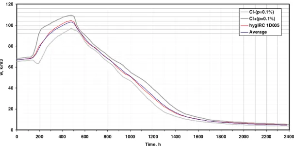
The results of the Benchmark 3 exercise match closely with the results of the other programs in the HAMSTAD project. The hygIRC 1-D results fall within the 0.1% band of acceptance and are consistently close to the averaged results of all the hygrothermal models tested. Shorter time steps did not improve the results nor were the results significantly changed by the use of finer or coarser grids. A comparison of the averaged results with hygIRC 1-D is given in the following figures as well as the confidence bands (Figures 46 through 55).
Confidence Limits and Error Analysis
Intervals of confidence with the confidence grade of 99.9% results for water content at 50 mm
0 20 40 60 80 100 120 0 200 400 600 800 1000 1200 1400 1600 1800 2000 2200 2400 Time, h w, k /m 3 CI-(p=0.1%) CI+(p=0.1%) hygIRC 1D005 Average
Figure 46 hygIRC 1-D Results, 99.9% confidence grade, and averaged results for total water content in Benchmark 3 material, 50mm deep.
Intervals of confidence with the confidence grade of 99.9% results for water content at 100 mm
0 20 40 60 80 100 120 140 0 200 400 600 800 1000 1200 1400 1600 1800 2000 2200 2400 Time, h w, k /m 3 CI-(p=0.1%) CI+(p=0.1%) hygIRC 1D010 Average
Figure 47 hygIRC 1-D Results, 99.9% confidence grade, and averaged results for total water content in Benchmark 3 material, 100mm deep.
Intervals of confidence with the confidence grade of 99.9% results for water content at 150 mm
0 20 40 60 80 100 120 140 0 200 400 600 800 1000 1200 1400 1600 1800 2000 2200 2400 Time, h w, k /m 3 CI-(p=0.1%) CI+(p=0.1%) hygIRC 1D015 Average
Figure 48 hygIRC 1-D Results, 99.9% confidence grade, and averaged results for total water content in Benchmark 3 material, 150mm deep.
Intervals of confidence with the confidence grade of 99.9% results for water content at 170 mm
0 20 40 60 80 100 120 140 0 200 400 600 800 1000 1200 1400 1600 1800 2000 2200 2400 Time, h w, k /m 3 CI-(p=0.1%) CI+(p=0.1%) hygIRC 1D017 Average
Figure 49 hygIRC 1-D Results, 99.9% confidence grade, and averaged results for total water content in Benchmark 3 material, 170mm deep.
Intervals of confidence with the confidence grade of 99.9% results for water content at 190 mm
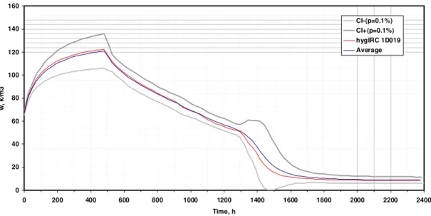
0 20 40 60 80 100 120 140 160 0 200 400 600 800 1000 1200 1400 1600 1800 2000 2200 2400 Time, h w, k /m 3 CI-(p=0.1%) CI+(p=0.1%) hygIRC 1D019 Average
Figure 50 hygIRC 1-D Results, 99.9% confidence grade, and averaged results for total water content in Benchmark 3 material, 190mm deep.
Intervals of confidence with the confidence grade of 99.9% results for temperature at 50 mm 5 7 9 11 13 15 17 19 0 200 400 600 800 1000 1200 1400 1600 1800 2000 2200 2400 Time, h T, C CI-(p=0.1%) CI+(p=0.1%) hygIRC 1D005 Average
Figure 51 hygIRC 1-D Results, 99.9% confidence grade, and averaged results for temperature in Benchmark 3 material, 50mm deep.
Intervals of confidence with the confidence grade of 99.9% results for temperature at 100 mm 2 4 6 8 10 12 14 16 18 20 0 200 400 600 800 1000 1200 1400 1600 1800 2000 2200 2400 Time, h T, C CI-(p=0.1%) CI+(p=0.1%) hygIRC 1D010 Average
Figure 52 hygIRC 1-D Results, 99.9% confidence grade, and averaged results for temperature in Benchmark 3 material, 100mm deep.
Intervals of confidence with the confidence grade of 99.9% results for temperature at 150 mm 0 2 4 6 8 10 12 14 16 18 20 0 200 400 600 800 1000 1200 1400 1600 1800 2000 2200 2400 Time, h T, C CI-(p=0.1%) CI+(p=0.1%) hygIRC 1D015 Average
Figure 53 hygIRC 1-D Results, 99.9% confidence grade, and averaged results for temperature in Benchmark 3 material, 150mm deep.
Intervals of confidence with the confidence grade of 99.9% results for temperature at 170 mm 0 2 4 6 8 10 12 14 16 18 20 0 200 400 600 800 1000 1200 1400 1600 1800 2000 2200 2400 Time, h T, C CI-(p=0.1%) CI+(p=0.1%) hygIRC 1D017 Average
Figure 54 hygIRC 1-D Results, 99.9% confidence grade, and averaged results for temperature in Benchmark 3 material, 170mm deep.
Intervals of confidence with the confidence grade of 99.9% results for temperature at 190 mm 0 2 4 6 8 10 12 14 16 18 20 0 200 400 600 800 1000 1200 1400 1600 1800 2000 2200 2400 Time, h T, C CI-(p=0.1%) CI+(p=0.1%) hygIRC 1D019 Average
Figure 55 hygIRC 1-D Results, 99.9% confidence grade, and averaged results for temperature in Benchmark 3 material, 190mm deep.
Benchmark 4 Results
Input
A complete description of the exercise is given in Appendix 4. To run the Benchmark 4 exercise the exterior and interior boundary conditions files were imported into hygIRC 1-D using the import features. These files were based on the original HAMSTA1-D boundary conditions files. The Benchmark 4 materials package was also loaded using the materials package import feature. The source for the boundary conditions and material properties was the original HAMSTAD document, which is reproduced in Appendix 4.
The setting up of hygIRC 1-D for the Benchmark 4 exercise requires a longer digression than usual. There were two main challenges associated with completing the benchmark exercise, both concerned with the exterior boundary conditions. The boundary conditions are repeated below in Figure 4. The interior boundary conditions were derived from the HAMSTAD specification.
Figure 4. External and internal climatic loads. Heat load from exterior
is given in terms of differences between external equivalent, Teq,e, and
internal, Ta,i, air temperature. Moisture load at external side is given
as a rain flux, and on internal side as the variations in water vapour
partial pressure, pa,i at constant temperature.
Equivalent temperature – The benchmark specifies that both the ambient (air) and
equivalent (surface) temperature be varied according to the exterior boundary conditions specification. The equivalent temperature is the surface temperature at which the heat transfer rate due to the temperature difference across the wall is the same as the rate due to the combined effects of convection, conduction, and radiation (solar and sky). In
hygIRC 1-D it is not possible to specify both the ambient and equivalent temperatures.
The solution was to create a weather file using the equivalent temperatures specified by the benchmark as the ambient temperatures and setting the absorbtivity and emissivity to zero (as was done in all the other benchmark exercises). This however introduced a difficultly in that the benchmark prescribes a constant ambient temperature and a
specified in the benchmark the value of the exterior vapour pressure was held constant with temperature. The relative humidity input for hygIRC 1-D is given in the table below.
Table 5 Relative Humidites corresponding to vapour pressures specified by HAMSTAD.
Temperature, ºC Vapour pressure, Pa RH, %
10 1150 93.6
-2 1150 222.1
50 1150 9.3
The exterior temperature and relative humidity weather profile for hygIRC 1-D is given in Figure 56.
Hamstad BM4 Exterior Temperature and RH Conditions
-25 0 25 50 75 100 125 150 175 200 225 0 20 40 60 80 100 Hours T, ºC; RH, % 120 RH T
Figure 56 Exterior temperature and relative humidity profile.
Moisture Load – Benchmark 4 specifies the direct application of a moisture load to the
exterior surface of the wall. It was not possible to apply a direct moisture load in hygIRC 1-D v.1.1. Using the wind and rain features of the weather file however it was possible to choose the horizontal rainfall, wind speed, and wind direction such that the required moisture load is applied to the wall in the form of wind-driven rain. hygIRC 1-D calculates the wind-driven rain load in the following manner suggested by Straube [5].
WDR = RAF * DRF(rh) cos (θ) V(h) rh l/m2-h
Where: WDR is the amount of wind-driven rain impinging on a vertical surface, l/m2-h
RAF is the rain admittance factor,
rh is the horizontal rainfall intensity mm/m2-h,
V(h) is the wind speed at the height of interest, h V is in m/s, h in meters θ is the angle of the wind direction to the outward wall normal.
DRF(rh) = 1/Vt s/m
Where: DRF is the driving-rain factor, s/m
Vt is the terminal velocity of raindrops, m/s
The terminal velocity can be calculated from the equation given by Dingle and Lee [6]: Vt(Φ) = -0.16603 + 4.91884 * Φ - 0.888016 * Φ2 + 0.054888 * Φ3 <= 9.20 m/s
Where: Vt(Φ) is the terminal velocity of a raindrop of diameter Φ in mm. in still
air (m/s)
The distribution of raindrop sizes for a given horizontal rain intensity is given by Best [7].
F(Φ) = 1 - exp{-(Φ/(1.30 * rh0.232))2.25}, mm
Where: F(Φ) is the cumulative probability distribution of raindrop sizes for rh,
mm,
Φ is the equivalent spherical raindrop diameter, mm,
The predominant drop diameter, Dpred, is the diameter of drops that accounts for the
greatest volume of water in the air. Dpred = a * ((n - 1)/n)1/n, mm
Where: a = 1.30 rhp, p = 0.232, n = 2.25,
The assumed height of the building in hygIRC 1-D is 1.8m. This means that the wind speed in the weather file was corrected for difference between the building height and the assumed measurement height, 10m, in hygIRC 1-D. The correction factor uses a well-known power law formula [6].
Uh = Uref (H/Href)0.22
Where: Uref is the reference wind speed from the weather file, m/s
Uh is the wind speed at the height of the building, m/s,
H is the height of the building, m Href is the measurement height, m. hygIRC 1-D Assumptions
Dpred, is used hygIRC 1-D. A Rain Admittance Factor of 0.4 is used in hygIRC 1-D. The
building height in hygIRC 1-D, H, is 1.8m and the measurement height, Href, is 10m.
Using this information it was possible to calculate a rainfall rate and wind speed to give the desired moisture load on the surface. For this exercise the wind speed, Uref, was
assumed to be constant at 10 m/s coming from the North or 0º. The wall orientation was also towards the North, thus the angle of the wind to the wall normal was 180º. Cosine (θ) was therefore 1. The wind and rain values for the weather are given in the table below. The weather file effect on the exterior boundary heat transfer coefficient was
turned off.
Table 6 Wind and rainfall settings corresponding to the specified HAMSTAD moisture loading HAMSTAD, kg/s Load, l/h Uref, Km/hr Uref, m/sec Uh, m/sec Rainfall, mm/h-m2 calculated WDR, l/h diff, % calculated Load, kg/s 0.0005 1.8 36 10 6.85740739 3.203449 1.8 3.61E-06 0.0005 0.0007 2.52 36 10 6.85740739 4.818289 2.52 2.05E-08 0.0007 0.0008 2.88 36 10 6.85740739 5.660192 2.88 4.58E-06 0.0008
The wind speed and horizontal rainfall rate weather profile is given in Figure 57. The Benchmark 4 settings for hygIRC 1-D were:
Case Screen –
Location: Benchmark 4 <or whatever name was used to import the Benchmark 4 weather file>
Exterior Screen – See Figure 58. Time Selection: Years
Time Span: Daily
Input Type: System Input Select Years: 1989.
Interior Screen – See Figure 59. Pull Down Menu - Imported Data
Hamstad BM4 Exterior Rain and Wind Conditions 0 10 20 30 40 0 20 40 60 80 100 120 Hours
Rainfall, mm/h-m2; Wind Speed, Km/h
WS Rain
Figure 57 Exterior wind speed and horizontal rainfall profile.
Figure 59 Benchmark 4 Interior Input Screen.
Orientation Screen –
Wall Orientation: 0˚ Wall Inclination: 90˚
Structure Screen – See Figure 60. Two-layer structure:
Layer 1: BM4 Load Bearing Material, 100 mm thick, 60 nodes, Equal distance: No, Stretching Factor: 5, Expanding factor: Medium
Expanding.
Layer 2: BM4 Finishing Material, 20 mm thick, 40 nodes, Equal distance: No, Stretching Factor: 3, Expanding factor: Medium Expanding.
Initial Conditions Screen – See Figure 61. All layers: T = 20˚C, RH = 40.99576%
Moisture contents were determined using the suction curve from the Benchmark 4 specification.
Figure 60 Benchmark 4 Structure Input Screen.
Boundary Behaviour Screen – See Figure 62.
Heat Transfer Coefficient: Exterior: 25 W/m2K, Interior: 10 W/m2K
Moisture Transfer Coefficient: Exterior 2.0e-07 s/m, Interior: 7.38e-12 s/m Absorbtivity: 0
Emissivity: 0
Rain Effect: Use weather data
Sky Temperature Effect: No Sky temperature Wind Effect: No Wind
Air Diffusion Screen – See Figure 63. Include Stack Effect: No
Include Indoor Ventilation: No Include Wind Ventilation: No
Simulation Parameters – See Figure 64. Start Simulation: 1 Jan. 1989 End Simulation: 5 Jan. 1989 Input Time Step: 36 sec
Figure 63 Benchmark 4 Air Diffusion Input Screen.
Figure 64 Benchmark 4 Simulation Parameters Dialog Box.
Results
The results of the Benchmark 4 exercise match closely with the results of the other programs in the HAMSTAD project. The hygIRC 1-D results fall within the 0.1% band of acceptance and are consistently close to the averaged results of all the hygrothermal models tested. The benchmark results seem to be strongly dependent on the time step chosen. Shorter time steps did improve the results. A time step of 0.01 h (36 s) seem to best fit the HAMSTAD data. Grid dependency was not investigated. Note that for this benchmark the band of acceptance was only calculated for the surface temperatures and moisture contents. This was because the models used in the HAMSTAD project all used different grids. A common set of reporting coordinates was not used to report the results as was done in Benchmark 2. Consequently for points within the materials a comparison with hygIRC 1-D and the other models is presented in Figures 65 through 78. The bands of acceptance are reported in Figures 79 to 82.
MOISTURE CONTENT ON OUTER SURFACE 0 50 100 150 200 0 24 48 72 96 120 time (hours) moisture content (kg/m³) NRC Results hygIRC 1D results Chalmers IBP TECHNION TUD KUL
Figure 65 Time history of the moisture content, Kg/m3, on the exterior surface for all
models tested in Benchmark 4.
MOISTURE CONTENT ON INNER SURFACE
0 50 100 150 200 0 24 48 72 96 120 time (hours) moisture content (kg/m³) NRC Results hygIRC 1D results Chalmers IBP TECHNION TUD KUL
Figure 66 Time history of the moisture content, Kg/m3, on the interior surface for all models tested in Benchmark 4.