Publisher’s version / Version de l'éditeur:
Vous avez des questions? Nous pouvons vous aider. Pour communiquer directement avec un auteur, consultez la première page de la revue dans laquelle son article a été publié afin de trouver ses coordonnées. Si vous n’arrivez pas à les repérer, communiquez avec nous à [email protected].
Questions? Contact the NRC Publications Archive team at
[email protected]. If you wish to email the authors directly, please see the first page of the publication for their contact information.
https://publications-cnrc.canada.ca/fra/droits
L’accès à ce site Web et l’utilisation de son contenu sont assujettis aux conditions présentées dans le site LISEZ CES CONDITIONS ATTENTIVEMENT AVANT D’UTILISER CE SITE WEB.
Paper (National Research Council of Canada. Division of Building Research); no.
DBR-P-707, 1976-11
READ THESE TERMS AND CONDITIONS CAREFULLY BEFORE USING THIS WEBSITE. https://nrc-publications.canada.ca/eng/copyright
NRC Publications Archive Record / Notice des Archives des publications du CNRC : https://nrc-publications.canada.ca/eng/view/object/?id=b2abb5d3-2a62-4a93-85fe-38e8f9cddbbe https://publications-cnrc.canada.ca/fra/voir/objet/?id=b2abb5d3-2a62-4a93-85fe-38e8f9cddbbe
NRC Publications Archive
Archives des publications du CNRC
This publication could be one of several versions: author’s original, accepted manuscript or the publisher’s version. / La version de cette publication peut être l’une des suivantes : la version prépublication de l’auteur, la version acceptée du manuscrit ou la version de l’éditeur.
For the publisher’s version, please access the DOI link below./ Pour consulter la version de l’éditeur, utilisez le lien DOI ci-dessous.
https://doi.org/10.4224/40001762
Access and use of this website and the material on it are subject to the Terms and Conditions set forth at
Fire resistance versus flame spread resistance
I
Ser TH1N21d no.
707
NATIONAL RESEARCH COUNCIL OF CANADA
CONSEIL NATIONAL DE RECHERCHES D U CANADA
SOMMAIRE
L'auteur examine la conception conventionnelle de la rQ- sistance au feu et introduit une conception plus neuve. I1 dQcrit une mQthode qui permet d'obtenir une Qvaluation rhaliste du fonctionnement de certains QlQmenta-cl& de construction dam un Qdifice.
FIRE TECHNOLOGY Vol. 12 No. 4 November 1976
Fire Resistance v&rsus
Flame Spread Resistance
T.2.
HARMATHYDivision of Building Research
National Research Council of Canada
Current fire resistance tests of compartment boundary materials should be referred to as "fire spread resistance" tests. Unless additional fire protection measures have been taken, compartment boundaries are rarely able to prevent the spread of fire out of the space of origin. The true fire resistance of all key building com- pqnents, therefore, must be judged on ability of those components to withstand fire exposure from two sides.
M
ANY FIRE experta still regard fire resistant compartmentation as the basic measure of fire protection. I n the absence of other pro- tecting measures, fire can spread through well-compartmented, fire re- sistant buildings alm& as easily as in other buildings. Even the experts realizing this believe that the fire resistant quality of certain structural elements of the building is an essential part of the overall fire protection system.In this paper, the conventional concept of fire resistance will be ex- amined and a newer concept introduced. A procedure will be described by which a realistic appraisal of the performance of some key structural corn- ponente of a building can be obtained.
F I R E R E S I S T A N C E T E S T S
In North America, ASTM Method E-119 (similar to Standard Methods of Tests of Building Construction and Material, NFPA No. 251) speczes the conduct of fire resistance tab and the interpretation of the findings. During a fire resistance tat, a representative sample of an element of compartment boundary (structure) is exposed on one side to the fire of a h t furnace whose temperature is programmed to follow a unique curve, steadily increasing with time. This curve is assumed to reproduce the --
NOTE: Dr. Harmathy is a research officer in the Fire Research Section, Division of Building Research, National Research Council of Canada, Ottawa.
Copvrlrhl O 1 9 7 6 , NATIONAL FIRE PROTECTION ASSOCIATION, 4 7 0 ATLANTIC AVE., BOSTON. MASS. 02210 Printed In U.S.A.
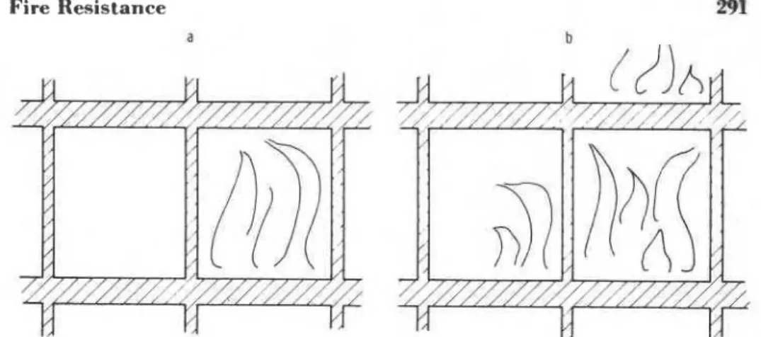
Fire Resistance a
Figure I . ( a ) Fire exposure as implied by test standards. Compartment boundaries are ex- posed to fire on one side only. (b) Realistic fire exposure. Some compartment boundaries are exposed to fire on both sides.
temperature history of a hypothetical, fully developed* compartment fire. The test usually is continued until the specimen fails. Three types of failure are specified by the test standard: (1) the attainment of a critical temperature (about 325" F or 163" C) by the surface of the specimen opposite to the fire exposure; (2) the attainment of a critical temperature by some load-bearing steel component in the construction (800, 1000, or 1100" F or 427, 538, or 593" C); and (3) collapse of, or serious damage to, the specimen.
The desired duration of exposure of the compartment element to the
test
fire is the minimum period for which fire resistance rating (expressed in hours and fractions and multiples thereof) is required by an authoritative building code. If the specimen construction withstands the simulated fire exposure for 1M
hr without failure, the compartment element that it repre- sents is "rated" as 1 % hr fire resistant construction. A compartment built entirely from elements with fire resistance ratings not less than the mini- mum required by the building code for the type of building is referred t o as a fire resistant compartment. Requirements usually range fromN lo
3.
hr.Hccause the specimens are exposed to the test fire on one side only, the rteulls of fire resistance lests are applicable only to fires confined to a uitlfili* cbomparlment (Figure la). Indeed, the philosophy of fire resistance lest itlg was lwill on the belief that fire resistant compartment boundaries arc csnpnhle of preventing the spread of fire. Judging from the criteria of f'tlilurt. in the fire test, one can conclude that the confinement of the fire lo t~ sitlgle compartment is believed to be satisfactorily achieved if the c'ompt~rlment boundaries are (a) sufficiently resistant to heat transmkion 1 o prevent the development of dangerously high temperatures in an ad- "l'hta ptariod o f "fully developed" fire is the vigorously burning period d u r i r r ~ which 80 t o 85 percrrit o f the combustible materials originally present in the compartment are c~~ll*ulllrd.
292 Fire Technology
jacent (horizontally or vertically) building space and (b) strong enough to withstand structural failure and, thereby, the dispersion of flames.
Asmming, for the time being, that there
is
no flaw in the philmophyof
h
resistance h t i n g , one can eee that these teek were visualized to yield information on the ability of c o m p h e n t boundaries to withstand the s p m d of 6 . r ~ in building and that, correctly, one should refer tothem
as "fire spread mistance" testa.The
practice of using the test d Bto judge the performance of various shctural elements in r&tic ks,
aa
characterized by some degree offire
spread beyond the place of origin,* is of somewhat dubious value,as
will be shown.F I R E D U R A T I O N
Once it
has
become established that the true meaning of the reeult of a fireteat
is a sort of fire spread resistance of an element of compartment boundary, it becomes imperative to examine what fire spread resistance re- quirements one can regard as realistic. If the fire spread resistant bound- aries areas
effective as implied by the philosophy of fire testing, the maxi- mum requirement need not be much higher than the time required for the complete burnout of a compartment without human intervention.Based
on hundreds of compartment burnouttesta
performed in severalcountria and on valuable earlier theoretical work by others, this author gave a comprehensive analysis of the characteristics of compartment fires.' The following equations, describing the duration of fully developed com- p a r b e n t fires, are somewhat simplified forms of equations presented therein.
t
$If C
<
0.079 7 = 0.0249/C (1)where
C
is an extremely important parameter of fully developed fires.It
will be refmed to hereas
the "control parameter." Equation 1 relates to poorly ventilated "ventilation-controlled" fires, and Equation 2, to well-ventilatedB the uee of aome engineering techniques, e.g., sprinklering, various methods of tln h o i t i o n and fire drainaqe, it i~ possible to eliminate or substantially reduce the porwribility of Are epread. I t 1s amumed in this paper t h a t such engineering techniques are not employed.
tThe meaning of the eymbole are explained in Appendix B.
$It
in
miatornary to Baeurne that, after a window has been broken by t h e fire, t h e total w~ndow arm iu available for the inflaw of air, ementially throughout the entue eriod of fully developed fire. There have been suggestione, however, t h a t eome groken pieces of the ane may atay in place for anme time and hinder airflow. TO take account of this poasi!ility, the designer may choose the "effective" window area, A r , M somewhat smaller than the total window area or, alternatively, specify window t h a t eutomatiunlly awing open on expoaure t o fire.Fire Resistance 293 TABLE 1. Duration of Fully Developed Comportment Fires
T min
"fuel-surface-controlled" fires. These equations have been used to calculate the values presented in Table 1.
To admit sufficient light, the total window area is usually selected to amount to a t least 10 percent of the floor area.* Thus only the values in the clear area of the table are of practical significance for modern buildings. Those in the shaded area are for buildings having window areas less than 10 percent of the floor area. Since, in residential and office buildings, the average specific fire load is known to amount to about 4.5 lbs/ft2
(22 kg/m2)
,*
- the data in Table 1 clearly indicate that, unless the fieload is unusually high, a fully developed compartment fire is not expected to last longer than 30 min. In fact, fires longer than 1 hr should usually be regarded as clear indications that the fire spread resistant boundaries did not fulfill their function. I t appears certain, therefore, that wall
and floor fire spread resistance requirements well over 1 hr are often not
fully justifiable. Only for poorly ventilated spaces (e. g., basements,
I.lleaters, and large halls) or for spaces that are liable to accumulate higher tllntl average fire loads would a fire spread resistance in excess of 1 hr be appropriate.
'I'lle finding that fire can, and often does, spread to other building H~R(-C'S it1 spite of fire spread resistant compartment boundaries, cornea as
uo mtrprke to fire experts. It is we11 known that fire rarely spread8 hy
tlstuwrive heat conduction or structural damage, as is assumed hy the fir[:
t cwt philtlaophy. hiost often it spreads horizontally through (Jorjrw that wc:rr: ItVt't optSn. vertir-aHy through windows that were broken hy fire, and t)ot,h l~orixou tally and vert i d y through improperly fire-stopped or protectetl opt~tlings.
*A Ilritish survey2 of modern office buildings indicated that, if the building is well c(b~tr~~r~rtnletlted, the average value of the ratio of (actual) window area to floor area is l~igllur than 0.3.
!294 Fire Technology
T W O - S I D E D F I R E E X P O S U R E
The weaknesses of the principle of fire resistant compartmentation are clearly recognized by now. Yet, many fire experts still favor the use of highly fire spread resistant compartment boundaries, but for a reason entirely incompatible with the philosophy of conventional fire testing - to protect the structural integrity of the most vulnerable components of the building following the spread of fire.
Once the fire has spread to the neighboring compartment, the threatened compartment boundary becomes exposed to fire from two sides (Figure lb) -
a
condition that is not covered in the standard fire test procedure. The problem is further complicated by the fact that fire exposure of the two sides is not necessarily simultaneous, and that delayed fire in a neigh- boring compartment may cause more serious structural problems than a simultaneous fire.If it were possible to devise a single fire test that could clearly reveal the most adverse structural performance of building components in realistic (spreading) fires, that test could be rightfully referred to as a fire resistance test. Although such a test may never be practical, the designer must not be overly concerned. Thanks to substantial improvement in recent years in the understanding of material behavior a t elevated temperatures and to the use of computers in heat flow analyses, the analytical appraisal of the behavior of building components in fire has become, in many cases, a distinct alternative to fire testing. Admittedly, there are still some dif- ficulties in the stress-strain analysis of fire-exposed structures, yet these can often be circumvented by prudent design, or resolved by small-scale benchtop type testing.
In the following section, the kinds of calculations needed for the assess- ment of the performance of some key building components in fires will be described and illustrated.
H E A T F L O W A N A L Y S E S
One can usually assume that the conditions in the two (horizontally or vertically) adjacent compartments (Compartments 1 and 2) on either side of the building element to be analyzed are similar, so that the char- acteristics of fire, among them the duration of fully developed fire, are roughly identical. Under these circumstances, it is convenient to introduce a "delay factor" interpreted as
and carry out analyses for a number of values* of J.. J. = 0 indicates fire beginning a t the same time in both compartments, J. = 1 indicates that in Compartment 2 the fully developed period of the fire begins when it ends in
'It will be seen later that, with some insight into the roblem, these analyses can be completely dinpensed with, or their number substantiaiy reduced.
Fire Resistance 295 TABLE 2. Information Used in the Numerical Studies
A) Concrete slab
thickness: 1 = 0.5 ft
density: p = 137 lb/fta
thermal conductivity: k = 0.971 Btu/hr ft " F specific heat: c = 0.310 Btu/lb " F B) Coefficients of heat transfer
before fully developed fire: hb = 2.0 Btu/hr ft2 " F during decay period: hd = 4.5 Btu/hr ft2 O F
C) Factors affecting fire characteristics and fire severity parameters Fire severity parameters
F Nw - Aw C r Q E
Fire (lb/ft2) (ft) AF (ftb12/lb) ,in T, (" F) (Btu/hr ft2)
H 6.15 6.0 0.196 0.0781 19 1600 9380
(24) (1575)
D) Delay factors chosen
for Fire H: $ = 0, 1, 2, m for Fire V:
+
= 0, 0.5, 1, mCompartment 1, and # + m indicates an isolated fire in Compartment 1,
developing in a way similar to that assumed by the conventional fire testing philosophy.
The building element to be studied has been selected as a simple one deliberately - a 6-in-thick reinforced concrete slab that may be regarded
as part of a load-bearing wall or ceiling separating Compartments 1 and 2 (assumed to be identical). All information pertinent to the study is listed in Table 2.
As will be shown in Appendix A, the temperature history of the slab (or any building element in fire) depends primarily on two variables; T and qc. In Table 2 they are referred to as "fire severity parameters."
The severity of fires is characterized by a group of three parameters - the duration of fully developed fire, 7 ; the average gas temperature in the
compartment during the period of fully developed fire,
T,; and the "effec-
live heat. flux," i.e., the average heat flux penetrating the compartment boundaries, qa, during the period of fully developed fire. The value of Tcbt11i I)ta c*alculated from Equations 1 to 3. Those of
T ,
andqs
are obtainedfrom the trial anti error solution of two equations (Equations 51 and 62 of I2cftbrenc.e 1 ) . The values in the brackets in Table 2 relate to experimental val11t.s derived from the test results of Butcher et al.
"
rl'l~e lwhavior of the slab will be analyzed under two sets of fire con- ditions. They represent simulations of two full-scale burnout testa from anloug a staries conducted by Butcher et al." The first fire, referred to m Fire H. is c~haracterized by a control parameter, C, very close to the critical value. 0.079 (see Equations 1 to 3). To empfiasize the significance of this
296 Fire Technology fact, attention is directed to the full-lined curves in Figure 7 of Reference 1,
which represent plots (at three specific fire loads) of the effective heat flux against the "ventilation parameter," a variable of which the control parameter, C, used in this paper, is a normalized form. (The critical values of the ventilation parameter, indicated by mows in the figure, correspond to the critical value of the control parameter, 0.079.) Since the maxima of
q~ are seen to occur always a t C = 0.079, and the values of these maxima depend hardly a t all on the specific fire load, and since decreases sharply
as C increases beyond 0.079 while T remains unchanged (see Equation 2), one can conclude that Fire H represents the most adverse conditions (or nearly so) that may occur among well-ventilated, fuel-surface-controlled fires, i.e., whenever C
>
0.079.The second fire, referred to as Fire V in Table 2, represents a very severe fire, due to the high specific fire load and poor ventilation (and the resulting low value of the control parameter). The great severity of this fire, in relation to Fire H, is manifest from its long duration, which grossly overshadows the somewhat lower value of the effective heat flux.
The first step in evaluating the fire resistance of a construction is the calculation of its temperature history under the most adverse fire conditions that may arise. Because the fire severity parameters are determined by the design and contents (and, in turn, by the occupancy) of the building, finding the most adverse temperature history consists (in principle) of a series of heat flow studies performed for a range of values of the delay factor, $, a t constant values of the fire severity parameters. The numerical procedure used in the studies of this paper is given in Appendix A.
The calculation procedure is different from the conventional ones. I t has been customary to use a temperature history for the compartment (e.g., the temperature-time curve defined by ASTM E-119 when dealing with standard fire exposure) as the imposed reference condition. In this paper, the effective heat flux (i.e., the average heat flux penetrating the con- struction) is used as the imposed reference condition during the period of fully developed fire. In this way not only do the calculations become more simple (a constant rather than a variable quantity is used in the boundary conditions), but the results become more realistic.
*
The surfaces of the con- etruclion are assumed to exchange heat with the surroundings according to Newton's law before and after the period of fully developed fire.To avoid unnecessary complications, the material properties and heat Lransfer coefficients have been selected as constants. Because of the neglect of the beneficial effect of moisture, the calculation errors are on the safe side.
*The control parameter unicluely determines the rate of burning of the combustible matvrials in the compartment and, in turn, the rate of heat evolution (see Reference 1 for details). The effective heat flux can be calculated as described in Reference 1, or just entimated for weliminary calculations as 10 to 50 percent of the rate of heat ev(,luth)n from the rue,. (Higher percentage values usually pertain to lower values of the control parameter).
Fire Resistance 297
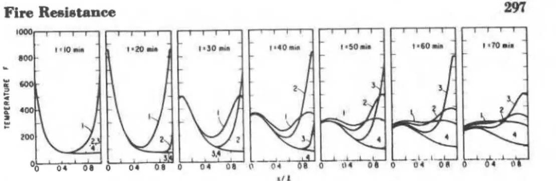
Figure 2. Temper- history of 6-in. r e i n f o d concrete slab under exposure to Fire H.
Curves: (I) $ = 0, (2) $ = 1, (3) $ = 2, ( 4 ) $+ ao.
Some reaulta of the two seriea of heat flow analyses are presented in Figurea 2 and 3. The temperature histories of the two steel reinforcing bars, assumed to be located a t 1 13/64 in. from the surfaces, are shown in Figures 4 and 5.
E V A L U A T I O N O F T H E F U L L R E S I S T A N C E T O S P R E A D I N G F I R E
Once the reaulte of heat flow analysis are available, the designer can decide whether the construction is liable to undergo thermal conditions that may endanger its stability. Unfortunately, there is no well-defined procedure that he can follow. In the case of construction containing con- crete and steel, his decision may be based on the following facts: (1) the
logs of ultimate and yield strengths of structural and reinforcing steels is usually i n s i i c a n t below 700"
F
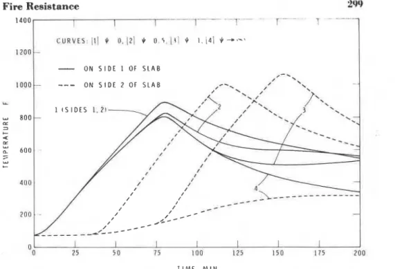
(371" C),7 (2) the creep of steel be- comes substantial above 1,000" F (538" C),' (3) the loss of compressive strength of most concretes is negligible up to about 400" F (204" C)," and (4) concretes of low permeability may spall in fire a t relatively low moisture content.1°If concrete is regarded only as an insulating cover on the load-bearing steel bars, the temperatures that it may attain need not be considered. The only important consideration is that it must not be liable to spall or disintegrate under the prevailing conditions. On the other hand, if the concrete carriee a subtantial compressive load, that portion of the con- Figure 3. Temperature history of 6-in. reinfomed conrrete slab under exposure to Fire V .
298 Fire Technology 700 I I I I I I I
1
,OO1
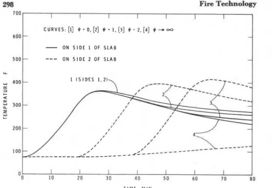
C U R V E S : [I] $'= 0. [2] $-
1. [3] $ = 2, [4] 9 - 0 0-
ON S I D E 1 OF S L A B---
O N S I D E 2 OF S L A B Y 1 ( S I D E S 1.21 4 o o tA--:
TIME. M I NFigure 4. Temperature of Bteel reinforcing bars in Fire H. Bars located at a depth of 1 ' ' ~
in. f m m surfaces.
mete attaining temperaturea in excess of 400"
F (371"
C) may exhibit significant plastic deformation and become the cause of an undesirable redistribution of streams.An inspection of Figure 4 reveals that, in Fire H, the steel reinforcing bars did not attain a temperature that could be considered as d e h e n t a l for any of the delay factors examined. If the construction is strongly re- strained, the designer may have to consider the streas build-up caused by the thermal expansion of steel and concrete. Experience obtained from standard fire
tests
indicates that, if the construction is exposed to fire from one side only, it can absorb much of the excess stress without serious damage by deflecting toward the fire. Unfortunately, experimental information is not readily available on the more adverse situation when a construction is exposed to fire on both sides simultaneously.A cloee examination of Figure 2 will reveal that, as the delay parameter incrsaeeg (within a range that may have practical significance), the thick- ness of the layer on Side 2 ( x / l = 1) of the slab that attains a temperature of 400"
F
or more will increase slightly. Consequently, some problems mayarise if the concrete slab is loaded with a bending moment (e.g., if it is
part of a ceiling) and if, as is usual, the compressive strength of concrete hae been relied on in the design. Yet, as emphasized earlier, Fire H may be considered as representing the most adverse conditions among fuel-surface- controlled fires. In view of this and of the fact that the maximum tempera-
Fire Resistance 2w 1400 ,l . -. . .
,
.,
--,
I-
O N S I D E 1 OF S L A B T I M E , M l NFigure 5. Temperature of steel reinforcing bars in Fire V . Bars located at a depth of 1la4
in. from surfaces.
lower had the beneficial effect of moisture been considered, one may venture to say that the designer need not be overly concerned with the structural performance in fire of conventionally designed reinforced con- crete constructions in residential or office occupancies as long as the control parameter is larger than 0.079 - in other words, as long as the potential fires are expected to be fuel-surface-controlled. This claim is essentially a confirmation of the one made earlier by this author" on the basis of less comprehensive reasoning.
As Table 1 shows, the value of the control parameter for Fire V is much less than the critical value, 0.079. This fire is strongly ventilation-controlled and, therefore, very severe. Figures 3 and 5 reveal that, in the case of two- sided exposure, the temperature of the entire concrete mass may rise above the critical 400" F (204" C) limit and, with substantially delayed exposure of Side 2 (xi1 = I ) , the temperature of the steel reinforcing bars on that side may also rise well into the region of fast creep. To avoid possible structural failure, the designer can either change the construction (e.g., by applying insulation to both sides of the slab) or make some changes in
the cbompartment design (e.g., increase window area or window height or both, or reduce the fire load) in order to increase the control parameter t.o above 0.079.
Even if the key structural element is part of the outside shell of a building, it may still be exposed to fire on both sides. The exposure of the outer surface originates from the flames issuing from the windows. The
Fire Technology
duration of the outside exposure is roughly equal to the period of fully developed fire in the adjoining compartments. Heat flux to the outer sur- face may be estimated from the energy released by the fuel outside the windows, as described in Reference 1.
C O N C L U S I O N S
What is usually referred to as the "fire resistance" of compartment boundaries is, in effect, a measure of their ability to prevent the spread of fire by some mechanisms implied by the standard test procedure. In reality, fires spread by different mechanisms and, therefore, compartment boundaries may become exposed to fire on both sides. The results of standard fire teats are not applicable to such situations.
The performance of a simple but common structural element of a build- ing has been analyzed under conditions corresponding to two realistic fires. I t has been concluded that conventional concrete-steel structures are likely to function satisfactorily in a spreading fire, provided that the "control parameter" characterizing the nature of the fire is higher than a critical value.
R E F E R E N C E S
Harmathy, T. Z., "A New Look a t Compartment Fires - Parts I and 11," Fire
Technolo y, Vol. 8 (1972), pp. 196 and 326.
~alcfwin, R., Law, M., Allen G., and Griffiths, L. G., "Survey of Fire Loads in Modern Office Buildings - Some Preliminary Results," JFRO, Fire Research Note No.
AOR (1 Q7n\
- - - -
- .-
,.
"itteveen, J., "Brandveilighed Staalconstructies," Centrum Bouwen in Staal, Rotterdam, Holland (1966).
'
Nilmon, L., "Brandbelastning i Bostadslangenheter" (Fire Loads in Flats), Report No. 34:1970 of the National Swedish Inetitute for Building Research.Butcher, E. G., Chitt , T. B., and Ashton. L. A., "The Tem eratures Attained by Steel in Ruilding Fires," ~ R Fire Research Technical Paper &o. 115 (1966). O
'Butcher. E. G.. Bedford, G. K., and Fft;rdell, P. J., "Further Experiments on 'I'ernperatures Reached by Steel in Buildings, P a er 1, Proceedings of a Symposium held a t the Fire Research Station, January 1967, &RO (1968), p. 1.
A P P E N D I X A
Because the mass of steel in a conventional reinforced concrete structure is negligible in comparison with the mass of concrete, the presence of the reinforcing bars can be disregarded in heat flow studies. Thus, the heat flow through a reinforced concrete slab can be modeled as that through a homogeneous concrete slab.
Fire Resistance 301 Figure 6 shows the subdivision of the slab into a number of elementary slabs in preparation for the numerical heat flow analysis. The reference points in the elementary slabs are numbered from 0 to N. The numerical procedure is similar to that described in Reference A-1 and will not be discussed here in detail. The equations used for the calculation of the temperatures a t the reference points and a t time level t = ( j
+
1) At are t~follows: for point 0; for points 1
5
n5
N - 1; for point N; where, if tol = 0, 91' =1%
hd(Ta
-
To')
if
t>
7The reason for including the coefficient 2/3 in Equations A5 and A8 is as follows. After the period of fully developed fire, fresh air continues to rush into the compartment a t approximately an unchanged rate, so that the temperature in the compartment decreases rapidly. Yet the charring remains of the fuel continue to evolve heat a t a rate amounting to about 13 percent of that during the fully developed fire. I t is estimated that a realistic "driving force" for the cooling of the construction during this so-called "decay period" of fire is obtained if the driving force toward a cool environment is reduced by one third.
The initial conditions are, if t = 0,
These computations were performed with the aid of an HP9820A program- mable desk calculator.
302 Fire Technology
R E F E R E N C E
Harmathy, T. Z., A Treatise on Theoretical Fire Endurance Rating, ASTM Special Technical Publication No. 301 (American Society for Testing and Materials, Philadelphia. 1962), p. 10.
A P P E N D I X B - N O M E N C L A T U R E
A = area, "effective" area (for windows), ft2
c = specific heat, Btu/lb
"
F
C = control parameter, ft5/2/lb
F
= specific fire load, lb/ft2h = heat transfer coefficient, Btu/hr ft2
"
F
H = height, ft
k
= thermal conductivity, Btu/hr f t"
F
I
= thickness of slab, ftn = 1 , 2 ,
.
. .
N-1N = number of reference points less one
q
= heat flux, Btu/hr ft2qe = "effective heat flux," Btu/hr ft2
t = time, hr (min in Figurea 2 to 5 for convenience)
At = time increment, hr
T = temperature, O F
-
T,
= average gas temperature in compartment, OF
x = distance from side 1 of slab, ft
Ax = distance between reference points
GREEK LETTERS P = density, lb/fv
T = duration of fully developed fire, hr (min in Tablea 1 and 2 and
Figures 2 to 5 for convenience) = delay factor, dimensionless
,,
= pertaining to the time preceding the period of fully developed fire,I = pertaining to the "decay period" of fire
..
= of the cool environmentP = of the floor
, = at, the n-th reference point
N = a t the N-th reference point
,, = of the beginning of period of fully developed fire; a t the 0-th refer- ence point; a t t = 0
w = of the window
1 = (when used with t or q) for the fire in compartment 1, or for side 1
of the slab (at x/l = 0)
s = (when used with t or q) for the fire in compartment 2, or for side 2 of the slab (at x/l = 1)