HAL Id: hal-00470023
https://hal.archives-ouvertes.fr/hal-00470023
Submitted on 19 Aug 2010
HAL is a multi-disciplinary open access
archive for the deposit and dissemination of
sci-entific research documents, whether they are
pub-lished or not. The documents may come from
teaching and research institutions in France or
abroad, or from public or private research centers.
L’archive ouverte pluridisciplinaire HAL, est
destinée au dépôt et à la diffusion de documents
scientifiques de niveau recherche, publiés ou non,
émanant des établissements d’enseignement et de
recherche français ou étrangers, des laboratoires
publics ou privés.
Ligth by light polarization control for
telecommunication applications
Julien Fatome, Stéphane Pitois, Philippe Morin, Christophe Finot, Guy Millot
To cite this version:
Julien Fatome, Stéphane Pitois, Philippe Morin, Christophe Finot, Guy Millot. Ligth by light
po-larization control for telecommunication applications. 12th International Conference on Transparent
Optical Network, Jun 2010, Munich, Germany. pp.Mo.B1.3. �hal-00470023�
Light-by-light polarization control
for telecommunication applications
Julien Fatome, Stéphane Pitois, Philippe Morin, Christophe Finot and Guy Millot
Laboratoire Interdisciplinaire Carnot de Bourgogne, UMR 5209 CNRS/Université de Bourgogne, 9 Av. Alain Savary, 21078 Dijon, France
e-mail: Julien.Fatome@u-bourgogne.fr
ABSTRACT
In this work, we report for the first time the experimental achievement of an all-fibered polarization attraction, which can occur in optical fibers at telecommunication wavelengths. More precisely, we have experimentally shown that is possible to all-optically control and stabilize the state of polarization of a 10 Gbit/s telecommunication signal through the injection of a counter-propagating control pump wave. Eye diagrams recordings and bit error rate measurements have shown that this new type of all-optical function, almost lossless and instantaneous has a promising potential for telecommunication applications.
Keywords: Optical fiber, Nonlinear effect, Polarization control, all-optical signal processing.
1.INTRODUCTION
In many photonics applications, especially in optical fiber based systems, the state of polarization of light remains so far an elusive uncontrolled variable, which can dramatically affect the performances of telecommunication systems and which one would like to control as finely as possible. Indeed, polarization sensitivity of a large number of systems, such as Nonlinear Optical Loop Mirror (NOLM) [1], coherent detection
[2] or optical-fiber based transmission links and associated polarization mode dispersion impairments [3]- [4], is
a major drawback for both their implantation and long-time stability. In this context, any device which can repolarize or stabilize an arbitrarily polarized optical signal by means of a lossless and instantaneous interaction should be considered with a great interest. A typical and remarkable example of such a system is the photorefractive crystal-based nonlinear polarizer reported by Heebner et al. in ref. [5] or Raman and Brillouin pulling effect [6]- [9]. In a more recent work, we have identified another type of polarizing process taking place within an optical fiber pumped by two counter-propagating beams and based on a four-wave mixing approach
[10]. More precisely, it has been shown that a circularly polarized pump could act as a lossless polarization
attractor for a signal beam propagating in the opposite direction [10]- [11]. In this paper, we exploit this phenomenon to experimentally demonstrate that it is possible to all-optically control and stabilize the state of polarization of a 10-Gbit/s Telecommunication signal.
2.EXPERIMENTAL SETUP
Figure 1 illustrates the experimental setup. The polarization attractor consists of a 20-km long Non-Zero Dispersion-Shifted Fiber (NZ-DSF, D=1.8 ps/km.nm at 1550 nm) characterized by a low polarization mode dispersion (PMD) of 0.03 ps/km1/2. This weak value of PMD allows us to model the fiber as a concatenation of several ideal attractors such as described in ref. [10]. The key advantage of such a configuration is that, compared to preliminary results obtained in nanosecond regime [11], increasing the nonlinear interaction length by three orders of magnitude enables to significantly decrease the average powers required to observe the attraction process. Moreover, because of the residual PMD of the fiber and its associated polarization random walk along the fiber length, the attraction phenomenon is no longer restricted to circular polarizations.
The fiber is then coupled to two optical circulators so as to inject and monitor the two counter-propagating waves. The initial signal is made of an optical 231-1 return–to-zero pseudo random bit sequence (PRBS) cadenced at 10 Gbit/s with 30-ps pulses and a wavelength of 1548 nm. A polarization scrambler was also inserted in order to introduce random polarization fluctuations. Finally, before injection into the optical fiber, an Erbium doped fiber amplifier (EDFA) was used to reach the suitable average power of 300 mW. The counter-propagating pump beam, defined to control and stabilize the output polarization state of the signal, consists of a linearly polarized incoherent wave with a spectral bandwidth of 30-GHz centered around 1545 nm and an average power of 600 mW. At the system output, the signal polarization state was analyzed on the Poincaré sphere by means of a commercially available polarization analyzer. Finally, a 30-GHz bandwidth oscilloscope associated with a bit error rate (BER) analyzer allowed to monitor in real-time the intensity profile of the outcoming pulses and signal quality.
Figure 1. Experimental setup. Pol: Polarizer
3.EXPERIMENTAL RESULTS
3.1Polarization attraction process
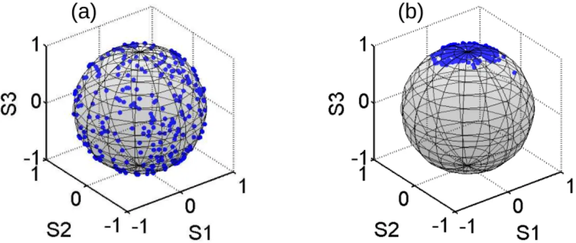
Figure 2a shows on the Poincaré sphere, the polarization state of the 10-Gbit/s signal at the input of the system. Because of the polarization scrambling process, the points are uniformly distributed onto the sphere. When the counter-propagating pump wave is injected into the optical fiber with a 600-mW average power, we clearly observe that most of the points are localized into a small area, indicating an attraction and stabilization of the polarization state of the signal wave (Fig. 2b).
Figure 2. State of polarization of the 10-Gbit/s signal plotted on the Poincaré sphere (a) At the input of the system (b) At the system output with a 300-mW signal average power and 600-mW pump power.
The efficiency of the polarization attraction process is more striking when directly monitored in the temporal domain. To this aim, we have inserted a polarization depending device, i.e. a polarizer at the output of the system (Pol in Fig. 1). We have then recorded the 10-Gbit/s output signal eye diagrams by means of a 30-GHz bandwidth oscilloscope. Figure 3 represents the eye-diagrams of the initially polarization scrambled signal monitored after the polarizer without (Fig. 3a) and in presence (Fig. 3b) of the counter-propagating pump beam.
In the pump-free configuration (Fig. 3a), the polarization fluctuations are transformed into intensity fluctuations through the polarizer, leading to a complete dramatic closure of the eye-diagram. By injecting the counter-propagating pump wave (Fig. 3b), a clear polarization stabilization is obtained. As can be seen, all the outcoming pulses have now almost identical polarizations, so that the opening of eye-diagram is now efficiently recovered.
Figure 3. Eye-diagrams of the 10-Gbit/s signal at the system output and monitored behind a polarizer (a) without and (b) in presence of the counter-propagating pump beam.
3.2BER measurements
We have also measured the corresponding bit-error-rate (BER) of the 10-Gbit/s signal as a function of the average power incoming on the receiver (Fig. 4a). The reference is illustrated by the back-to-back configuration (i.e. at the fiber input) in crosses. At the output of the system, when the polarization of the signal is scrambled, corresponding to the eye-diagram of Fig 3a, the BER is limited to 10-5 (triangle). When the counter-propagating pump wave is injected (circles), the quality of the transmission is greatly improved and low BER penalties were obtained on the receiver.
Figure 4. (a) Evolution of the bit error rate as a function of average power in back-to-back configuration (crosses); at the output of the system, with polarization scrambling and after a polarizer with (circles) and without (triangle) the counter-propagating pump beam (b) Intensity profile of the 6-ns polarization burst observed after a polarizer by means of a low bandwidth oscilloscope, without (dashed line) and with (solid line) counter-propagating pump wave
3.3Burst annihilation
Finally, we have monitored the ability of our system to annihilate a polarization burst, i.e. a strong and fast variation of the polarization signal state [12]. Such a dramatic event is fortunately rare but could be observed in a telecommunication line and is difficult to avoid with present systems based on active electronic feedback [13]. To this aim, a polarization burst, having a temporal width of 6 ns, was introduced into the initial 10-Gbit/s signal by means of a 15-GHz bandwidth optoelectronic polarization modulator.
Figure 4b shows the intensity profile of the polarization burst, observed with a low bandwidth oscilloscope at the output of the system and detected after a polarizer. In absence of counter-propagating pump beam (Fig. 4b dashed line), we observe a strong variation of the intensity, which could be disastrous for any polarization-sensitive component. When the pump beam is injected (solid line), the polarization burst was efficiently absorbed by the attraction process, leading to an error-free transmission (BER=10-12).
(b)
(a)
(100ps)
4.CONCLUSIONS
In conclusion, we have reported the first experimental observation of an all-optical polarization attraction process allowing control and stabilization of the state of polarization of a 10-Gbit/s optical signal at 1550 nm thanks to the injection of a counter-propagating pump wave, involving average powers below 1 W. We have also demonstrated that our optical device could strongly reduce intense and fast polarization variations as short as 6 ns. Based on these observations, we hope that this powerful system could foresee the state of polarization, neither as an elusive detrimental variable which has to be combated, but as a new parameter which could be tuned at will.
ACKNOWLEDGEMENTS
This work was supported by the Agence Nationale de la Recherche (ANR FUTUR project: ANR-06-TCOM-016) and by the Conseil Régional de Bourgogne.
REFERENCES
[1] K. Cvecek, K. Sponsel, R. Ludwig, C. Schubert, C. Stephan, G. Onishchukov, B. Schmauss, G. Leuchs, “2R-Regeneration of an 80-Gb/s RZ-DQPSK Signal by a Nonlinear Amplifying Loop Mirror”, IEEE Photon. Technol. Lett., vol. 19, pp. 146–148, 2007.
[2] E. Ip, A. P. T. Lau, D. J. F. Barros, and J. M. Kahn, "Coherent detection in optical fiber systems," Opt. Express, vol. 16, pp. 753-791, 2008.
[3] J. P. Gordon and H. Kogelnik, “PMD fundamentals: Polarization mode dispersion in optical fibers”, PNAS, vol. 97, pp. 4541-4550, 2000.
[4] J. Garnier, J. Fatome, and G. Le Meur, "Statistical analysis of pulse propagation driven by polarization-mode dispersion," J. Opt. Soc. Am. B, vol. 19, pp. 1968-1977, 2002.
[5] J.E. Heebner, R.S. Bennink, R.W. Boyd and R.A. Fisher, “Conversion of unpolarized light to polarized light with greater than 50% efficiency by photorefractive two-beam coupling”, Opt. Lett., vol. 25, pp. 257-259, 2000.
[6] M. Martinelli, M. Cirigliano, M. Ferrario, L. Marazzi, and P. Martelli, "Evidence of Raman-induced polarization pulling," Opt. Express, vol. 17, pp. 947-955, 2009.
[7] L. Thevenaz, A. Zadok, A. Eyal and M. Tur, “All-optical polarization control through Brillouin amplification”, in Optical Fiber Communication Conference OFC 2008, paper OML7.
[8] A. Zadok, E. Zilka, A. Eyal, L. Thévenaz, and M. Tur, "Vector analysis of stimulated Brillouin scattering amplification in standard single-mode fibers," Opt. Express, vol. 16, pp. 21692-21707, 2008.
[9] J. Fatome, S. Pitois, and G. Millot, "Experimental evidence of Brillouin-induced polarization wheeling in highly birefringent optical fibers," Opt. Express, vol. 17, pp. 12612-12618, 2009.
[10] S. Pitois, G. Millot, and S. Wabnitz, "Nonlinear polarization dynamics of counterpropagating waves in an isotropic optical fiber: theory and experiments," J. Opt. Soc. Am. B, vol. 18, pp. 432-443, 2001.
[11] S. Pitois, J. Fatome, and G. Millot, “Polarization attraction using counter-propagating waves in optical fiber at telecommunication wavelengths,” Opt. Express, vol. 16, pp. 6646-6651, 2008.
[12] M. Boroditsky, M. Brodsky, N. J. Frigo, P. Magill, and H. Rosenfeldt, “Polarization dynamics in installed fiberoptic systems,” IEEE LEOS Annual Meeting Conference Proceedings (LEOS), pp. 413-414, 2005. [13] M. Martinelli, P. Martelli, and S. M. Pietralunga, “Polarization stabilization in optical communications