HAL Id: inria-00147944
https://hal.inria.fr/inria-00147944
Submitted on 21 May 2007HAL is a multi-disciplinary open access archive for the deposit and dissemination of sci-entific research documents, whether they are pub-lished or not. The documents may come from teaching and research institutions in France or abroad, or from public or private research centers.
L’archive ouverte pluridisciplinaire HAL, est destinée au dépôt et à la diffusion de documents scientifiques de niveau recherche, publiés ou non, émanant des établissements d’enseignement et de recherche français ou étrangers, des laboratoires publics ou privés.
State of the art in Wireless Mesh Networks - delivrable
L3.01 - RNRT project ”Airnet”
Cristian Popi, Olivier Festor
To cite this version:
Cristian Popi, Olivier Festor. State of the art in Wireless Mesh Networks - delivrable L3.01 - RNRT project ”Airnet”. [Research Report] 2007, pp.28. �inria-00147944�
AIRNET
Delivrable L3.01
state of the art in Wireless Mesh Networks Management
Cristian Popi & Olivier Festor
Contents
1 Introduction 3
2 Fault Management 3
2.1 System Overview . . . 5
2.2 The Accuracy of the Proposed Scheme . . . 6
2.3 Finding and Diagnosing Faults . . . 6
2.3.1 Simulation Methodology . . . 6
2.3.2 Fault Diagnosis Algorithm . . . 7
2.3.3 Handling Imperfect Data . . . 7
2.4 Evaluation . . . 8
2.5 Remarks about the approach employed for Fault Management . . . 8
3 Configuration Management 8 3.1 Configuration Overview . . . 10
3.1.1 Configuration of the NOSS . . . 10
3.1.2 Configuration of network elements . . . 13
3.2 Prerequisites for Configuring a Nortel based WMN . . . 14
3.3 Centralized management in the Nortel approach . . . 14
3.4 Mobility Management . . . 14
3.5 Power management . . . 15
4 Accounting Management 15 4.1 RADIUS . . . 15
4.1.1 Overview . . . 15
4.1.2 Accounting server configurations . . . 16
4.1.3 The case of a mobile node joining the network . . . 17
4.1.4 RADIUS server accounting attributes . . . 17
4.1.5 Tracking of services and resource usage . . . 17
5 Performance Management 18 5.1 Critical factors influencing network performance . . . 18
5.2 Network monitoring . . . 19
5.2.1 Performance parameters . . . 19
5.2.2 Monitoring Framework . . . 20
6 Security Management 22 6.1 Security Challenges of WMNs . . . 22
6.2 Fundamental Security Operations . . . 23
6.2.1 Detection of Corrupt TAPs . . . 23
6.2.2 Secure Multi-hop Routing . . . 24
6.2.3 Fairness . . . 24
6.3 ARSA . . . 24
6.3.1 Authentication and Key Agreement (AKA) . . . 25
6.3.2 Security Enhancements . . . 25
List of Figures
1 Wireless Mesh Network – abstract layered view . . . 4
2 Wireless Mesh Networks – a community network example . . . 4
3 Fault Detection Scheme . . . 5
4 Nortel architecture – basic WMN . . . 9
5 Flow of a Configuration Task . . . 11
6 The Flow for the Configuration process of Network Elements . . . 13
7 A Nortel WMN architecture for accounting and authentication . . . 16
1
Introduction
This delivrable presents a state of the art on management related issues in Wireless Mesh Networks. We describe existant work focusing on the five functional domains of the management plane: fault management, configuration management, accounting, performance and security. Each chapter presents work related to the aformentioned functions. First, though, we define our view of a Wireless Mesh Network, in the following subsection.
Wireless mesh networks extend the Wireless LAN architecture by providing wireless connections between Access Points (AP), thus enlarging the surface of coverage, and allowing for a cheap deployment of internet access where cabling is costly (ie. high density of users).
The architecture of a WMN is two tiered, with the layers consisting of: access points on one side, and client nodes on the other side. We will proceed with descriptions for both levels of nodes and will exemplify a global architecture of a WMN.
The access points form a mesh of fixed nodes, also known as the network infrastructure, or backbone. The backbone can rely on various radio technologies (amongst which IEEE 802.11) for interconnection. The access points have a double function: that of providing access to roaming clients, and of relaying data for other routers which communicate with each other in a wireless multi-hop manner. Some of the routers act as gateways for connectivity with other wireless mesh networks, or other types of networks, including wired ones (see fig 1). The interconnection feature of wireless mesh networks allow them to provide internet services to their clients. [5] defines mesh routers that act as gateways, as Wireless Hot Spots (WHS), and the relaying nodes as Transit Access Points (TAP).
The clients are devices with wireless capabilities, that is they have a wireless interface, typically laptops, PDAs or IP phones (but not restricted to these – a desktop can very well constitute a WMN client if it is within a mesh router’s transmission area). They connect to the network by positioning themselves in the accesability area of a mesh router, which relays their packets to/from the desired destination. According to [4] (see the descriptions of Client WMNs and Hybrid WMNs) and [12], the clients can form an ad-hoc network by adding extra functions (ie. routing), either for relaying packets for clients that are out of the reachability of access points, either for directly communicating between themselves in a peer-to-peer manner (fig. 1).
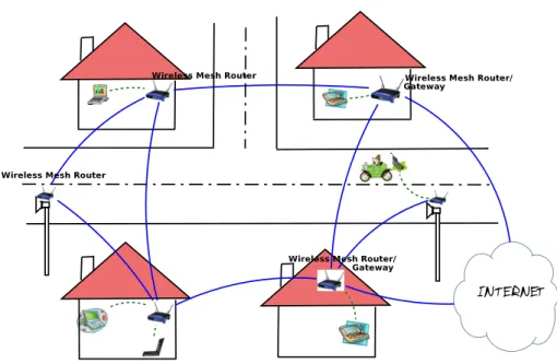
In our approach we tackle the concept of community networking. This means set-up of a wireless mesh network with several access points (mesh routers), having a low degree of movement, present in a close vicinity (ie. neighborhood of houses), and mobile clients (such as laptops, PDAs, IP phones) connecting to these routers as they roam by, and transfering files, streaming multimedia between themselves, or accessing the Internet, if there is a mesh router with a gateway function in the network. An example of a Wireless Mesh Network is depicted in fig. 2.
2
Fault Management
Lili Qiu et al, in [10], present a solution for fault management in the context of Wireless Mesh Networks. The approach is based on trace-driven simulations and a set of “known” fault models. It enables the detection of faults in real-time. The motivation beyond a simulation driven fault detection scheme is drawn from the difficulties encountered when troubleshooting Wireless Mesh Networks: unreliable physical medium, fluctuating environmental conditions, complicated wireless interference and limited network resources.
Figure 1: Wireless Mesh Network – abstract layered view
WMN Simulator Network Topology Interference Injection Fault Directory =? Data Cleaning Module Network Reports link RSS link load topology updates
link loss rates & throughput
error
(Link, Node, Fault)
error
Root cause analysis module
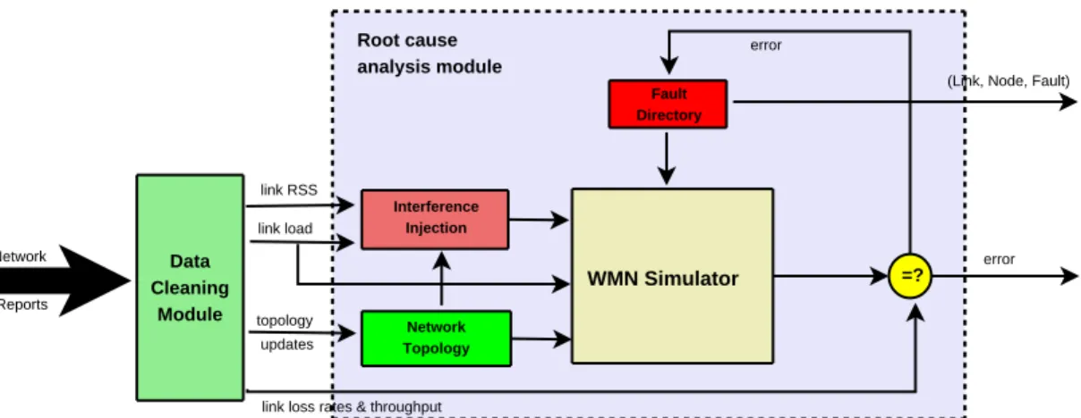
Figure 3: Fault Detection Scheme
2.1 System Overview
There are two kind of entities in the system as far as management is concerned: the manager (managers for the case of distributed management) and agents (entities that are being managed). They are implemented as modules running on the nodes of a Wireless Mesh Network. The agent module runs on every node, gathers information from various protocol layers and sends it to the manager. The manager analyses the data and takes appropriate actions.
The troubleshooting process involves three steps: data collection, data cleaning and root cause analy-ses. Data collection is done on the agents side, and information is continuosly transmitted to the manager. The information sent includes traffic statistics (ie volume of traffic sent/received from neighbors for each node), received packet signal strength on various links, and retransmission counts on each link. While it is possible for the manager to receive inconsistent data from different agents (these inconsistencies could be the result of topological and environmnental changes, measurements errors, or misbehaving nodes), the
Data Cleaning module takes care of this by resolving inconsistencies before data is fed into the analysis module (see section 2.3.3).
Finally the Root Cause Analysis module gets the cleaned trace data and drives the simulator contained within (see fig. 3) to obtain a performance, that is considered to be the normal, or baseline behavior. On the other hand, observed performance of the Wireless Mesh Network (characterised by such parameters as link loss rate and throughput) is led into the Root Cause Analysis module (but not into the simulator). This data is compared with the baseline behavior such that any significant deviation implies a potential fault in the network. Root cause for the difference in behavior is determined by searching for a set of faults (predefined in the Fault Directory) that, when input into the simulator, generate the same performance as the observed network performance.
The rationale for building such a system is that a simulator is customizable and can be applied to a large class of networks under different environments. An architecture that uses such a simulator for fault diagnosis inherits this generality.
There are a couple of problems with building a troubleshooting architecture based on a simulator. The first and foremost is the accuracy of the simulator. Qiu et all (in [10]) prove that for the purpose of fault diagnosis trace-based simulations are accurate enough to reproduce what happened in the real network. Next we present what simulator accuracy means in term of the fault management scheme.
2.2 The Accuracy of the Proposed Scheme
There are factors like RF (Radio Frequency) environmental conditions and presence of obstacles, or variability of hardware performance that make it difficult for a network simulator to model wireless mesh networks accurately. This is sought to be solved by the authors by replacing theoretical models from the simulator with data obtained from the network.
In order to quantify the accuracy of simulating the overhead of the protocol stack and the effect of RF interference, they make some baseline comparisons between the performance of the real network and the performance of the simulator. The experimental scenarios show that the simulator accurately takes into account contention from flows within interference and communication ranges.
Another factor’s influence on the performance of the real network should also be quantified for the simulator: the RSS (Received Signal Strength on a link). The influence of RSS on throughput is caught in two situations:
1. signal quality is good (that is, there are a few walls or obstacles between nodes). In this case, the measured throughput approximates well the simulator estimate
2. signal strength is poor (that is, there are more walls or obstacles between nodes). In this case, throughput estimated by the simulator deviates because the simulator doesn’t take into account packet loss (as a function of packet-size, RSS and ambient noise - this depends on the signal processing hardware on the wireless card) and auto-rate control.
Auto-rate control is a software mechanism on the wireless cards which adjusts the sending rate of the card, if the retransmission rate at the MAC layer is high. If this is in use anywhere in the real network then the rate at which the wireless card is operating is monitored and provided to the simulator.
To solve the packet loss simulation issue, an offline analysis is done, where a database is created to associate environmental factors with expected performance (a mapping from signal strength and noise elvels to loss rate). This approach can distinguish from losses caused by collisions and losses caused by RF conditions, and has a high feasability.
2.3 Finding and Diagnosing Faults
Using traces, the network topology and traffic patterns from the real network are reproduced into the simulator. With the trace-driven simulation already established, an algorithm for root-cause search is developed.
2.3.1 Simulation Methodology
Collection of Trace Data Traces from the real network (from each node in the network, in particular) are sent to the manager. Here, they are fed into the simulator so as to capture the running state of the real network and find out the effects of faults on it. These traces are sets of data describing changes in the sets of neighbors of each node, traffic statistics (ie. volume of traffic sent to or received from neighbors), nose level and signal strength on the links to neighbors and network performance (link performance and end-to-end performance in particular, measured by metrics like packet loss rate, delay and throughput).
There are two distinct steps in the collection of traces:
a) local data collection; tools like SNMP, packet sniffers (Airopeek, WRAPI, Native 802.11) are appro-priate for use in collecting data,
b) distributing the data to a manager; this introduces overhead, which Qiu et al show is low and has little impact on data traffic.
Simulation Network characteristics are classified into 3 groups: traffic load, wireless signal, and faults. We shall discuss each of them in part.
For the traffic load there are two possible simulation approaches: end-to-end application demands, or link-based traffic simulation. Link-based traffic simulation is preferred for scalability, but matching the observed link-level traffic in the simulator is not trivial. The authors therefore sought to control the sending rate on a link by adjusting the application-level sending rate. On top of that, interference introduces inter-dependency between sending rates on different links. This makes it even more difficult to simulate the load on a link. An algorithm has been devised that addresses this issue, which uses iterative search (based on multiplicative increase and multiplicative decrease).
Simulation of wireless signal is driven using real measurements of signal strength and noise.
Faults have to be able to be introduced into the simulator in order to examine their impact on the network. Four types of faults are taken into account for fault injection:
1. Packet dropping at hosts – detection of this fault is usefull in order to differentiate losses caused by end hosts from those caused by network
2. External noise sources
3. MAC misbehavior – a faulty node would, for instance, modify the Contention Window (CW) to obtain an unfair share of channel bandwidth
4. Link congestion – this fault is generated by injecting a high load on the network, and is readily captured by traffic statistics collected from nodes
2.3.2 Fault Diagnosis Algorithm
Given the possible types of faults that may occur in the network (as previously classified), an algorithm is next presented, that detects root-causes for faults. The problem is reduced to searching the fault space for errors that, when injected into the simulator, generate the same performance as the observed performance. Or, formalised: given N S, the network settings, a F aultSet has to be found such that
SimP erf ormance(N S, F aultSet) ≈ ObservedP erformance
The search space is high-dimensional, due to many fault combinations. But the search process is easened by the observation that different types of faults change only one or a few metrics. Thus the algorithm determines the type of fault using a decision tree, with faults being categorized by checking the differen-tiating component.
2.3.3 Handling Imperfect Data
Raw trace data collected may contain errors. Steps taken for cleaning the data are:
a) neighbour monitoring – each node reports statistics not only for its adjacent links, but also for links in its communication range (possible if a node is in promiscuous mode under Native 802.11)
b) detecting inconsistency – this is done by using redundant information from multiple reports; a scheme using an inconsistency graph is implemented to achieve this
2.4 Evaluation
Different evaluation stages are employed to verify the validity of the approach. First, the data collection overhead is shown to be low and with little effect to application data in the network. Next an evaluation of the fault diagnosis is done. The method employed is the following:
a) a set of faults are intentionally injected into the network
b) traces of network topology and link load under faults (the ones formerly injected) are collected c) these traces are fed to the fault diagnosis module
d) root cause is inferred based on the difference between expected and actual performance
e) diagnosis accuracy is then drawn from the difference between the original and inferred fault sets A verification of the data cleaning scheme shows that the accuracy of detecting misbehaving nodes is high. Different scenarios also show that topologies with high node density have high detection accuracy and that history information improves detection accuracy.
As a conclusion, the authors identify some possible add-ons to the functionality of this scheme. Incorporation of security schemes, like cryptographic schemes for authentication and integrity, is viewed as a challenging follow-up. Another “to do” is investigate techniques for incomplete data (obtained from a subset of the network), with direct influence on the scalability of the troubleshooting system.
2.5 Remarks about the approach employed for Fault Management
The paper gives a solution for a fault management scheme based on troubleshooting a WMN with the help of a simulator. While this is a novel idea, it comes with a set of complex problems that need to be solved in order to be able to take full advantage of this approach. The rigidity of modeling the lower layers protocols in the simulator is tackled with by replacing them with real data (obtained from traces) which accurately model the variability of hardware performance, RF environmental conditions or presence of obstacles. Another potential problem that is handled in this paper is the inconsistency in the data transmitted from the managed agents to the manager. To solve it, a scheme is introduced for detecting inconsistencies in the trace data collected from agents, and for keeping records of misbehaving agents.
The module in this paper is only presented for a centralised management scheme. Although the author mentiones the possibility of running a distributed manager, she doesn’t show how this scheme can be extended to a cooperative (distributed) manager environmnet. A monitoring tool is said to have been implemented, which as described in Section 6, could provide a good starting-point for a configuration manager, but no extensive description of it is provided.
3
Configuration Management
For the configuration management process of Wireless Mesh Networks (WMNs) commercial solutions already exist. We focus here mainly on two products offered by Nortel and LocustWorld [1].
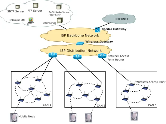
For a better understanding of the configuration process we will give a short description of a wireless mesh network architecture suggested by NORTEL [2]. The network consists of the following parts: Community Area Network, Network Access Point, Wireless Access Point, Wireless Bridge, ISP backbone network, Wireless Gateway, Border Gateway, Network Operations Support System, Wireless Mobile Node, Inter-Wireless Gateway (fig. 4).
Figure 4: Nortel architecture – basic WMN
The Community Area Network (CAN) is identified in our model by the infrastructure of a WMN, or a group of mesh routers (wireless access points) that form a solf-organizing and self-configuring mesh structure. The CAN (Community Area Network) uses a multi-hop, wireless backhaul from a wired broadband network access point (NAP). Each wireless access point in a CAN is configured with the same software version.
A Network Access Point Router (NAP-R) connects a Community Area Network (CAN) to the distribution network. The NAP incorporates routing functions and multiple wired Ethernet links that connect to one or more of the wireless access points in a CAN.
A Wireless Access Point collects and distributes traffic within the Community Area Network. It acts as a DHCP client for itself, as a DHCP relay for mobile nodes and for neighbor Wireless Access Points. It is also a RADIUS Authentication Client for mobile nodes and for neighbor Wireless APs, and a RADIUS Accounting client for mobile nodes.
The ISP backbone network is a Layer 3 routed domain (IP routing decisions are made by the backbone network). It is used to carry IP traffic between the Wireless Gateway and other elements of the Enterprise/ISP network (ie. NOSS servers)
The Wireless Gateway advertises reachability (within the ISP Distribution Network) for IP subnets assigned to Community Area Networks subscribers and network entities. It hides wireless mesh network specific mobility and security functions from the rest of the Distribution and Backbone Networks.
The Border Gateway is a logical network entity which functions as an interface with the Internet. It advertises reachability to the Internet for IP addresses assigned to WMN subscribers and network entities (also non-WMN ISP entities).
The ISP Backbone Network carries IP traffic between the Wireless Gateway and other internal elements of the IPS network, like the Network Operations Support System (NOSS) servers or the Border Gateway.
The ISP Distribution Network carries IP traffic between the Wireless Gateway and the Network Access Points Routers (NAP-R)
The Simple Network Time Protocol (SNTP) server’s role is to provide each wireless AP with time parameters so that they can then correctly attach time-stamps to the events associated with each of them.
The Network Operations Support System (NOSS) is a block that offers centralized monitoring, managing operations and interfacing to the distributed elements in the Wireless Mesh Network using such protocols as SNMP, DHCP or RADIUS. The NOSS consists of the Enterprise Network Management System (ENMS), FTP, RADIUS, DHCP and SNTP servers. The Enterprise Network Management System (ENMS) provides fault, performance and configuration management and discovers wireless APs. The DHCP server provides dynamic IP addresses for wireless APs and mobile nodes. The RADIUS server performs mobile and wireless AP authentication, authorization and accounting. The FTP server stores configuration files that the wireless APs accesses (by downloading) when turned on. It also consists of software for the wireless APs. The SNTP server provides the wireless APs time parameters that it needs for timestamp-ing events.
The Network Access Controler (NOC) is responsible for controlling the mobile traffic going in and coming out of the Community Area Network (CAN). It also ensures the all mobile subscribers are authenticated before mobile node traffic can flow through.
After having defined the main elements of a proprietary comercial Wireless Mesh Network, let us look at how the tasks flow for the configuration of a Wireless Mesh Network, as that of a WMN solution provided by Nortel [2], looks like, in figure 5.
3.1 Configuration Overview
In order for a Wireless Mesh Network to be set up, some or all of the following tasks have to be performed: • Configuration of the NOSS
• Configuratin of the Network Access Controller (NAC) • Configuration of the network access point (NAP-R) router • Configuration of the Wireless Gateway
• Configuration of the Wireless Access Points 3.1.1 Configuration of the NOSS
Nortel provides a Network Operation Support System (NOSS), which assures centralized facilities for monitoring and managing network operations and communicates with distributed distributed elements in the Wireless Mesh Network by standardized protocols. All NOSS elements are configured on the private side of the Wireless Mesh Network.
The NOSS has the following components:
• Nortel Enterprise Network Management System (ENMS) • Dynamic Host Configuration Protocol (DHCP) server
• Remote Authentication Dial-In User Services (RADIUS) server • File Transfer Protocol (FTP) server
Wireless Mesh Network Configuration Configuration of the NOSS Configuration of the network elements Configuration of the Wireless Gateway Configuration of the Wireless Access Points End
Figure 5: Flow of a Configuration Task
Configuration of the Dynamic Host Configuration (DHCP) server The DHCP server provides dynamic and static IP address assignments for the wireless mesh routers as well as for the mobile nodes. A reserved configurable lease timer must be supported by the DHCP server.
The DHCP server is used for the configuration of wireless mesh router parameters like: IP address, subnet mask, public IP address of the Wireless Gateway, address lease time, FTP server IP address, wireless mesh routers configuration filename.
Mobile node parameters that are configured with the DHCP server are: • IP address of the mobile node address pool for eash SSID subnet • subnet mask for the mobile node address pool previously configured • address lease time
• home agent IP address
• default router (must be on the same subnet as the mobile node)
Static IP addresses can be assigned for any node in the network by including a host declaration in the DHCP configuration file. The host declaration should contain for each added node, be it wireless mesh router, or mobile node, the MAC address. The static and the declared range of dynamic IP address must be on the same subnet, but their intersection should be null.
The DHCP server’s IP address can be hidden from the mobile subscribers (if such is desired) by simply replacing it with a dummy DHCP server IP address in the mobile node sectin of the DHCP configuration file.
Configuration of the RADIUS server The RADIUS server in the NOSS can be configured to provide:
• RADIUS authentication, authorization and accounting (AAA) services for SSIDs in the Wireless Mesh Network
• RADIUS proxy services for RADIUS AAA servers that are located in the service provider’s network operations center (NOC)
Wireless mesh networks and mobile nodes in the Nortel solution are all authenticated using the RADIUS AAA server. This supports user authentication based on a native database or through backend servers.
If the Wireless Mesh Network operator manages the authentication and accounting functions for all the SSIDs in the WMN, the RADIUS AAA server and the proxy functions can lie on the same physical network element in the NOSS. The RADIUS proxy function is not needed if authentication and authorization are based on a combination of the User-Name and Called-Station-ID RADIUS attributes. For communication with mobile nodes, parameters like: Called-Station-ID (used as an additional authentication attribute to the username and password), Tunnel-Private-Group-ID (returned by the RA-DIUS server in Access-Accept messages), Calling-station-ID (parameter set to the MAC address of the mobile node inserted by the wireless mesh router to which the mobile node is associated).
An account on the RADIUS server must be created for each wireless mesh router.
The RADIUS proxy server is used for relaying authentication and accounting messages from the Wire-less Mesh Network to the RADIUS AAA servers and vice-versa. The RADIUS proxy server’s configuration supports:
• proxy functins based on the Called-Station-ID attribute of the RADIUS request for authentication and accounting requests.
• RADIUS attribute filtering so that RADIUS attributes mandatory for the WMN, but optional for the ISP RADIUS server (such as Tunnel-Group-ID attribute) cand be added, or such that RADIUS attributes returned by the ISP RADIUS server can be modified and mapped to the ones used internally by the WMN (such as Tunnel-Assignment-ID)
Configuration of the FTP server The FTP configuration file is used for automatic configuration by the wireless mesh router. Such a file can be created for each wireless mesh router or for a group of wireless mesh routers.
The FTP server is used for:
• downloading the configuration file to the wireless mesh router • upgrading software to the wireless mesh router
• upgrading software to the Wireless Gateway
• saving and backing up the Wireless Gateway configuration files • storing wireless mesh router logs
A user account containing the username and password for FTP access must be configured both at the FTP server side and the wireless mesh router.
Configuration of the Network Elements Configuration of the Network Access Controller (NAC) Configuration of an Ethernet switch Configuration of the RADIUS server
Figure 6: The Flow for the Configuration process of Network Elements
Configuration of super ping in ENMS (Eurovision Network Management System) Super ping in ENMS allows the Wireless Gateway or any wireless mesh router to be polled with the help of a ping message. For instance in the Nortel implementation, for a 64 devices network, each device receives one ping message every 55 milliseconds. Reconfiguration of the ping message frequency according to network size is recommended.
3.1.2 Configuration of network elements
The configuration of the network elements is accomplished according to the task flow in the figure 6 Configuration of the Network Access Controller (NAC) The Network Access Controller (NAC) for a gateway between Wireless Mesh Networks is responsable for advertising the range of reach of a subset of mobile nodes to the external and internal networks in order to have ”contact” with other devices in the network.
NAC has to support: • Ethernet interface
• configurable ARP cache size • configurable ARP age out time
• updatable ARP cache upon receiving a unicast ARP request • packet forwarding either through dynamic or static routing • mobile session idle timeout
• client filter and access rules to stop mobile nodes from accessing the internal network elements of the Wireless Mesh Network
The web portal URL must be configured to redirect the mobile node session for authentication. NAC should block all mobile traffic until the mobile subscriber is authenticated.
Configuration of the NAP router As for the configuration of a NAP router, any router that can support OSPF (OSPF is a link-state, hierarchical interior gateway protocol used fot network routing, whith cost as its routing metric) can be configured as a NAP router for the WMN. The NAP router should have the ability to propagate route information into the Community Area Network (CAN).
3.2 Prerequisites for Configuring a Nortel based WMN
DHCP server requirements The DHCP server provisions the following configurations for the Wire-less Access Points: the address pool, the subnet mask, the default routers, the address lease time, the location of the configuration file (FTP server address) and the name of the configuration file, the Open Shortest Path First (OSPF) area ID, the Wireless Gateway IP address and the mobile home agent IP address.
The DHCP server provisions the following configurations for the mobile nodes: the address pool and subnet masks, the default Wireless Gateway router intranet IP address, the address lease time and the mobile home agent IP.
In order to do this, the DHCP server has to support the RFC 3011 subnet selection option, and to have a reserved lease time set to be high in order to provide for the possible delays incurred with the multiple Wireless APs hops.
RADIUS server requirements The RADIUS server should be able to support the Extensible Au-thentication Protocol (EAP), to generate master keys, and to provide tunnel support (after auAu-thentication of a user, a tunnel-ID linked to the user’s profile is returned to the Wireless AP).
FTP server requirements The configuration file of a Wireless AP (used to dynamically configure the Wireless AP when it initializes), as well as software upgares for both Wireless APs and the Wireless Gateway are all downloaded from the FTP server. The parameters that must be configured at the FTP server are it’s IP address, the user names for file access, and the password to access the configuration files or the software images.
3.3 Centralized management in the Nortel approach
It is at NOSS level that the management of network operations and monitoring functions are provided. The Nortel Enterprise Network Management System (ENMS) consists of tools that manage and visualize the Wireless Mesh Network and the important elements in it. It is based on the Simple Network Manage-ment Protocol (SNMP). The access to the manageManage-ment functions provided by ENMS can be established from various locations using a ENMS client, or a web browser.
Based on the number of supported WMN nodes, certain options are available for ENMS ranging from ENMS Campus (500 IP nodes) to ENMS Enterprise (5,000 IP nodes and even 10,000 with an upgrade to ENMS). ENMS offers graphical views of Layer 1,2 and 3 devices, network topology, faults and real-time performance statistics.
The drawback of the approach is the single point of failure for managing fault and performance across the network and the complexity it incurres with a high number of nodes to manage.
3.4 Mobility Management
Mobility management is an important part of Wireless Mesh Networks (WMNs) management, as nodes can roam across different Access Points (or Mesh Routers), or even between different WMN operators, thus having direct influence on the configuration, accounting or security of this kind of networks. The principal preocupations of mobility management are:
• location management – deals with location registration and call delivery
• handoff management – deals with handoff initiation, new connection generation, data flow control for call handoff
Distributed mobility management is a preferred solution for WMNs due to its decentralised architecture. Location service, according to Akyildiz, can enhance the performance of the MAC and routing protocols.
3.5 Power management
In WMNs, power usage is different among categories of nodes. The wireless mesh routers (or Access Points) are high power nodes. This feature comes mostly from the fact that they are fixed and thus permanently connected to an energy source. On the other hand, user nodes are typically low power energy constrained devices, like notebooks or PDAs, having a wireless interface card that run on batteries.
Because of the mobile nodes’ sensitivity to energy, the power management is meant to control the connectivity of the device, the interference, the spectrum spatial-reuse and topology.
A reduced power level means a reduced interference. This in turn has an impact on the spectrum spatial-reuse efficiency, but also impacts on the performance, as a degradation is observed in the MAC level, due to more hidden nodes.
4
Accounting Management
Authentication and authorization is already a solved issue in wireless LANs. Some commercial WLAN implementations provide AAA (authentication, authorization and accounting) services directly through the wireless LAN access point, or via gateways. AAA is usually realised through a centralized server such as RADIUS (remote authentication dial-in user service). While Akyildiz in [4] argues that the centralized scheme is not scalable in Wireless Mesh Networks, there is a commercial implementation, namely that of Nortel, that makes intensive use of RADIUS.
We will, therefore, focus on the Nortel approach and see how RADIUS is used to solve the AAA issue.
4.1 RADIUS
4.1.1 Overview
With RADIUS, a wireless mesh router operates as a client for the Network Operation Support System (NOSS) RADIUS server.The mesh router is the one responsable for passing mobile node accounting information to the RADIUS server in the NOSS (Network Operation Support System – read about NOSS in section 3.1.1 on the configuration of the NOSS, earlier in the document).
In the case where all accounting requests are handled by the NOSS RADIUS server, all accounting data goes to the accountig server on the NOSS RADIUS server. Otherwise (ie, multiple accounting servers are required to support multiple bunches of services), the NOSS RADIUS proxy server relays the accounting messages to the appropriate RADIUS accounting server. The accounting server can be in the same NOSS as the proxy server (see fig. 7), or it may be located on a RADIUS server in an ISP NOC (Network Operations Center).
The RADIUS accounting server receives the accounting request from a wireless mesh router, and acknowledges it, either directly or via the NOSS RADIUS proxy server.
The RADIUS server can track different kind of mobile nodes:
• Robust Security Network Assciation (RSNA) mobile nodes which use WPA-EAP/802.1X authen-tication – these type of nodes are tracked on the RADIUS server by the user name supplied by the mobile node
• RSNA mobile nodes using WPA-PSK authentication and non-RSNA mobile nodes – these type of nodes are being tracked by the user name supplied by the Virtual Access Point (VAP) for the
Figure 7: A Nortel WMN architecture for accounting and authentication
mobile node; this user name is configured via the FTP configuration file such that it can be one of the following:
– the MAC address of the mobile node
– the Service Set Identifier (SSID) used by the mobile node to associate with the Virtual Access Point (VAP)
– ”UNKNOWN” ASCII string for an anonymous user 4.1.2 Accounting server configurations
An IPsec tunnel is created through the Wireless Gateway (identified during wireless mesh router initial-ization and configuration) for communication between the wireless mesh router and the RADIUS server in the Network Operation Support System (NOSS).The Wireless Gateway’s sole purpose is to forward the accounting information between the wireless mesh router and the RADIUS servers in the NOSS. Nortel’s implementation supports the following configurations:
• Separate Authentication and Accounting servers: the wireles mesh router has to be configured with the address of both servers. Access-request packets are sent to the authentication server, and accounting-request packets to the accounting server
• Integrated Authentication and Accounting server: in this case the wireless mesh router has to be configured with the address of the common server.Access and accounting requests are sent to the same RADIUS server
• Primary and Secondary servers: the Network Operation Support System (NOSS) is configured with backup servers that can take over a primary’s authentication/accounting server’s role in case of a primary server failure
4.1.3 The case of a mobile node joining the network
When a mobile node joins the network, it must first authenticate itself, so that permissions and billing policies be settled.
In order for a node to be authenticated, it must be matched to a profile stored on the server. If there is a match (node authenticated), a Tunnel-ID stored in the profile is returned to the wireless mesh router. The wireless mesh router then maps the Tunnel-ID to the Subnet Selection Option (SSO). This mapping exists in the wireless mesh router configuration file.
When the mapping is done, the DHCP Relay Agent on the router requests a session IP address for the mobile node from the DHCP server. If the RADIUS server is used for authentication of the wireless mesh router, the RADIUS server must support LEAP (Lightweight Extensible Authentication Protocol) authentication based on the User-Name attribute only.
4.1.4 RADIUS server accounting attributes
Next we describe a few of the RADIUS server accounting attributes: • user-name – identifies the user; see section 4.1.1
• NAS-IP Address – this attribute identifies the IP address of the wireless mesh router requesting authentication on behalf of the mobile node
• Framed-IP-Address – indicated the IP address assigned to the mobile node
• Called-Station-ID – indicates the type of authentication used by the VAP (Virtual Access Point) in a Wireless Access Point, in the case a single Access Point is shared by multiple providers; • Calling-Station-ID – indicates the MAC address of the mobile node
4.1.5 Tracking of services and resource usage
As shown in section 3 a Wireless Gateway’s role is to advertise reachability for IP subnets assigned to Community Area Network entities. (4
A mobile node is being tracked by the wireless gateway by being issued a multi-session ID (MSID) when the mobile node first associates with the wireless mesh router. The wireless gateway generates a new session ID (SID) for each mobile node connection.
When the node moves accross multiple wireless mesh routers (Wireless Access Points), the Wireless Gateway retains the multi-session ID (MSID) and passes it to the Wireless APs under whose coverage the mobile node is, so that these can further include it (the MSID) into RADIUS client accounting messages, for logging.
Time-based accounting Each user has a session duration. When the multi-session ID (MSID) for a user (mobile node) is generated, a start message is sent to the RADIUS server from the Wireless Gateway. A stop message is sent when the user session has finished. The timestamps of these messages are local to the RADIUS server (who actually adds these timestamps to the messages). The complete session length is thus calculated; this allows for a billing of services acording to the time spent in the network.
Because one MSID (multi-session ID) is used for the whole session, the roaming of a node from a Wireless AP to another one will not affect the accounting information for that user.
In case there are multiple start and stop messages, only the first start and last stop message with the same MSID count towards computing the session time.
Idle timeouts A user is idle in the network when, after a number of seconds (or minutes) he doesn’t have any activity. The idle timeout interval is the duration of time that passes from the start of an idle period till the moment the wireless mesh router (Wireless AP) terminates the user session. This interval is set on the RADIUS server for each user. For time-based accounting, the idle timeout interval value is deducted from the overall session time if the user terminated its session due to an idle timeout.
In the case of moving from one Wireless AP to another within the same sessio, the current Wireless AP sends an accounting stop message to the RADIUS server after the specified idle time has run out on the previous Wireless AP, or if the IPsec tunnel is manually torn down on the Wireless Gateway.
Network failure influence on accounting There are four types of failures that could affect accounting:
• Wireless AP failure • Wireless Gateway failure
• NOSS RADIUS server failure or ISP RADIUS server failure • IPsec tunnel teardown
If a Wireless AP fails, accounting stop messages would cease to be sent to the RADIUS server. The network operator must track the Wireless AP breakdown time to determine an approximate time for the termination of each session.
A Wireless Gateway failure has as consequence the termination of all user sessions, without any stop messages sent to the RADIUS server. The network operator will have to track down the time of the Wireless Gateway breakdown, and with the previous accounting information, retained on the RADIUS server, it can approximate session time for each of the users.
If a RADIUS server failure occures, all subsequent accounting messages are lost. It is desired to have a backup RADIUS server in the network.
An IPsec tunnel teardown on the Wireless AP impacts all the existing sessions (they are terminated). The Wireless AP reboots.
Fraud reporting If a node fails to authenticate, no accounting message for it is sent to the RADIUS server. If an unauthorized mobile node appropriates an authenticated session, the session is terminated and a stop message is sent to the RADIUS server, with the mobile node being quarantined form the Wireless Access Point.
5
Performance Management
5.1 Critical factors influencing network performance
The critical factors influencing the performance of a WMN network are: • radio techniques,
• scalability,
• mesh connectivity, • broadband and QoS,
• compatibility and inter-operability, • security,
• ease of use (management requirements: autonomy in power management, organization, dynamic topology control, robust to temporary link failure, fast network subscription/user-authentication procedure).
5.2 Network monitoring
In this subsection we will focus on monitoring Wireless Mesh Networks. Monitoring is essential in the management process because it provides vital information about the status of the network, whether it functions correctly or according to specific imposed QoS. It also gives supportive clues regarding possible enhancements on the management side that can, as a consequence, boost up performance perceived by the user (ie. throughput, ...). We cannot decouple monitoring from the parameters it surveys, therefore we will first take a look on network characteristics. After that, we introduce a monitoring framework [7] in which C. Ho et al present a scheme for single-hop wireless networks.
5.2.1 Performance parameters
By performance parameters we mean those characteristics of the network that, by alteration (be it slight or big), change the present running status of the network, not necessarily degrading its performance, or influence other characteristics (in a chain-like fashion). We summarily classify them as parameters pertaining solely to hosts (processing power, operability, radio power, etc) or parameters drawn from the interactions and dynamicity in the network (link quality, topology, etc).
While node characteristics per se are easy to report to a network manager (our case calls for a distributed self-management architecture [3]), the latter need more complex schemes to be extracted and subsequently reported. Moreover there are often non-trivial interactions between certain parameters like for instance topology and channel allocation in multi-radio mesh networks [9], or topology and interference [6].
Link quality
In [8], K. Kim introduces a scheme for accurate measurement of link quality in a wireless mesh network. Link quality experiences fluctuations and, often induces performance degradation. Accurately measuring it is therefore important for multiple reasons: routing (finding the best relay node), fault diagnosis (see section 2) or identifying high-quality channels.
The proposed architecture, EAR (Efficient and Accurate link-quality monitoR) uses distributed and periodic measurement of unicast-based uni-directional data probes (for preserving settings of actual data transmissions) by dynamically choosing one of three schemes: passive, cooperative and active. Passive measurement is done on a link where there is enough traffic from a node m, called the measuring node, to a neighbor n. When this traffic, also called egress traffic, decreseas below a certain (pre-established) threshold, if there is another neighbor, p, of the measuring node to which the latter has egress traffic that can be overheard by n, then the cooperative scheme is employed. The scheme takes advantage of the promiscuous mode in the 802.11 based Network Interfaces, which allows node n to capture the data sent by m to p (since n is in m’s transmission range). Measurements are done both in node m (number of sent frames) as well as in node n, the cooperative node (counts all received MAC frames), and in the end are merged at the measuring node, which derives link m–>n performance. Since retransmitting packets
induces ambiguity, and because the cooperative node, n, cannot receive duplicate frames from its MAC layer, the sender, m, has to disregard the retransmitted packets when measuring.
If there is neither egress nor cross traffic the passive scheme is enforced, with the measuring node, m, actively sending probes on the link to n and measuring the quality of the link. Various issues related to the influence active probing has over the network performance (ie. interference cause to other links – especially if the channel is already heavily used) enforce design approaches, like for instance, an activity-based backoff timer to provide for the case where there is not too much quality variance on a link.
Compared to previously existant tools (ie. Broadcast-based Active Probing) EAR is shown [8] to behave well in terms of accuracy, scalability and link asymmetry awareness.
Connectivity, topology and interference
In Wireless Mesh Networks, the links between nodes are, due to their wireless nature, configurable (ie. in terms of power level).
In [9] and [6], interference on the links is desired to be reduced by dynamically assigning interfaces in multi-radio nodes to different channels. A traffic independent base channel assignment is initially done, with a pair of nodes establishing a default channel (possibly different for different pairs of nodes) which will assure a subsequent coordination of the nodes (for the dynamically assigned channels) and aid in the reassignment of channels to interfaces.
The channel assignement process is an optimisation problem in which interference is sought to be reduced, better throughput attained, and connectivity maintained (as close as possible to the initial state). [9] proposes an algorithm, Connected Low Interference Channel Assignment (CLICA), which resembles a graph coloring algorithm in which a color is substituted for a channel. Because of the network connectivity constraint, making a coloring decision at a certain moment limits the flexibility of future coloring decisions.
The algorithm comports two stages. In the first phase, coloring is done for nodes in a sequence given by node priority, which is assigned at the beginning according to chosen criteria. The algorithm is an adaptive priority algorithm, as priorities can be modified during execution, if there are nodes which lack flexibility (ie. they only have one interface available for channel assignement). The procedure is done recursively on a chain of the least flexible nodes to ensure connectivity maintenance. For each recursion, the coloring decision is based on a greedy algorithm. As there are nodes who don’t have all their radios allocated to channels after the first stage, a second phase is needed. Here, either such a node attempts to find neighboring nodes with uncolored radios to set up a link on a chosen channel, either the unused radios are conserved for a later assignement, dynamically, based on traffic load. Moreover, such an approach can be forced by explicitly (before starting the algorithm) controlling the number of uncolored radios at the end of phase one.
The algorithm, as it is, has a centralised approach. Were it to be implemented in a distributed manner, it would lose from scalability because of the time incurred. The first phase could be distributed by exploring the connectivity graph via distributed depth-first search with token-passing starting at a designated node. Each node makes coloring decisions based on its own view of the conflict graph. The second stage can easily be implemented locally as it entails no risk of not respecting connectivity constraints.
5.2.2 Monitoring Framework
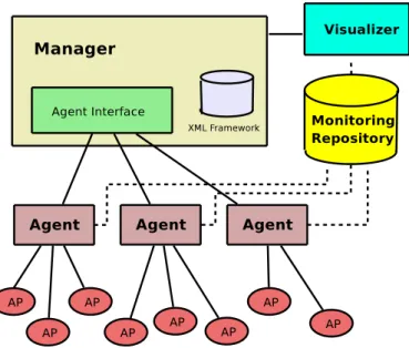
Analysis of collected network state data through monitoring provides for the development of a realistic data traffic model, inference of user mobility and building of wireless propagation models. [7] proposes VISUM, a framework for wireless one-hop network monitoring. The implementation allows visualization of
Figure 8: VISUM Architecture
collected data through interactive network topology maps or real-time statistical graphs and reports. The challenges that wireless networks bring are the diversity and the high development rythm of proprietary solutions, the network size (which rules out a centralized solution because of bad scalability) and the extensibility. Therefore, any monitoring architecture should be able to easily integrate new devices into their monitoring framework, or otherwise said, be able to cope with proprietary configuration schemes. The solution that [7] comes with and that is worth considering when designing a monitoring architecture for Wireless Mesh Networks, is a framework based on XML.
In VISUM (fig. 8) there is a central manager who coordinates the activity of a distributed set of
agents, and which is the central location for the configuration and maintenance of the agents. The one central manager solution is not in concordance with our envisaged self-managed architecture which eliminates the locality, and distributes the management tasks around the participating nodes. However the hierarchical structure of XML profile definitions, based on generality (the more general profiles on top, the more specific, proprietary profiles at the bottom), which enables the collection and dissemination of partial data from different nodes in [7] could be an interesting approach to a self-managed (thus, self-monitoring) architecture.
It is the manager, in VISUM, that maintains the XML Framework: it provides device-specific SNMP Object Identifiers (OIDs) to agents to use for data retrieval, and notifies agents of any XML Framework changes. How does an agent monitor a device based on XML? First it uses the device description OID to query the device for its description (ie. Cisco Aironet 1200). Using the device description, the agent searches for the device specific OIDs (with which it can query the device for further status information) in its cache. If it doesn’t find them there, it makes a request to the manager. The manager retrieves the OIDs by searching the profile hierarchy (ie. looking for vendor name, then for model number). It then sends them to the agents which stores them in a lookup cache for monitoring the device. An agent need only know the IP and the SNMP community name of the monitored device in order to be able to monitor it.
The collected status data from the device (be it access point or mobile device connecting to an access point), is kept in a NodeInfo object, representing in a generic form the data retrieved form that device. Type conversions are also done for adequate representation of retrieved data into NodeInfo data types. A NodeInfo object holds information like name, description or uptime for an access point, and MAC
address, sent/received bytes or average signal-to-noise for mobile hosts.
6
Security Management
Security is critical in the process of deploying and management of Wireless Mesh Networks (WMNs). In WMNs, like in MANETs (Mobile Ad Hoc networks), security is easy to compromise due to specific characteristics of these networks:
• there is a shared wireless medium among the network nodes; this means that channels are vulnerable • the topology of the network changes dynamically making it more difficult to trace malicious actions The possible attacks may occur at routing protocol or MAC protocol levels. Routing attacks include: advertising routing updated for DSR (Dynamic Source Routing) and AODV (Ad Hoc On Demand Vector) protocols, packet forwarding (which may act without changing the routing tables, but still leading packets on the routing path to a different destination), impersonating a legitimate node and misbehaving, or creating a wormhole and shortcutting the normal flows.
MAC attacks can come from misuse of backoff procedures and the NAV (Network Allocation Vector), which result into a network always being congested.
Naouel Ben Salem presents in [5], starting from a simplified view of a WMN, three fundamental security operations, namely: detecting corrupt TAPs (Traffic Access Points), securing multihop routing and assuring fairness. The approach draws from the security paradigm, and adds to it the challanges en-countered due to the specific characteristics of WMNs: multihop network, power constaints and mobility. Several verification scenarios are discussed: authentication of a mobile client (MC) in relation to a TAP, mutual authentication of TAPs and/or the WHS, and integrity verification. Symmetric key cryptography is preferred over asymmetric cryptography on time and complexity reasons, and a solution for message authentication, based on Message Authentication Codes (MACs), is presented. Based on these assump-tions, counter measures are enumerated for attacks mainly grouped according to their target actions: corrupting TAPs, muli-hop routing attacks, and attacks that disturb the fairness in the network. The architecture of a WMN is a little simplified, as it does not consider the possibility of multiple routers with gateway functions (WHS) for “internet” access, and thus it does not catch more complex interac-tions going on in the network. Finally, an example is given, of vehicular networks, where the concept of WMNs is not fully (correctly) exploited, by fixing WHS on telephone posts along-side the road, and considering vehicles, mobile TAPs. This would have better fit the model if the vehicles had been mobile clients switching from a static TAP to another as they move along the road.
6.1 Security Challenges of WMNs
Certain verifications need to be performed as related to interaction between mobile clients and Wireless Access Points (also known as TAPs, or wireless mesh routers):
1. Mobile Client authentication; this can be anything of the already existent techniques (drawn from wired networks, or from mobile telephony):
• use of predefined shared secret • employment roaming system • or of a temporary billing account
• attacker can continuously ask the MC to compute or verify signatures –> MC battery drainage Public key cryptography primitives for this case are unsuitable because they are not energy efficient. Since a mobile node is power sensible, an attacker can expoit this and can continuously ask the mobile node to compute or verify signatures. This, in time will lead mobile client battery drainage, and consequently will take the node out of the network.
2. Mutual authentication of network nodes. This is done in two phases:
• at initialization phase, when WMN is first deployed (or re-initialization – if reconfiguration of the network needed). Asymmetric key cryptography can be performed here since TAPs (Wireless Access Points) and WHS (Wireless Hot Spots, also known as Wireless Gateways) are energy rich. For this to be done, the managing operator assigns a certified public/private key pair to TAPs and WHS. The moble client can use the TAP’s certified public key for authentication during session establishment.
• during session established by the MC Public key cryptography to authenticate the sender/receiver for every packet is a heavy process and is not suitable for a Wireless Mesh network architecture. The alternative is symmetric key cryptography. This is employed by using session keys or long-term shared keys that were originally loaded into the nodes.Message Authentica-tion Codes (MAC) is then computed for messages between intermediate TAPs on the basis of symetric keys predefined for each neighbouring TAPs pair
3. Integrity verification This is done either end-to-end, or at each intermediate TAP, or both. A solution could be for nodes to establish a symmetric key with the MC (mobile client). The message is protected by the MC using the MAC scheme as defined in [5]
6.2 Fundamental Security Operations
6.2.1 Detection of Corrupt TAPs
Physical capture of a TAP is not necessary. Distant hacking can be employed for this. The WHS (Wireless Hot Spot, or Wireless Gateway) is assumed to be physically protected. Thus it can be used to handle/store critical cryptographic data (instead of the TAPs).
Four main attacks can be performed on TAPs:
1. simple removal/replacement of a TAP. This may be done to modify the topology of the network to the benefit of the adversary.
2. access the internal state of the captured device without changing it. This is a passive attack and is done with the purpose of retrieving secret data (public/private key pair, symmetric keys shared with neighboring TAPs or WHS) from the TAP. A solution to counteract this type of attack is periodic erasure and reprogramming of TAPs.
3. modify the internal state of the TAP. The purpose of this attack can be to modify the routing algoritgm with the final goal of changing the network topology. A combat solution is presented by Seshadri et al in [11]
4. clone the captured device and install replicas in strategic places in the network. The purpose of this attack is to inject false data or disconnect parts of the WMN.
6.2.2 Secure Multi-hop Routing
Attack can be: rational or malicious. Means of attacking the routing mechanism are: • tampering with routing messages
• modifing the state of one or several TAPs in the network • using replicated node(s)
• performing DoS attacks
The last three attacks all need human involvement to be solved. 6.2.3 Fairness
All TAPs (wireless mesh router) use the same WHS (Wirelss Gateway) to relay the data to/from the infrastructure. This directly affect the throughput, which varies depending on a TAPs position relative to the Wireless Gateway (or WHS).
Bandwidth should be fair client-wise. Fairness is related to the number of hops between the TAPs and the WHS. An attack would try to increase the number of hops between a TAP and a WHS to induce a dramatic decrease in bandwidth for that TAP. A counter measure involves the operator, who can define the optimal configuration so that optimal routes are always chosen.
6.3 ARSA
Yanchao Zhang et al, in ARSA: An Attack-Resilient Security Architecture for Multihop Wireless Mesh Networks, [12], present an architecture which eliminates the need for establishing bilateral roaming agree-ments and real-time interactions between potentially numerous WMN operators. The architecture is based on the assumption that the Wireless Mesh Network operates under an operator control and replaces the home/foreign-domain model usually encountered in GSM (Global System for Mobile Communications), UMTS (Universal Mobile Telecommunication System) or Mobile IP networks which involves the existence of a home domain where a user is registered and account information is kept, and which is contacted by foreign domains every time authentication or payment settling is needed.
The paper is mainly focused on security issues relating to network access (as opposed to infrastructure security – believed to be taken care of by the operators, and application security – achieved via high-layer security mechanisms like IPsec) such as: router – client AKA, client – client AKA, location privacy, signaling authentication and service availability. It further explaines how security is achieved for this using identity-based cryptography (IBC) as an alternative to certificate-based cyrptography (CBC).
ARSA entiles the existence of brokers which issue universal passes to users, who then can roam freely in the domains of the WMN operators who have made agreements with brokers (far less in number then WMN operators). Authentication and key agreement (AKA) between a client and a WMN domain would then only involve local interactions, which spares a lot of overhead.
The whole concept is built accross trust domains, which, in ARSA, are managed by brokers or by WMN operators. These offer passes as follows:
• router passes (R-Passes) are issued by a WMN operator to routers in its domain • client passes (C-Passes) are issued by a broker to registered clients
6.3.1 Authentication and Key Agreement (AKA)
[12] identifies two types of AKA between a mobile client and a mesh router: interdomain and intradomain AKA.
When a client migrates from a WMN operator to another one, interdomain AKA is required. Briefly, the procedure for this is the following. A router in the WMN domain periodically broadcasts a beacon to announce its presence, including a router’s pass and the domain’s certificates. The client checks this information, and if the router is legitimate, it sends its pass to the router. If the packet cannot arrive at the router in a one-hop manner, the client will have to incresase his power ( [12] states that many mobile devices have transmit power control capability), because he cannot rely on other client nodes, since being still unauthenticated, other clients will be reticient to forward its packet to the router. Next, the router easily verifies the domain parameters certificates (see paper for more details regarding the choosing of these parameters) of all brokers, since they are a few, and gets a temporary pass for the client from the WMN operator. Armed with the temporary client pass and with the router pass, the two (client and router) can then establish a shared key to secure their communication.
Intradomain AKA, occurs when a client roams accross the same WMN operator, by moving from one router to another in the same domain. A simple solution would be to just pass the shared key, over a secured channel, from one router to the new router that’s servicing the client. But that entails high computation overheads on routers, and is insecure. The solution is for the client to derive a share key from his secret key (received in the pass) and the router’s pass (which he receives in much the same way as in interdomain AKA), and sends it together with its pass with a fresh timestamp to the router. The router checks the timestamp and that the client’s pass has not expired, and computes a shared key himself, from his secret key and the client’s pass. If the two are legitimate, then the computed shared keys should be equal. Intradomain AKA is shown [12] to be more efficient than Interdomain AKA, and that is beneficial, since most interactions will involve client roaming inse a domain’s field.
In client-client AKA each of the two clients makes sure that the other one is authenticated with the WMN domain. This is induced by the fact that client may want to forward only packets of other authen-ticated clients. Consequently, once the two clients own a temporary pass from the WMN domain, they can derive a shared key. Authentication can include a supplementary challenge-response authentication scheme.
6.3.2 Security Enhancements
The presented authentication and key agreement procedure makes client and impersonation attacks dif-ficult to realise. There are however other issues which should be taken into consideration for proper security mechanisms: location privacy, bogus beacon flooding or denial of access attacks and bandwidth exhaustion attacks.
A client using the same C-Pass all the time for authentication with different WMN domains, is exposed to possible track down, otherwise known as location privacy attack. The solution is to provide dynamically changing aliases, generated by the broker with the help of a secret key. A client can hold multiple aliases which he uses randomly as he roams accross domains. Compromise of an alias doesn’t give out the aliases of other clients or previous aliases of the same client. For the router to make sure of the true identity of a client, it needs to decrypt the alias and do a Message Integrity Check (MIC) on it. Broker - client communication (for subsequent alias issuence) is done via a shared-key. Trade-off must be done between degree of location privacy (alias update frequency) and alias update overhead.
A feasible attack is flooding the mesh with bogus beacons. This is called in [12], the bogus-beacon flooding attack. The fact that the beacon sending interval is very short entails a great burden on the
mesh clients (as they have to do a verification of the validity of the pass the router is advertising). The way to go past this is based on a hash-chain technique, to reduce the computational load of both routers and clients (signiture operations are replaced with hash operations which are some orders of magnitude faster). A router will generate a signature at the start of each super beacon interval (which is an integer number of times bigger than the normal beacon interval). Thus, the clients check signature only once per super beacon interval.
The reverse way attack, is sending a large number of bogus authentication responses to a mesh router to exhaust its resources, thus realizing a denial-of-access attack (DoA). The router defends against such an attack by using a client-puzzle scheme, in which whenever he detects a sign of attack (a large number of authentication responses suddenly received), it requires the solution of a cryptographic puzzle attacked to each authentication response. It is feasible to implement such a scheme, since the solution space is hard and thus an attacker (unless he has abundant resources) will have to slow down the bogus message rate according to the rate at which he finds the solutions. On the other hand, verification of the solution is trivial, thus keeping the router at an acceptable computation burden. The backdraw of the scheme is that is increases the computational load on legitimate clients as well, but they will still be able to obtain network access.
In a bandwidth exhaustion attack, an attacker continuously sends data packets destined for a mesh router at a high rate. Legitimate clients waste plenty of resources to forward the attacker’s packets. To fight against this attack, pairwise shared-keys have to be established between all clients and the router (to which the attacking packets are forwarded). Thus, an attacker would have to attach keyed Message Integrity Checks (MICs) computed with the shared key he holds with nodes on the route, with each of these nodes on the route. Each intermediate client can check the packet before forwarding it to the next hop. This way, an unauthenticated client will not be able to send his packet in multi-hops to the router. If the attacker is a legitimate user (each forwarding node, including the router, authenticates him), the router can slow him down by economic means. Here, the attacker can choose to avoid the router, by attaching incorrect MICs only for the last few hops. Packets will never reach the router, and the attacker manages to take a lot of the bandwidth of some of the forwarding clients. An extra-security protection for this case would be the client-puzzle approach on top.
7
Conclusion
We have searched for and identified solutions in the following functional domains of the management plane: fault management, configuration, accounting, performance and security. Work is still incepient in this domain, but there are a number of solutions that can certainly stand for base-stones on which to develop a community self-organising, self-managed Wireless Mesh Network framework.
Firstly, an interesting scheme for troubleshooting faults in Wireless Mesh Networks based on a simulator was presented in chapter 2. The approach is novel and suitable for automated fault detection in WMNs (given the impredictability of the radio signal propagation), but lacks a distributed manager solution. It should also include a high number of possible faults in its fault space, to capture all the possible states of the surveyed WMN.
For the configuration of WMNs we have stopped on commercial solutions (ie. Nortel and Locust-World). We have presented a basic WMN architecture in a configuration context and then described the elements that make it up and what it takes to configure them. The solution stands out for a high number of nodes in the network, but is limited by the centralised management approach (ie. centralised NOSS). Likewise for accounting, where the presented solution was the RADIUS server in the Nortel WMN architecture.