Dynamic Wearable Technology: Designing and
Deploying Small Climbing Robots for Sensing and
Actuation on the Human Body
by
Artem Dementyev
B.S., University of Maryland, College Park (2009)
M.S., University of Washington (2013)
Submitted to the Program in Media Arts and
Sciences,
School of Architecture and Planning
in partial fulfillment of the requirements for the degree of
Doctor of Philosophy in Media Arts and Sciences
at the
MASSACHUSETTS INSTITUTE OF TECHNOLOGY
September 2019
@
Massachusetts Institute of Technology 2019. All rights reserved.
Signature
redacted-Author ...
Program in Media Arts and Sciences,
Signature redacted
Certified by...
August 9, 2019
Z
Joseph Paradiso, PhD
Alexander W. Dreyfoos (1954) Professor and Associate Head,
Media Arts and nces
Acepedy.ignature
redacted7
Accepted by ... ...
Tod Machover
Academic Head, Program in Media Arts and Sciences
7MASSACHESS INSTITUTEOFTECHNOLOGY
OCT 042019
LIBRARIES
Dynamic Wearable Technology: Designing and Deploying
Small Climbing Robots for Sensing and Actuation on the
Human Body
by
Artem Dementyev
Submitted to the Program in Media Arts and Sciences,, School of Architecture and Planning
on August 9, 2019, in partial fulfillment of the requirements for the degree of
Doctor of Philosophy in Media Arts and Sciences
Abstract
This thesis introduces the idea of Dynamic Wearable Technology - a concept of wear-able devices as small autonomous robots that can move on and around the human body. Ecosystems in the natural world have static and dynamic organisms such as plants vs. animals. In our wearable ecosystem, all our current devices are static, thus limiting their functionality. Adding robots could significantly increase the usability of wearable devices and/or open up entirely new avenues of application.
This thesis develops and evaluates two approaches to wearable robots. First, Rovables, an on-clothing climbing robot that pinches fabric with magnetic rollers, and second, Epidermal Robots that use controlled suction to attach to the skin. The robots contain on-board navigation that uses inertial measurement units, motor encoders, and occasional ground truth from on-skin features or beacons to estimate position. In this thesis, we analyze important aspects of such robots: size, localization, weight, power consumption, and locomotion.
Dynamic wearable technology has potential applications in many areas, such as medicine, human-computer interactions, fashion, and art. We explore several appli-cations in each of these areas. We focus on how the robots can help to systematically collect health information, such as the mechanical, optical, and electrodermal prop-erties of tissues. Robots like these will provide new avenues of autonomous or guided medical assessment and treatment as well as new venues for the artistic and interfacial exploration of relationships between our bodies and our devices.
Thesis Supervisor: Joseph Paradiso, PhD
Title: Alexander W. Dreyfoos (1954) Professor and Associate Head, Media Arts and Sciences
Dynamic Wearable Technology: Designing and Deploying Small Climbing Robots for Sensing and Actuation on the
Human Body by
Artem Dementyev
The following people served as readers for this thesis:
Signature redacted
T hesis R eader ...
Canan D4deviren, PhD Assistant Professor MIT Media Lab
Signature redacted
T hesis Reader ...
Aaron Parness, PhD Robotics Engineer
Acknowledgments
The path to my thesis had been supported by many people along the way.
My advisor Joe Paradiso for continuous support, encouragement to do novel
re-search, and wise advice during my years at the Media Lab.
My thesis committee Canan Dagdeviren and Aaron Parness for inspiration, great
advise, and support.
My research collaborators during my time at the Media Lab, who contributed
significantly to this thesis and my research directions. Inrak Choi for sharing his amazing mechanical engineering skills. Inrak's advise on mechanisms essential for Rovables and SkinBot projects. Sean Follmer for his great insights into the HCI field and helping to frame the concept of wearable robots. Javier Hernandez for continuous support and encouragement in the SkinBot project, even after resubmitting the paper four times. Cindy Kao for providing different perspectives, and help in the Rovables Project. Christian Holz for teaching me rigorous data analysis. Alice Hong for helping with many aspects of Epidermal robots. Also, my collaborators with who I worked on other projects: Judith Amores, Ken Nakagaki, Hiroshi Ishii, Chris Schmandt, Jifei
Ou, and Jie Qi
My colleagues at the Responsive Environments Group. Clemont Duhart, Nan
Zhao, Bryan Mayton, Gershon Dublon, Nan-Wei Gong, Mark Feldmayer, Katia Vega, Donald Derek Haddad, Spencer Russell, Robert Richer, Amna Carriero, and others. Many other friends at the Media Lab who gave me a lot of advice and feedback. Sang-Wong Leigh, Lining Yao, and Irmandy Wicaksono.
The undergraduate students who helped me with the research: Rianna Jitosho, Viktor Urvantsev, Justina R Yang, Gregory Young, Diana Lamaute, Lucas Santana and Kyle Joba-Woodruff.
My previous mentors. Alexander Gorbach for introducing me to research by giving
me a chance to work at NIH. Joshua Smith for being a kind mentor and advisor at the University of Washington during my masters. Steve Hodges and Stuart Taylor for introducing me to human-computer interactions during my internship at Microsoft
Research. Bunnie Huang for introducing the manufacturing world in China. Alanson Sample for teaching me many things about electrical engineering.
My family and friends for supporting me. Sergey Dementyev, Yulia Dementyeva,
Contents
1 Introduction 25
1.1 Dynamic wearable technology (DWT) . . . . 28
1.2 Why is DWT important . . . . 29
1.3 Chapter and thesis summaries . . . . 31
1.4 Contributions of the thesis . . . . 31
2 Background 33 2.1 Wearable Electronics . . . . 33
2.2 Sensor fabrics and materials . . . . 35
2.3 Micro and nano robots . . . . 37
2.4 Mini-robots inside the body . . . . 38
2.5 Room-size devices . . . . 38 2.6 Exoskeletons . . . . 39 2.7 Chapter Summary . . . . 39 3 Epidermal Robots 41 3.1 Introduction . . . . 41 3.2 Implementation . . . . 42 3.2.1 Skin Adhesion . . . . 42 3.2.2 Skin Locomotion . . . . 45
3.3 Soft epidermal robots . . . . 46
3.3.1 Design . . . . 48
3.3.3 Soft Robot Discussion . . . . 3.4 Chapter summary . . . . 4 Clothing Robots 4.1 Design criteria . . . . 4.2 Implementation . . . . 4.2.1 Cloth climbing . . . . 4.2.2 Hardware . . . . 4.2.3 W ireless Charging . . . . 4.2.4 W ireless communications . . . . 4.3 Chapter summary . . . . 5 Navigation 5.0.1 Accuracy requirements . . . . 5.1 Literature review . . . . 5.1.1 Optical tracking . . . . 5.1.2 Magnetic tracking . . . . 5.1.3 Radio-frequency . . . . 5.1.4 Accoustic . . . . 5.1.5 Dead-reckoning . . . . 5.1.6 Application to DWT . . . . 5.2 Navigation design . . . .
5.2.1 Dead-reckoning with inertial sensors
5.2.2 Getting a map . . . .
5.2.3 Passive navigation markers . . . . . 5.2.4 Active navigation markers . . . . .
5.2.5 Localization during body motion .
5.2.6 Path planning . . . .
5.2.7 Localization with external optical sy
5.3 Evaluation . . . . 5.3.1 Cloth robot . . . . 63 63 64 64 65 65 65 66 66 67 68 71 72 72 72 73 74 and odometry stem . . . . . 50 51 53 53 55 55 56 57 58 59 61 62
5.3.2 Skin robot . . . . 75
5.4 Navigation without markers . . . . 76
5.4.1 Moles as passive markers . . . . 77
5.5 Discussion . . . . 79
5.5.1 Fully autonomous operation . . . . 79
5.5.2 Localization accuracy . . . . 80
5.6 Chapter summary . . . . 80
6 Climbing the human body 83 6.1 Previous research . . . . 83
6.1.1 Bio-inspired adhesion . . . . 83
6.1.2 Cloth-climbing robots . . . . 84
6.1.3 W all climbing robots . . . . 85
6.1.4 Soft climbing robots . . . . 85
6.2 Robot movement on the skin . . . . 85
6.2.1 Adhesion . . . . 86 6.2.2 Locomotion . . . . 88 6.2.3 Skin Curvature . . . . 89 6.2.4 Skin Sagging . . . . 90 6.2.5 Suction Marks . . . . 91 6.3 Discussion . . . . 92 6.4 Cloth climbing . . . . 93 6.5 Chapter Summary . . . . 94 7 Power considerations 95 7.1 Energy harvesting technologies . . . . 95
7.2 Power consumption of Epidermal Robots . . . . 97
7.3 Power consumption of Rovables . . . . 98
7.4 Power analysis . . . . 99
8 Size and weight 103
8.1 Sizes of similar robots . . . . 103
8.2 Individual parts size . . . . 104
8.3 Chapter Summary . . . . 107
9 Applications 109 9.1 Physiological sensing . . . . 109
9.1.1 Skin mechanical properties . . . . 109
9.1.2 Biopotentials . . . . 116
9.1.3 Machine Vision . . . . 117
9.1.4 Inertial Measurement Units . . . . 118
9.2 Human-computer interactions . . . . 120
9.2.1 Wearable displays . . . . 121
9.2.2 Tactile Feedback . . . . 121
9.3 Design and art . . . . 122
9.3.1 Moving Fabric . . . . 122
9.3.2 Interactive Moving Jewelry . . . . 123
9.3.3 3D printing on the body . . . . 124
9.4 Chapter Summary . . . . 125
10 Challanges and Future work 127 10.1 Applications . . . . 127
10.2 User testing . . . . 129
10.3 Adhesion and Locomotion . . . . 129
10.4 Autonomy . . . . 130
10.5 Untethered device . . . . 131
10.6 Other uses . . . . 131
11 Conclusion 133 11.0.1 Evoluation of this work . . . . 134
List of Figures
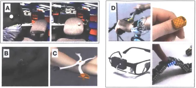
1-1 Inspirations for DWT. A) Parasitic mobility. Robots attached to the person, than to the chair. B) SkinSucka from Studio XO. A concept video with skin crawling robots. C) Nixie, a drone thats also a bracelet.
D) My previous research in wearables and robotics. . . . . 27
1-2 The overall system diagram of DWT robots. The arrows show the information flow between the subsystems. . . . . 29
2-1 Dynamic wearable technology (DWT) and related technologies. Ap-proximate body coverage of the technology in comparison to it's size. In my previous research and this thesis I explored the technologies highlighted in red. . . . . 34
2-2 Examples of state-of-the-art wearable devices. A) Epidermal electron-ics: microfabricated stretchable electronics. B) iskin, an on-skin elec-tronics using conductive ink. C) Apple watch with the green LED tuned on, which is used for measuring heartrate and blood oxygen level. 35
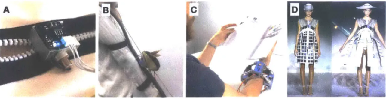
2-3 Explorations of moving wearable devices and clothing. A) Zipper-bot;
a robot that zips clothing. B) Daily support robots, a mouse-looking robot that moves on a rail. C) Movelet, a bracelet that moves up and down the arm for haptic applications. D) Hussein Chalayan fashion show with transforming clothing. . . . . 36
2-4 Examples of sensor suits and skins. A) Denum Jacket with capactive sensing conductive fibers. B) Body motion capture suit from Xsens. C) Pressure sensor skin from Takao Someya's group. D) LillyPad Arduino, a kit for wearable electronics. . . . . 37
3-1 Testing of two adhesives for repeated sticking and releasing on the skin. Linear fits are overlayed on the data. We tested a hydrogel and a sticky gel pad. The hydrogel worked for more adhesions than sticky gel pad, before losing adhesive properties. The release forces had large variations from sample to sample. The testing was conducted with a
20N force gauge, and peak force was recorded. . . . . 43
3-2 The iterative design process of SkinBot showing different prototypes. A) Rovables [1], cloth climbing robot. The initial designs were based
on Rovables platform. B) Prototype based on a wheel-leg climbing robot design in [2]. Tracks on the outside were used to synchronize the wheels. This prototype does not have enough contact area to adhere to the skin reliably. C) Similar wheel-leg design, but contains tracks on the inside. This design also does not have enough contact area. D) Prototype with sticky tracks. E) Initial suction-based robot with two servo motors that allows suction cups to extend and contract. We found that two motors are not enough for reliable movement, as the suction cups need to be pushed down to create a reliable seal. F) Current robot design, which is explained in detail in this paper. . . . . 43
3-3 Suction cup design for skin attachment. A) The cross section of the
suction cup CAD model. B) The vacuum pressure changes during the suction cup attachment and detachment. C) Snapshots of suction cup attachment to the skin. The pictured suction cups were made from clear 3D printed material. . . . . 44
3-4 Locomotion mechanism overview. A) Finite state machine diagram for the robot locomotion. The rounded rectangles and arrows represent the states and transitions, respectively. The red numbers next to the circles indicate specific states. The pressure sensors control the state machine. States 1 and 4 involved reattaching suction cups, which was done by moving the suction cup down in increments and checking the pressure each time. B) Pressure changes during the locomotion sequence, which was measured independently on the right and the left suction cups. The diagram also shows the corresponding states of the finite state machine on the top. C) Model representing physical locomotion. . . . . 47
3-5 The master circuit board image. This board contains all the
compo-nents required to run the tethered robot. The master board connected to the computer through the USB for communications and program-ming. The pumps, solenoids and servo motors run off separate power supply at 3.3V . . . . 47
3-6 SkinBot design. A) The system diagram of the main components of
SkinBot. B) Robot attached to the arm. C) The front of the robot. The robot combined four linear servo motors and a DC gear motor to allow translation and rotation. D) The side view of the robot. . . . . 48
3-7 An image of the soft robot prototype . . . . 48
3-8 Pneumatic control board for the soft robot . . . . 49
4-1 a) Multiple Rovables are climbing a shirt to show swarm abilities. b) close-up of one robot. . . . . 54 4-2 Illustration of the magnetic drive system. a) The fabric is held between
the top two wheels and magnetic rod on the other side. All the wheels are circular neodymium magnets. The reflective pattern on the wheels is used for the infrared encoder. b) Underside view of the chassis, with the fabric, removed. Two motors are visible in this view. . . . . 55
4-3 Picture of the electronics and sensors. a) Top view. The custom-designed circuit board is visible on the top. Infrared encoders are placed on the left and right wheels. The expansion port on the top is used to add more functionality. b) Side view. As visible in this view, the battery is sandwiched between the motors and the circuit board. 56
4-4 The wireless charging system. a) The receiver coil is mounted on the underside of the chassis. b) The yellow transmitter coil can be taped on the backside of the fabric. The Rovable is parked on the coil, as seen by its magnetic rod. The main body is on the other side of the fabric. . . . . 58
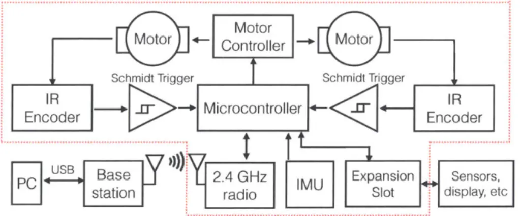
4-5 System diagram. The parts inside the red dashed lines are on the main board. ... . .. . ... . . .. . 58
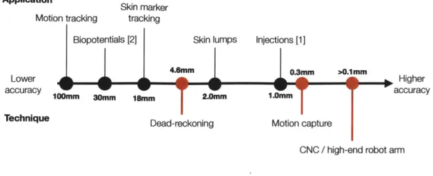
5-1 Accuracy required for different applications, and accuracy obtained
from different localization techniques. . . . . 62 5-2 The graphical representation of the dead-reckoning algorithm. The
location is determined by previous location, yaw angle, and the traveled distance. . . . . 67 5-3 Picture of the robot equiped with the camera . . . . 69
5-4 Temporary tattoo markers. a) Closeup of the marker. The fiduals and proximity markers are for the camera. The red placement guide is for initial robot placement. b) The marker as seen by the machine vision. 69 5-5 Guided attachment of the markers. a) The phone is used to guide the
placement. The cover of the marker has a sticker for visual rotation.
b) The marker is attached before the sticker is removed c) The cover
sticker is removed d) The robot is placed on the marker as the starting p oint. . . . . 70 5-6 Four infrared proximity sensors for active navigation markers. .... 71 5-7 Example of SkinBot localization with the dead-reckoning approach
5-8 SkinBot with four reflective markers for optical tracking . . . . 74
5-9 Localization accuracy on a 2D fabric. Comparison of a camera (ground
truth) and on-board sensors for localization of one path. . . . . 75 5-10 Fabric test bed used to develop the navigation and control algorithms 76 5-11 Localization of the robot on a fabric in 3D space. . . . . 77 5-12 Using two birthmarks on the forearm for navigation. a) Picture of
the two birthmarks that were used. b) The birthmarks as seen by the machine vision. c) The threshold applied by the machine vision algorithm to find the birthmarks. . . . . 78 5-13 Using two birthmarks on the forearm for navigation. a) Picture of
the two birthmarks that were used. b) The birthmarks as seen by the machine vision c) The threshold applied by the machine vision algorithm to find the birthmarks. . . . . 79
6-1 A) Clothboth climbing on a shirt using gripper wheels. b) CLASH robot. 84 6-2 Skin attachment experiments. A) Maximum adhesion forces with
dif-ferent suction cup diameters as indicated by force at release. B) Pres-ence of hair on the skin reduces the maximum adhesion force. C) Di-agram illustrating the vertical displacement of the skin under suction. The suction cup of 6mm and 18mm diameters are shown in the illus-tration. The 6mm diameter cup creates a better cup-skin seal, as it has a larger seal area... 86 6-3 Robot locomotion on the arm. SkinBot climbing on the arm during
100 seconds. . . . . 88
6-4 Attachment to a curved skin. A) Robot attachment to a cylindrical surface with a 2.5cm radius. Left: robot before it engages the vertical servo motor to push the suction cup down. Right: suction cup displaces the skin by about 2.7mm, which is not enough to make a reliable cup-skin seal. B) Robot attachment to a cylindrical surface with a 12.5cm radius. In this case, a reliable cup-skin seal is created. . . . . 89
6-5 Rotation of the robot due to sagging of the skin. A) Free force diagram
of the robot in a vertical position. One foot is detached, as the robot is taking a step. B) An example scenario where the robot is rotated into a position that does not allow attachment. This is caused by sagging of the skin caused by torque (Mki) on the skin, due to the weight of the robot. C) The experimental data from three locations on the arm. The data shows the relationship between the robot rotation angle
(Orobot - 6sin) and its weight. Linear fitting lines are shown. ... 90
6-6 The after effect of the suction cups on the skin. The Y-axis is the
duration the suction cup was applied to the skin. The snapshots are shown at different time intervals after the suction cup was removed. For example, when the suction cup was applied for 5 sec, no visible marks remained after 10 seconds. . . . . 92 6-7 Measurement of attraction (top) and climbing forces (bottom) on
dif-ferent fabrics. . . . . 94
7-1 Power consumption during the adhesion experiment. A) The power consumption of the pumps required to keep the robot attached to the skin at different vacuum pressures. The pumps were duty cycled by turning on only when vacuum goes under a certain threshold. Overall, the power consumption is an order of magnitude lower than running pumps continuously at 1076mW. B) Sample pressure data showing duty cycling of the pressure to keep the pressure at the threshold of -25kP a.. . . . . 97 7-2 A) Circuit board and B) assembled untethered prototype of SkinBot . 98
8-1 Comparison of different compoments sizes that can be used for pneu-matics in epidermal robots. Left to right: solenoid, pressure sensor, piezoelectric pump, piezoelectric blower, diaphram pump with DC mo-tor . ... ... . ... .. . . ... . . .... .105
9-1 The Epidermal Eobot equiped with a plunger to test mechanical prop-erties of the skin. In this picture, the robot is attached to forearm. . . 110 9-2 Stress vs. strain graph obtained from pushing the skin on the arm.
The red line is the slope, which was used to obtain Young's modulus. 112
9-3 3D printed arm brace with different stiffness segments. . . . . 112 9-4 Infrared proximity sensor integrated into the suction cup of the robot. 113
9-5 Displacement of the silicone during suction, as measured by the
in-frared proximity sensor inside the suction cup . . . . 114
9-6 Cutometer sensor measures tissue displacement in the suction cup. The lump will change tissue properties and thus, infrared reflectance. . . . 115
9-7 Heat map (Bessel fitting) generated by measuring displacement in a
simulated tissue lump in locations 5mm apart. Grid of different lump depths and lump diameters are shown. "No ball" heat map did not contain a lum p. . . . . 115 9-8 The biopotentials pickup circuit diagram. EMG and EKG had the
same analog front end: instrumentation amplifier with a gain of 10. The amplifier was followed by a high pass filter of 0.16 Hz, which removed the DC baseline. To capture the complete signal shapes, the circuit was referenced to 1.65V (half of the supply). . . . . 116 9-9 Biopotential sensing: A), Electromyographic signal measured on the
upper arm when closing the hand. B), Electrocardiographic (EKG) signal measured on the chest showing the QRS complex, C), Electro-dermal activity signals on the wrist in response to an auditory stimulus.
D), Side view of SkinBot showing the modified suction-cups to monitor the electrical properties of the skin. Visual Imaging (middle row): . . 117
9-10 Visual imaging of the skin. a) Bottom view of the robot showing the
camera sensing module. b) Epidermal robot using the camera module with a white LED for illumination. c) Camera snapshot showing a birthmark and d) Snapshot showing hair. . . . . 118
9-11 Inertial sensing with Epidermal Robot: A) changes in accelerometer
data during sitting and lying down position captured on the chest, and B), cardiorespiratory motions captured on the chest. C), IMU board mounted on the robot. The backside of the IMU board contains a microcontroller (MCU) and a radio. IMU board also provides a
connector to attach different modules such as an EKG module. . . . 119
9-12 Using Rovables for motion capture. a) Rovables move to the right
posi-tion on the arm. b) The kinematics of the arm is reconstructed on the screen. With more Rovables whole body skeleton can be reconstructed. 120
9-13 Wearable displays application. a) and b) The displays link together
with magnets to form a larger name tag. c) The display can travel to the wrist to form a watch. d) The backside of the display shield exposes the IR beacon system and magnets for alignment with other displays. e) The Rovable with the attached display shield . . . . 122 9-14 Tactile feedback application. We designed a linear actuator that can
poke the skin. This tactor can go up and down to create tactile feedback.123
9-15 Shape changing fabric. Robot self-attache to fabric shifts to become a
scarf according to temperature change. . . . . 123 9-16 Interactive moving jewelry. Robotic brooch moves to become a
shoul-der microphone speaker when wearer recieves a phone call. . . . . . 124
12-1 Skinbot control board . . . . 138
12-2 Rovables main board. . . . . 139 12-3 Infrared encoder board schematic for Rovables . . . . 140 12-4 PCB Gerber of the wheel encoder pattern. . . . . 141
12-5 PCB Gerber of the wheel encoder board . . . . 142
12-6 Flexible PCB of the custon cable between the encoder and the Rovables
m ain board. . . . . 143
12-7 Schematic of one module for the soft robot control board . . . . 144
List of Tables
1.1 Selected specification of the two designed robots. . . . . 26
5.1 Summary comparison of studied localization methods. The colors
in-dicate if the specification satisfies DWT requirements. Green color is acceptable and red color is not. . . . . 66 5.2 The table provides comaprison between the on-board navigation
sys-tems and using external optical motion capture system. In some cases an optical motion capture system can be used instead of dead-reckoning.
. . . . 7 3 7.1 Table showing current consumption of different robot subsystems. . . 100
8.1 Table showing minimum sizes and weights of different components.
Chapter 1
Introduction
Recently there have been great advances in wearable electronics. In parallel, there are rapid improvements in machine learning [3, 4], mainly driven by an increased amount of collected data, improved algorithms and computing power, as governed by Moore's law'. The machine learning approaches are useful in finding patterns in complex data such as physiological signals.
To leverage the advantages of computing power, we need to find better ways to collect data on our bodies systematically. Supervised learning algorithms require repeatable, quantitative, and labeled data. Robots are well suited for such data collection task. As evident by the smartwatches domination of the wearable sensor market [5], the current paradigm of wearable sensors enables us to collect data or actuate just from one location. Furthermore, they require manual manipulation and placement. Almost for all wearable sensors, their position plays a significant role. If we look at nature for inspiration, we find that a healthy ecosystem has static (e.g., forests) and dynamic organisms such as animals and insects. The digital ecosystem around our bodies has only static devices, severely limiting its functionality.
This thesis proposes and explores wearable devices that move autonomously on the human body as mini-robots. We named this idea Dynamic Wearable Technology
(DWT). Specifically, the thesis introduces two complementary robots: Epidermal Robots that can move on the skin, and the Rovables that move on the clothing. The
specification of the two robots are summarized in Table 1.1.
Robotics is a relatively new field, with the first industrial robots appearing in the early 1960s [6]. As a result, there is not much crucial historical context. Minia-ture robots require sophisticated electronics with low power consumption and MEMS fabrication. Such robots have only become accessible in recent years, due to improve-ments in microfabrication. On the other hand, living creatures were used on the human body for a long time. For example, in Mexico and ancient Egypt, a beetle on a chain was used as jewelry [7]. Maggots are used for chronic diabetic ulcers [8] and leeches have been used for medical purposes for more than 2500 years
[9].
lmm
Om
ROVables
Epidermal Robots
Movement mechanism Magnetic wheels Suction cups
Movement surface Fabric Skin
Weight 20 grams 20 grams
Size 2.6 x 3.6 x 4 cm 2.7 x 2.0 x 4.2 cm
Power source 100 mAh battery Tether
Untethered yes, wireless no
Mechanism 2 geared motors 4 linear motors, 2pumps1 gear motor,
Controller ARM Cortex MO ARM Cortex M4F
Sensors 2 wheel encoders, IMU IMU
Table 1.1: Selected specification of the two designed robots.
There are three inspirations for this work. First, the Nixie bracelet drone [10] from
-A
DT
B%
VaFigure 1-1: Inspirations for DWT. A) Parasitic mobility. Robots attached to the person, than to the chair. B) SkinSucka from Studio XO. A concept video with skin crawling robots. C) Nixie, a drone thats also a bracelet. D) My previous research in wearables and robotics.
2014 Intel Make it Wearable contest, led me to believe that wearable technology does not need to be static. Second, a concept of parasitic mobility [11] was developed in
2005 in our research group: Responsive Environments at the MIT Media Lab. This
concept showed sensor nodes that can hitchhike on a person, and detach where they are needed. Third, the previous work I did in medical imaging [12, 13] , wearables [14,
15] and robotics [16, 1]. Doing those projects allowed me to understand the limitations
of the current technologies and build up the technical skill required for this thesis. Those three ideas lead to the Rovables project.
We explored using Rovables as a platform for Human-Computer Interactions (HCI) and fashion applications. For example, we used Rovables to provide local-ized tactile feedback and as a moving fashion accessory. For such applications, the untethered ability to move on clothing worked well. As a disadvantage, the Rovables did not make skin contact.
Skin contact is required for almost all physiological sensing and medical appli-cations, and I was interested in exploring such applications. Furthermore, I was interested in the technical challenge of designing the robots that climb the skin, as
it has not been done before. This lead to the development of the SkinBot and the area of Epidermal Robots. Among some applications, we use the robot to detect and classify lumps under the skin. Concept video [17] from a design firm Studio XO had demonstrated the idea of Epidermal Robots well, a few years before we started such development. In the video, swarms of small robots moved around the body and applied makeup.
Such small climbing robots could be used for other purposes than wearable devices. For example, they could be used for finding cracks in an airplane engine or scale mountain terrain. General climbing robots has been explored in robotics field in great detail before (e.g., [18, 19]). This thesis examines only wearable applications to avoid broad but shallow exploration of this topic. Also, I believe that the blend of wearable electronics and robotics is a new area of research.
1.1
Dynamic wearable technology (DWT)
In this section, we attempt to outline the main design criteria of DWT robots. Each of those criteria is discussed in separate chapters in the thesis. To satisfy those criteria, the system design of the DWT robot needs certain subsystems. In Figure 1-2 we provide a block diagram of a DWT robot.
" Small size (chapter 8). The robots should be well below an order of
mag-nitude smaller than the human body, millimeters to few centimeters in size. First, small robots are less obtrusive to the human host. Second, it is easier for a small robot to move around a complex surface such as the human body. Coarsely, the human body can be thought of as cylindrical. surfaces [20]. To a robot that is an order of magnitude smaller, such surfaces will appear flat.
" Ability to move freely (chapter 6). The robots should have the ability to
move freely on human clothing or skin. They should be able to move vertically as well.
body on their own. Navigation requires a localization method and a map. The robot operation should not require any external sensors or devices.
• Platform (chapter 9). DWT should be able to support different types of sensors or actuators, to allow the development of different applications.
Motion sensors
4************
Figure 1-2: The overall system diagram of DWT robots. The arrows show the infor-mation flow between the subsystems.
1.2
Why is DWT important
Let's imagine a future scenario where we already have small robots that fulfill the previous requirements. Medicine is becoming more personalized and data-driven and will continue to do so in the future [21]. Potentially, DWT will become our first
Electronics
Body
FNMEEOM RA- .I
I
line of defense against diseases. To do a yearly medical check, instead of going to a doctor or a hospital, one would order online a personalized box of robots, tailored for a specific purpose. After receiving the robots, the person would put the robots on, perhaps while going on through an everyday routine or sleeping during the night. The robots will take repeatable and high-resolution measurements of the body. The robots could see things that are impossible for a doctor to see with a naked eye. For example, robots can test the mechanical properties of the skin to detect very early signs of cancers. All the data is collected and analyzed with powerful computers remotely. If the robots discover something, they could use a precise laser to remove the problematic skin cells. Also, the robots can see invisible signals of the body, such as bioelectrical potentials (EKG and EMG). Once the robots finish, they can be shipped back, just like returns in online shopping.
DWT can be used in many fields, such as medical sensors, human-computer in-teractions, body-care, arts, and fashion. I will provide specific example applications throughout the thesis. Currently, I believe the most productive use is medical sens-ing, as it can have an immediate improvement in our lives. Chapter 2 (Background) provides a thorough comparison to other technologies. Below, I will attempt to sum-marize the benefits of DWT. All DWT robots have the following characteristics.
" Continous and repeatable measurements. The robots eliminate errors and
uncertainties associated with human operators.
* Variable and accurate spatial resolution As the robot can adjust their step
size, they can sample with both high and low resolution. This allows robots to obtain 2D and 3D data.
•
Full-body coverage. The robots can access any location on the body.* Easy to transport The small and lightweight robots are easy to transport to
a remote location or home. This is a great benefit for individuals with limited mobility or in remote locations with no access to sophisticated instruments.
by another person. Robots can potentially provide complete privacy.
Depending on the applications, the robots might have additional benefits:
" Ability to work in swarm. The robots could work together to coordinate
tasks to accomplish them faster or to create sensor arrays. For example, one robot could serve as a transmitter and other as a receiver.
" Sophisticated sensors and actuators. The robots are not limited to
sim-ple sensors, as many current wearables. As a payload, the robots can carry sophisticated sensors, such as cameras.
1.3
Chapter and thesis summaries
The thesis has four main parts: The first part (Chapters 1,2) provides an overview of DWT, as well as describes previous work and technologies. A second part (Chapters
3,4) dives deep into the implementation of Epidermal Robots and Rovables. This part
is primarily based on my previously published work on this topic [1, 22, 23, 24]. The third part (Chapters 5,6,7,8) provides a discussion of the main design criteria of DWT, such as power consumption, navigation, climbing, and size. The fourth part (Chapters 9,10,11) discusses applications of DWT, as well as limitations, future work, and concluding remarks.
1.4
Contributions of the thesis
This thesis makes the following contribution:
1. We introduce a new area of Dynamic Wearable Technology.
2. As two instances of DWT, we develop Epidermal Robots and Rovables. Epi-dermal robots can move on the surface of the skin. Rovables can move on the clothing. All the design files and instructions are open-sourced online on Github2
3. We discuss and study various points of DWT such as power consumption, size,
and localization.
4. We showcase various applications of DWT in medicine, human-computer inter-actions, and art domains.
Chapter 2
Background
In this chapter, DWT is positioned against existing technologies. Since DWT is a blend of robotics and wearable electronics, backgrounds for both fields will be provided. Figure 2-4 summarizes complex relationships between DTW and other technologies. This chapter will look into each technology in the graph in detail, and discuss their advantages and disadvantages. This graph demonstrates the unique and unexplored space that DWT occupies. By looking at the graph, DWT provides variable body coverage while maintaining the size of wearable devices.
2.1
Wearable Electronics
Wearables first appeared in the early 1960s. The first instance of wearable technology appeared in 1961 as an electric device hidden in the shoe to improve gains at a game of roulette [25]. Another example of an early wearable device from the late 1960s is a spacesuit, which contains a portable life support system. (e.g., Apollo 15-17 EMU) The idea of wearable technology was explored and popularized by Thad Starner and Steve Mann at the MIT Media Lab, with untethered wearable cameras and head-mounted display [26].
Today due to electronics miniaturization, many wearables have reached the con-sumer market. For example, smartwatches are popular. They can provide easily accessible information, as well as sense activity, and provide limited physiological
*Dynamic wearable technology Inside body robots DWT* Ex Wea Wearbles Surgical robots MRVCT scanners Whole body -0h 0 One Location um mm cm Size of device meter
Figure 2-1: Dynamic wearable technology (DWT) and related technologies. Approx-imate body coverage of the technology in comparison to it's size. In my previous research and this thesis I explored the technologies highlighted in red.
signals such as heart rate using photoplethysmogram (PPG) with near-infrared spec-trometry [27]. Research in Human-Computer Interactions (HCI) has explored many aspects of smartwatches. For example, using motors to provide haptic feedback [28] or to move the watch [29]. Also, researchers explored additional sensing such as electric field [30] on a watch form factor. Today the cutting edge wearable devices research are stretchable tattoo-like epidermal electronics, which have been pioneered by the Rogers group at Urbana Champaign [31]. Also, starting with iSkin [32], multiple projects [33, 34] in human-computer interactions demonstrated tattoo-like wearables. Wearable devices, including commercial examples and state-of-art research proto-types, are designed to be fixed in one location to perform a specific function. Even though they can vary in size from millimeters to centimeters, wearables cover single point coverage.
However, there are a few exceptions, where researchers and designers looked at moving wearable devices. In a Ph.D. thesis from MIT Media Lab, Zipperbot [35]
)skeletons
rable robots Nano
A
7 F
Figure 2-2: Examples of state-of-the-art wearable devices. A) Epidermal electronics: microfabricated stretchable electronics. B) iskin, an on-skin electronics using conduc-tive ink. C) Apple watch with the green LED tuned on, which is used for measuring heartrate and blood oxygen level.
attaches to a zipper and can zip and unzip clothing. Other robots did not climb directly on the clothing but demonstrated cloth climbing ideas. The concept of Daily Support Robots [36] showed a robot that moves on the body to provide notifications, using a rail on the arm for climbing. It is one of the earliest examples of moving wearables in the Human-Computer Interaction field. Movelet is an arm brace that can move up and down, providing haptic feedback [37].
Fashion designer Hussein Chalayan has done multiple fashion shows with trans-forming clothing [38], where motors and pulleys were used to move the dresses. Behnaz Farahi designed a 3D-printed garment that moves based on other peoples gazes [39]. Other designers showed fabrics that can change shape, such as using magnets embedded inside the fabric [40].
2.2
Sensor fabrics and materials
A brute force approach to increase body coverage of sensors is to increase the number
of sensors. With this approach, the coverage is directly proportional to the number of sensors. The common approach is using e-textiles, where electronics are integrated into the fabric. This was investigated early at the MIT Media Lab [41] with embroi-dery of conductive threads. A research community sprung up around this area, cre-ating many new fibers, techniques, and applications for sensate garments [42, 43, 44].
-- -~ - I
A BD
Figure 2-3: Explorations of moving wearable devices and clothing. A) Zipper-bot; a robot that zips clothing. B) Daily support robots, a mouse-looking robot that
moves on a rail. C) Movelet, a bracelet that moves up and down the arm for haptic
applications. D) Hussein Chalayan fashion show with transforming clothing.
E-textile were further popularized by Leah Buechley with an introduction of
Lily-Pad kit, which made it easier to create e-textiles [45] using friendly form factor and
the Arduino platform. This approach has been investigated by Google ATAP
re-cently commercialized jackets with capacitive sensing for gestures [46]. A state of the art approach is to integrate semiconductors into textile fibers [47] directly. Some approaches do not require the sensors to be embedded in the fabric. For example,
placing 17 inertial measurement units (IMUs) in pre-defined body locations allows for
full 3d body tracking [48]. In this approach, a suit is used to ensure that the sensors
always stay in the same place. Another approach is to create flexible sensor skins with various sensors, instead of integrating electronics into the fabrics. For example,
Takao Someya's group at the University of Tokyo demonstrated a flexible pressure
sensor array for robotic applications [49]. As a precedent to DWT, we demonstrated
SensorTape, a dense sensor network distributed along a length of a flexible tape-like
circuit board. It could be used as a wearable sensor skin to track posture, as well as
be cut to different sizes [50].
There are multiple disadvantages to using sensor-laden materials. First, they
require custom fitting fabrics to ensure good contact with the skin. Second, there is a scaling problem with an increasing number of sensors. The size, complexity, price, and power consumption increases with the area coverage. It is not a huge issue for simple sensors such as electrodes but becomes a problem with multiple complex sensors such
as cameras. Third, the spatial resolution is limited by the physical sensor layout. This could be a disadvantage in applications where a variable or custom resolution is required. For example, different areas might require distinct resolutions or resolution could be adapted based on collected data. Nevertheless, this approach is promising. With the improvements in electronics size and power, we can integrate more and more sensors into clothing.
A BP
Figure 2-4: Examples of sensor suits and skins. A) Denum Jacket with capactive sensing conductive fibers. B) Body motion capture suit from Xsens. C) Pressure sensor skin from Takao Someya's group. D) LillyPad Arduino, a kit for wearable electronics.
2.3
Micro and nano robots
Nanorobots and microrobots that go inside the body is an area of active research. The advantage of microrobots is that they can be non-invasively injected into the body. There are significant challenges to realizing this, such as power and size, so off-the-shelf technology cannot be used. There have been robots proposed to move inside blood vessels [51]. Many microrobots are steered by external magnetic fields [52]. Some exciting work has focused on how a swarm of robots can be inserted through a needle and assembled inside the eye [53]. Some biomedical microbots were actuated
by shape memory alloy wires [54] or vibrations [55].
The main disadvantage of micro/nanorobot is its limited functionality. It is not yet technically possible to integrate computing and energy sources into such robots, so they lack autonomy. Usually, they are driven by an external machine, so the person
remains tethered to a specific location.
2.4
Mini-robots inside the body
The mini-robots also go inside the human body but are larger than the nano and microrobots. They are usually at a millimeter to a centimeter scale. At this size, they can potentially be autonomous, as they can contain computing and a power source. There are task-specific medical prototype robots, such as a small bone-mounting robot for spine surgery [56], a snake-like robot that goes into the airways [57], and an endoscope robot to look inside the body cavities [58]. Most relevant to DWT is HeartLander [59, 60], Carnegie Mellon's robot that uses suction to locomote on the surface of the heart and deliver injections. This robot has been tested on a beating
pig heart. The robot was developed in the early to mid-2000s and appeared to be in
the commercialization stage since.
The disadvantage of mini-robots is that they are invasive. Such robots are too large, so they require an invasive entry into the body. DWT is on the same size scale, but it is not invasive.
2.5
Room-size devices
Full body coverage can be achieved by putting the person inside a large machine or having a large robot with a long reach. Typically, a large machine such as a CT or MRI scanner is used. Another approach is using non-contact sensing, such as radio signals [61] or cameras [62] to sense heart rate and respiration.
Some surgical robots are already being used in medicine. There are large robots that can perform surgery with teleoperation. There are two main such robots: the research robot Raven [63] and commercial Da Vinci robot [64].
The main disadvantage of large machines is that the person requires to be enclosed
by the device or remain in a specific location, so this approach can not be used in an
2.6
Exoskeletons
Currently, the term wearable robots refer to exoskeletons. Exoskeleton's role is to improve or restore human abilities. Some can be purely medical, such as an active prosthesis, for example, an artificial hand controlled by EMG signals [65] or an active leg prosthesis [66]. The applications of such robots are straightforward: to restore the function of a missing or damaged limb. The second application of exoskeletons is to improve abilities or to add haptics. For example, an upper arm exoskeleton was de-veloped by Columbia University [67]. Other researchers made additional appendages such as fingers [68] or arms [69]
2.7
Chapter Summary
In this section, various technologies regarding body coverage and size were presented. There are advantages and disadvantages to each technology. DWT occupies a unique niche in this space. As seen in the Graph 2-4 DWT can provide variable coverage at the size of a small wearable device. Also, we found that the small on-body robots have not been extensively explored before, and this provides a lot of opportunities for future exploration
Chapter 3
Epidermal Robots
This chapter describes the design and manufacturing of Epidermal Robots. Also, it attempts to rationalize the design decisions of the robot. The first functional Epidermal Robot is called SkinBot, and is the main focus of this chapter. In the future, Epidermal Robots should be made from soft materials, so they match the elasticity of the skin and are more resilient. The soft robotics prototype is briefly described at the end of the chapter.
3.1
Introduction
To perform their tasks successfully, Epidermal Robots need to meet several specific requirements. First, the robots need to be lightweight and small (under 80 grams and centimeter-sized according to our experiments) to minimally disrupt the person while exploring the different parts of the body. The weight requirement was exper-imentally determined in chapter 6. Second, Epidermal Robots need to have direct
access to the skin. Human skin is not only the largest organ of the human body
but also offers a good proxy to capture relevant information about the skin (e.g., appearance, texture) and inner body responses such as physiological signals (e.g., electrocardiograms, electrodermal activity). Third, the robot needs the ability to
adhere and locomote over the non-uniform skin, which contains many
to different robot orientations. Fourth, Epidermal Robots should offer multimodal sensing. The human body contains a large range of information that requires dif-ferent types of sensing modalities. To ensure the robot can successfully digitize the human body, the sensing module should contain as many sensors as possible, while still satisfying the previous considerations. Finally, Epidermal Robots should have the ability of accurate self-localization on the body (under 18 mm error rate, due to the camera's field of view, detailed in Chapter 5), which is key for autonomous operation and mapping of the human body.
3.2
Implementation
For reference and reproduction, all the design files and software can be found in an online repository.
3.2.1
Skin Adhesion
Human skin has complex mechanical behavior and is elastic at small loads. In partic-ular, it has Young's modulus 2 ranges from about 0.1MPa to 1.1MPa [70], with a high
dependence on the test subject's age, the analytical model, and the measurement in-strument [71]. Also, the human body has some degree of curvature and features such as hair which makes adhesion even more challenging. Since skin is a complex surface, we conduct in vivo experiments as much as possible. However, in some cases such as testing specific skin curvature, we perform experiments on artificial skin created with silicone (Ecoflex 00-30, Smooth-On)3 which has a similar Young's modulus as
the skin.
We designed and built a total of six robot prototypes that considered different locomotion systems (Fig. 3-2). On the one hand, some adhesion approaches such as pinching the skin were not practical and were excluded from the start. On the
lhttps://github.com/adementyev/SkinBot
2
Young modulus is a measure of material's stiffness. Young modulus is defined by the relation between strain and stress
3
-1
120 i 1
10- sticky gel pad fit
100hydrogel fit
CD) - -sticky gel pad
(80 hydrogel 60 00 .9? 40 a) 20 -0 0 20 40 60 80 100 120 140 160 180 200 Adhesion attempts
Figure 3-1: Testing of two adhesives for repeated sticking and releasing on the skin. Linear fits are overlayed on the data. We tested a hydrogel and a sticky gel pad. The hydrogel worked for more adhesions than sticky gel pad, before losing adhesive properties. The release forces had large variations from sample to sample. The testing was conducted with a 20N force gauge, and peak force was recorded.
Figure 3-2: The iterative design process of SkinBot showing different prototypes.
A) Rovables [1], cloth climbing robot. The initial designs were based on Rovables
platform. B) Prototype based on a wheel-leg climbing robot design in [2]. Tracks on the outside were used to synchronize the wheels. This prototype does not have enough contact area to adhere to the skin reliably. C) Similar wheel-leg design, but contains tracks on the inside. This design also does not have enough contact area. D) Prototype with sticky tracks. E) Initial suction-based robot with two servo motors that allows suction cups to extend and contract. We found that two motors are not enough for reliable movement, as the suction cups need to be pushed down to create a reliable seal. F) Current robot design, which is explained in detail in this paper.
other hand, adhesive wheels and tracks did not provide consistent adhesion force. For instance, the adhesive force of two commercial adhesives (Katecho and Premium Fixate Cell Pads, CloudValley) decreased with each peel by about half a percent (Fig. 3-1) while having significant variations between peels. With the continuous attachment and detachment cycles, required for locomotion, the adhesive force quickly
degrades. Also, the hydrogel adhesive picks up dirt, oil, and dead epithelial from the skin, thus requiring periodic cleaning. After considering different methods, we finally selected a suction-based approach which was inspired by living organisms such as leeches and cephalopods (e.g., squid, octopus).
In suction-based locomotion, a suction force appears when a lower pressure is created inside a cup, and the pushing of the atmospheric pressure causes an adhesion force. While suction cups used in the industrial applications are usually made of soft rubber, we found that rigid cups can be used with the skin. Under vacuum, the flexible skin gets pulled into the cup to seal the skin-cup interface (shown in Fig. 3-3C). While rigid suction cups can be quickly prototyped with a standard 3D printer, flexible suction cups require a multi-part silicone mold. We found that the bell-shaped cup worked well with the skin. The bell provided a large inside volume, into which the skin can expand. A similar bell design is often used in cupping therapy, alternative medicine in which suction cups are applied to reduce pain and swelling.
A
B
O"'°"
0 10 20 30 40
Time (sec)
C
O rM 290ms 373ms
Figure 3-3: Suction cup design for skin attachment. A) The cross section of the suction cup CAD model. B) The vacuum pressure changes during the suction cup attachment and detachment. C) Snapshots of suction cup attachment to the skin. The pictured suction cups were made from clear 3D printed material.
The final implementation of SkinBot uses two 9mm-diameter suction cups. To make the suction cups as well as all other mechanical parts, we used a 3D printer (Form 2, Formlabs, gray resin). The 9mm suction cup provided the best
size-to-adhesion-force tradeoff and is analyzed in more detail in Chapter 6. This configuration provided a maximum of 200gf (gram-force) adhesion force, which is enough to hold the 20-gram SkinBot securely. The minimum vacuum pressure required for skin adhesion was measured to be about -10kPa. However, we pull the maximum vacuum of -30kPa using a small membrane diaphragm pump (SC3101PM, Skookum Electronic co.). This pressure was determined by the construction of the pump, specifically by the piston displacement volume. When the vacuum pump is turned off, due to leakage, the pressure slowly returns to atmospheric pressure. To speed up this process, we added a solenoid valve (S070C-SDG-32, SMC Pneumatics) that vents the vacuum line. Using a diaphragm pump also has some problems such as the loudness (55 dB at 30cm) and the large size (32x8x18mm). We also considered piezoelectric pumps, but current commercial models (e.g., mp5, Servoflo) only provide a maximum of -10kPa which does not leave any safety factor for air leaks, hair and pump variations that can make adhesion less reliable.
3.2.2
Skin Locomotion
We wanted to achieve locomotion with the ability to turn with a minimum number of motors as they are one of the largest components. The selected gait was inspired
by an inchworm mechanism where climbing is achieved by creating an anchor point
and pushing the body away from that point. At a minimum, this motion requires one actuator to extend and contract the robot's body. In our case, however, we used two linear servo motors to extend and contract the body to allow independent left and right side control. In particular, we used linear servo motors (SPMSA2005, Spektrum) with a 9.1mm throw, commonly used in small radio-controlled airplanes that can pull 100gf (gram-force) and weight around 1.8 grams. Furthermore, at least two independent anchor points are required, which can be detached and attached on demand. Thus, two independent pumps and suction cups were used to provide controllable attachment. Also, we added two of the same linear motors to move the suction cups up and down. This prevented dragging of the end effector during extension and contraction and gave the robot the ability to attach to non-uniform
surfaces. Finally, we added a planetary gear motor (TGPP06-D-136, TT Motor) and a motor controller (DRV8835, Texas Instruments) to add turning ability around one of the suction cups.
One of the critical challenges with skin locomotion is to ensure reliable adhesion at the new end-effector position. To address this, we added an air pressure sensor (MPXV611, NXP) in each of the vacuum lines to detect if the suction cup is attached. The pressure data were collected at 100Hz and filtered by a moving average of 20 samples to remove oscillations of the pump. The attachment was insured by moving the suction cup down in small increments and checking for adhesion each time. The whole locomotion was controlled by a finite state machine with 6 states and was implemented on an ARM Cortex M3 microcontroller (Teensy 3.6, PJRC). As shown in Fig. 3-4A, the transitions of the state machine were controlled by the pressure sensors. We conducted the testing using a tethered prototype, which contained valves, pumps, power, and control electronics on a separate master board, shown in Fig. 3-5. The overall system architecture is shown in Fig. 4-5A.
3.3
Soft epidermal robots
This section briefly describes the current and future direction of the soft Rpidermal Robot. We found multiple problems with the current rigid robot design. The rigid robot has limited degrees of freedom, which limits its reach around tight curvatures. Also, the robot would break if it gets squished, which can happen if a person rolls over during sleep. To have multiple degrees of freedom as well as a resilient structure, we created a prototype of a soft Epidermal Robot. Soft robotics has become a popular research topic and has a promising future, especially for robots that are near humans.
I initially became involved in soft robotics as we looked at how to integrate air