A Digital Answering Machine Using Analog
Caller ID
by
Fred D. Quintana
Submitted to the Department of Electrical Engineering and
Computer Science
in partial fulfillment of the requirements for the degree of
Bachelor of Science in Computer Science and Engineering
at the
MASSACHUSETTS INSTITUTE OF TECHNOLOGY
May 1993
@ Fred D. Quintana, MCMXCIII. All rights reserved.
The author hereby grants to MIT permission to reproduce and to
distribute copies
of this thesis document in whole or in part, and to grant others the
right to do so.
Author ... . ...
Department of Electrica, Engineering and Computer Science
May 17, 1993
Certified by... .. ...Gregory M. Papadopoulos
Assistant Professor
Thesis Supervisor
A ccepted by ...
Leonard A. Gould
Chairman, Departmental Committee on Undergraduate Theses
MASSACHUSETTS INSTITUTE
OF TECHNOLOGY
ARCHIVES
'JUL
2 6 1993
LIBRARESA Digital Answering Machine Using Analog Caller ID
by
Fred D. Quintana
Submitted to the Department of Electrical Engineering and Computer Science on May 17, 1993, in partial fulfillment of the
requirements for the degree of
Bachelor of Science in Computer Science and Engineering
Abstract
The purpose of this thesis is to build an answering machine that combines the speed and convenience of a digital answering machine with the advanced features of Caller ID to provide the telephone user with a level of control never before found in the home. On phone lines equipped with the Caller ID service, the phone number of the caller is encoded and sent out by the phone company. This information is sent between the first and second ring and can be retrieved to provide the callee with the caller's phone number. The device described in this thesis contains an internal database of phone number/name pairs which is scanned for a match as soon as the information becomes available. If the number is found in the database, the corresponding name is displayed on an LCD display; otherwise, the number is displayed. This feature saves the user from having to remember the numbers of frequently calling parties. This database can be updated using the telephone keypad. A log that contains all incoming and outgoing calls is also maintained. As a result, the user will know who called throughout the day, even if the caller does not leave a message on the answering machine.
The other component of this device is the integration of a digital answering ma-chine with the Caller ID decoder. This makes possible specialized outgoing messages, depending on who is calling. For example, you can assign one greeting to your boss, another to your parents, and yet another to your friend. This combination of a digital answering machine and Caller ID makes possible new and discrete ways of screening calls. There is no longer any need to wait for the answering machine to pick up in order to determine who is calling. When the answering machine answers, the appro-priate greeting will be sent. Since the device knows who is calling, it can also know how to act on that call.
Thesis Supervisor: Gregory M. Papadopoulos Title: Assistant Professor
Contents
1 Introduction 6
1.1 M otivations . . . 6
1.2 G oal . . . ... . . 7
1.3 Solution . . . . . . . ... .. 8
1.3.1 The Motorola 68HC16 Evaluation Board . ... 8
1.3.2 The Motorola Caller ID Receiver . ... 9
1.3.3 The AT&T Telephone Answering Device (TAD) Chipset . . . 10
2 Development Environment 13 3 Functional Specification 15 3.1 Full Specification ... 15
3.1.1 Mode 1: W ait for Call ... 17
3.1.2 Mode 2: Display Incoming Number . ... 17
3.1.3 Mode 3: Display Outgoing Number . ... 18
3.1.4 Mode 4: Browse Log ... 18
3.1.5 Mode 5: Play Announcement/Record Message ... . 19
3.1.6 Mode 6: Set Time ... 19
3.1.7 Mode 7: Modify Announcements . ... 20
3.1.8 Mode 8: Playback Messages ... 21
3.1.9 Mode 9: Administer Announcement/Number Database . . . . 22
3.1.10 Mode 10: Administer Name/Number Database . ... 22
3.1.12 Mode 12: Name Entry Mode ... 24
3.2 Current Implementation ... .... 24
4 Hardware Specification 26 4.1 The 68HC16 Evaluation Board ... .. 26
4.2 The Motorola Caller ID Receiver . . . . .. . . . . 27
4.3 The DTMF Touch-Tone Decoder ... 27
4.4 The LCD Display . . . . ... . . ... . .. . . .. . . . .. . . . . 28
4.5 The Analog Phone-line Interface . . . . ... .. 29
5 Software Specification 30 5.1 GPIP pins ... ... ... ... 30
5.2 The DTMF Receiver ... ... ... .. 30
5.3 LCD Display ... ... ... 31
5.4 CID Receiver ... .... ... 32
5.5 Touch-Tone Data Input ... .. 33
5.6 Clock Maintenance ... 33
5.7 Main Dispatch Routine ... 34
5.8 Utility routines ... . ... ... 34 6 Conclusion 35 6.1 Current Implementation ... . ... 36 6.2 Future Directions ... ... 36 A Software 38 B Schematics 88
List of Figures
1-1 Typical Home Configuration ... 8
1-2 High Level View of Hardware ... 9
1-3 CID Single Message Format ... .... 11
1-4 CID Multiple Message Format ... 12
3-1 Faceplate of Product ... . 16
3-2 Display for Mode 1 ... .. ... . 17
3-3 Display for Mode 2 ... ... ... .. 18
3-4 Display for Mode 3 ... .. ... ... 18
3-5 Display for Mode 4 ... ... ... 18
3-6 Display for Mode 5 ... 19
3-7 Display for M ode 6 ... ... ... 19
3-8 Display for Mode 7 ... ... 20
3-9 Display for Mode 8 ... .... . 21
3-10 Display for Mode 9 ... ... 22
3-11 Display for Mode 10 ... .. 23
3-12 Display for Mode 11 ... 23
3-13 Display for Mode 12 ... . ... .. 24
4-1 DTMF Keypad Layout ... .. 28
B-1 Schematic of Hardware ... 89
Chapter 1
Introduction
1.1
Motivations
As the national phone network becomes more advanced, many new features are be-coming available to the customer, including the ability to determine who is calling and to act on that information in a variety of ways. This information is obtained by way of a service called Caller ID (see [3]). Caller ID is a way for the phone company to send information about who is calling, over the same analog phone lines that are currently used for telephone calls. This information is sent out half a second after the first ring, so the caller can be identified before the second ring even begins. With this information in hand, a person has much more control over how incoming calls are handled than ever before. Presently, the Caller ID service is available in roughly 30 of the 50 states, and before long it will be offered everywhere. In addition to subscribing to this service, the customer must also obtain a device that decodes this information and displays it in a useful fashion. This thesis will address this need.
As the need for smaller and smaller computers grows, the chips that go into these smaller computers are also becoming smaller, more powerful, and more inexpensive. As a result, many of today's products are based on these powerful, inexpensive digital circuits. However, the answering machine market is still slow to accept this solution, and most of them have remained analog. That is, they still require a cassette tape to record the incoming and outgoing messages. Besides the fact that moving parts
wear out much faster than solid-state components, the tape results in slow access time to the messages and doesn't allow for selective deleting of messages. This lack of selective deletion can result in saving seven unwanted messages just because the eighth message is important, for example. It would be much more convenient if all the messages were stored in digital memory, eliminating the need for tapes and making message maintenance much easier.
1.2
Goal
The purpose of this thesis is to combine the flexibility given by Caller ID with the convenience of a digital answering machine to deliver capabilities not available any-where else today. It will consist of a device that goes between the phone and the wall phone jack, in the same way that a typical answering machine is connected (see Figure 1-1). When a call comes in and the device detects valid Caller ID information on the line, it decodes the data and logs the call. It then consults a database of name and number associations and displays the name and number on the LCD display. If the number is not in the database, only the number is displayed. This same procedure is followed for outgoing calls. As a result, the last 30 incoming and outgoing calls are logged, allowing the user to browse them at any time. Even if the caller doesn't leave a message, their call is logged as long as they let the phone ring at least once.
The device will also maintain a database of number and outgoing message as-sociations, so that different callers can receive different greeting messages from the answering machine. So, for example, your boss can receive one message, your friends another, and everyone else yet another. This gives the user unprecedented control over how their calls are handled. This is only possible using a digital answering machine, since winding a tape to the desired greeting would be both slow and unreli-able. And since the messages are stored in computer memory, message retrieval time is instantaneous and it is possible to selectively delete any of the messages.
Power Jack
/
/'
Phone JackCaller ID Answering Machine
Figure 1-1: Typical Home Configuration
1.3
Solution
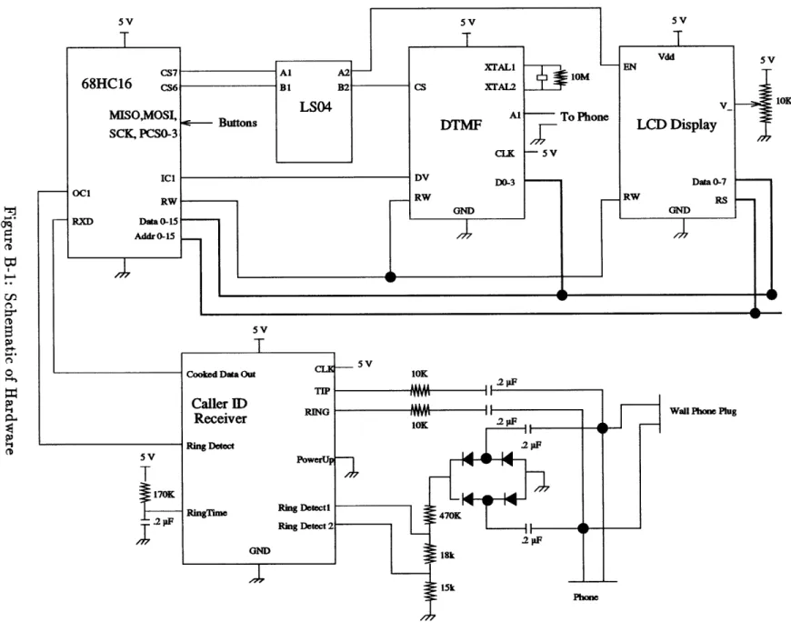
This prototype is composed of three major components, the Motorola 68HC16 eval-uation board, the Motorola Caller ID receiver, and the AT&T Telephone Answering Device (TAD) chipset. Refer to Figure 1-2 for a high level view of how these pieces fit together.
1.3.1
The Motorola 68HC16 Evaluation Board
The 68HC16 (see [4]) is a 16-bit microcontroller that runs at 16 MHz. It is an inex-pensive microcontroller and was chosen for this project mainly because the evaluation board allows development on any PC-compatible, eliminating the need for expensive microprocessor emulators and dedicated development environments. The 68HC16 contains a serial input/output module as well as several timers and chip-selects. The chip-selects are useful in that they allow the mapping of external devices onto the 68HC16 memory map without requiring external components to select the devices. The integration of all these modules makes the 68HC16 microprocessor well suited
Figure 1-2: High Level View of Hardware
for a stand-alone application such as this one.
1.3.2
The Motorola Caller ID Receiver
As mentioned in section 1.1, analog Caller ID (see [3]) is a way for the phone company
to send information about who is calling, over the same analog lines that are currently used for telephone calls. The information is frequency modulated using a technique
known as Frequency-Shift-Keying 1 (FSK) encoding, then sent between the first and second rings. So, on the customer's end, there needs to be a device that can listen
during these two rings and decode the information into serial data. That is what the Motorola Caller ID chip (the MC145447) does. There are two formats for the Caller
ID messages, single message and multiple message (see Figures 1-3 and 1-4). The
single message format includes only the phone number, date, and time. The multiple
'FSK is how most modems send data over the phone lines. They take a stream of ones and zeros, and encode a one as a certain frequency, and a zero as another frequency.
message format can include various strings as well as the number, date and time. Once the Caller ID chip recognizes actual data on the line, it demodulates it and sends it out as serial data. It also has two output pins that can be checked to see if the phone is ringing, and whether or not the chip detects a valid carrier on the line.
1.3.3
The AT&T Telephone Answering Device (TAD) Chipset
The TAD chipset is a collection of three AT&T chips that together provide the func-tionality for an all-digital answering system. It offers high compression, storing up to
20 minutes of speech in 1 Mbyte of RAM, with up to 80 minutes of total storage. It
does all the message management itself, while its microprocessor interface gives the
S2s
20 Hz Ring
30 Bytes/600 Hz MARKS DATA
0101010101
1
8 8
SBits Bits 144 Bits Max Message Type
Length
Mo - Day - Hour - Minute - Number
04 - 15 - 16 - 21 -5125551212 0.5 s 575 ms
S I
2s 1lAVYV
Checksum~J~C_
8
Bits f - - -- --- ;--- i~----2sHz Ring 20 Hz Ring
+3-0.5s 718msII
2s-MWVVAVVVVVVVV
30 Bytes/600 Hz MARKS DATA
010101011
1
Message Type
Bits Bits its itsitstsitsts Bits its Max Bits
/I I . Message Length Mother-in-Law Parameter Parameter Type Length I Parameter Type
Mo - Day - Hour - Minute - Number
04 - 15 - 16 - 21 -5125551212
Parameter Length I
_
--Chapter 2
Development Environment
The hardware for this project was developed using the 68HC16 evaluation board (see [4]). This board is a printed-circuit board that contains the 68HC16, sockets for RAM and ROM, a wire-wrap area, a parallel port, and a serial port. The serial port is connected to the serial input/output pins of the 68HC16 whereas; the parallel port is used to download programs into the "emulation ROM" on the board. This emulation ROM is actually RAM that sits in the ROM sockets, for developement purposes. A program that runs on a PC takes in Motorola S-19 hex-format code and downloads it through the parallel port into this RAM. After the code is finalized it can be burnt into ROMs, which then replace the emulation ROMs.
The software was developed on an IBM-compatible PC and was written in C. The compiler (see [6]) was supplied, free of charge, by Eric Schneider of Eris Systems in Minnesota. This compiler supports C code, assembly, and Isil, a language designed specifically for developing embedded-processor applications. This compiler can gen-erate code for various microprocessors from several different manufacturers. Since the software was written entirely in C, it would not be a difficult matter to port the code to another processor (the 68HC11, for example) in the future. This compiler can generate the S-19 hex-format code required by the 68HC16 download program.
One problem in testing the Caller ID portion of the project is that the local telephone company in Boston does not currently provide the Caller ID service. As a result it was necessary to obtain a Caller ID line simulator, which was purchased
from Rochelle Communications in Texas. This simulator is an 8-bit board that fits inside an IBM-compatible computer. It has a jack into which a phone can be plugged, and sends the caller ID information out to the phone in the same way that the phone company sends it. The Caller ID simulator can simulate both the single and multiple message types, allowing for full and convenient testing of the Caller ID receiver. Since the Caller ID simulator board software needed to be running at the same time as the 68HC16 download program, a second PC was needed to run the board (see [1]).
Chapter 3
Functional Specification
This chapter contains the high-level functional specification of the product. In other words, it describes what the user sees, what modes are available, and what the various buttons do. The first part of the specification will cover the long-term goals for the product, while the latter part will describe any differences found between the current prototype and the final product.
3.1
Full Specification
This section uses a finite state machine model to characterize all the different possible modes in which the device can be, and to describe what events cause different actions to be taken. When reading through these modes, please refer to Figure 3-1 to see a layout of the faceplate and to see what buttons are available. The different modes of operation are as follows:
1. Wait for call: This is the default mode. It displays the number of calls for the day and the number of messages.
2. Display Incoming Number: This mode displays the incoming phone number and corresponding name, if available.
3. Display Outgoing Number: This mode displays the outgoing phone number and corresponding name, if available.
Figure 3-1: Faceplate of Product
4. Browse Log: This mode allows the user to browse the log of the last 30 incoming and outgoing calls.
5. Play Announcement/Record Message: This is the answering machine mode. Control comes here after three rings and the caller's message is recorded. 6. Set Time: This mode allows the user to set the time of the internal clock. 7. Modify Announcements: This mode is for announcement maintenance. 8. Play Messages: This mode is for playing back the recorded messages.
9. Administer Name/Number Database: This mode is for name/number database management.
10. Administer Announcement/Number Database: This mode is for announce-ment/number database management.
123456789012345678901234 123456789012345678901234
Play
Browse
Clock
Annc
7:23pm June 4 4 calls
5 messages 3 new
Figure 3-2: Display for Mode 1
11. Number Entry Mode: This is a generic mode to enter a number using the phone keypad.
12. Name Entry Mode: This a generic mode to enter a string using the phone keypad.
3.1.1
Mode 1: Wait for Call
This is the default mode and the mode that comes up on power-up. In this mode, the device waits for incoming and outgoing calls. Its behavior is as follows:
* PLAY pressed: Go to mode 8. * BROWSE pressed: Go to mode 4. * CLOCK pressed: Go to mode 6. * ANNC pressed: Go to mode 7.
* Incoming Call: Go to mode 2. * Outgoing Call: Go to mode 3. * LEFT arrow pressed: Go to mode 9. * RIGHT arrow pressed: Go to mode 10.
3.1.2
Mode 2: Display Incoming Number
This mode displays the incoming number, time, and date. The name is also displayed if the number is in the name/number database. No buttons are active in
George Washington IN 617-225-7366 15:13 11/23
Figure 3-3: Display for Mode 2
George Washington OUT 617-225-7366 15:13 11/23
Figure 3-4: Display for Mode 3
this mode. As soon as the phone is hung up it returns to mode 1. As soon as the fourth ring starts it goes to mode 5.
3.1.3
Mode 3: Display Outgoing Number
This mode displays the outgoing number, time and date. The name is also dis-played if the number is in the name/number database. No buttons are active in this mode. As soon as the phone is hung up it returns to mode 1.
3.1.4
Mode 4: Browse Log
This mode allows the user to browse the call log. As soon as this mode is entered, the last call is displayed. If any incoming calls or outgoing calls are made while in browse mode, they are ignored. The behavior is as follows:
* BROWSE pressed: Go to mode 1.
George Washington OUT 617-225-7366 15:13 11/23
George Washington #5
617-225-7366 15:13 11/23
Figure 3-6: Display for Mode 5
Set Time: 15:13 11/23 CLOCK:save DELETE:abort
Figure 3-7: Display for Mode 6 * LEFT arrow pressed: Go back in log.
* RIGHT arrow pressed: Go forward in log. * All other events ignored.
3.1.5
Mode 5: Play Announcement/Record Message
This mode plays the announcement associated with the incoming call. If no an-nouncement is associated with the number in the number/anan-nouncement database, then announcement 0, the default announcement, is played. If the phone is hung up or answered before the beep, the device goes to mode 3 without recording a message. Otherwise,the device will record a message and go to mode 3 as soon as the phone is hung up or answered, whichever comes first.
3.1.6
Mode 6: Set Time
This mode allows the user to change the internal clock on the device. This time is used for tagging only the outgoing messages and is displayed in mode 1. Incoming messages use the time encoded in the Caller ID information; they don't use this clock. As soon as this mode is entered, the hour flashes. The following sequence is then used to set the time:
Slot 4 is full.
Hold down ANNC to record
Figure 3-8: Display for Mode 7 1. Left Arrow: decrease hour
2. Right Arrow: increase hour 3. CLOCK: flash minute 4. Left Arrow: decrease minute
5. Right Arrow: increase minute 6. CLOCK: flash month
7. Left Arrow: decrease month 8. Right Arrow: increase month
9. CLOCK: flash day
10. Left Arrow: decrease day 11. Right Arrow: increase day
12. CLOCK: set time and go to mode 1.
If at any time DELETE is pressed, this mode is aborted and it goes back to mode 1, leaving the time as it was before entering the mode. All other buttons and events are ignored.
3.1.7
Mode 7: Modify Announcements
This mode allows the user to record an outgoing message, or an announcement. There are 10 slots available to store into, with slot 0 being the default announcement.
303-538-2826 1 of 5
Daniel Day Lewis I 12:43
Figure 3-9: Display for Mode 8
Any number not associated with an announcement will be played announcement 0. The behavior while in this mode is as follows:
* Left Shift: decrement slot number * Right Shift: increment slot number
* DELETE: free current slot
* PLAY: listen to current slot, if full * ANNC: go to mode 1
* ANNC: if held down, record until released, and replace current message if slot is full
All other buttons and events are ignored.
3.1.8
Mode 8: Playback Messages
This mode allows the user to play back the messages. As soon as the mode is entered it begins playing, starting with the oldest message. The behavior is as follows:
* Left Shift: rewind one message with each press * Right Shift: advance one message with each press * DELETE: delete current message
* PLAY: go to mode 3
All other buttons and events are ignored. 21
505-576-7255 entry #1 Slot #4 is empty
Figure 3-10: Display for Mode 9
3.1.9
Mode 9: Administer Announcement/Number Database
This mode allows the user to modify the announcement/number database, which
contains associations between outgoing messages and a phone number. The behaviour while in this mode is as follows:
* Left Shift: go back in database
* Right Shift: go forward in database
* DELETE: delete entry
* ANNC: listen to current slot, if full
S* (on phone): switch cursor between number and announcement
*
# (on phone): if cursor on number, go to mode 10.* # (on phone): if cursor on announcement, go to mode 11.
* PLAY: go back to mode 1
All other buttons and events are ignored.
3.1.10
Mode 10: Administer Name/Number Database
This mode allows the user to modify the name/number database, which contains
associations between names and phone numbers. As soon as this mode is entered, the
phone is disconnected from the phone line to allow the keypad to be used to input names and numbers. The device's behavior while in this mode is as follows:
505-576-7255 entry #16 Cesar Chavez
Figure 3-11: Display for Mode 10
Figure 3-12: Display for Mode 11
* Right Shift: go forward one entry in database
* DELETE: delete entry
S* (on phone): switch cursor between number and name
* # (on phone): if cursor is on number, go to mode 10.
* # (on phone): if cursor is on name, go to mode 11.
* PLAY: go back to mode 1
All other buttons and events are ignored.
3.1.11
Mode 11: Number Entry Mode
This mode allows the user to enter a number using the telephone keypad. The
buttons on the keypad take on the following meaning:
* 2-9: Put number at current cursor position
* 1: Loop through 0 and 1
* 0: Accept number and return to previous mode
Figure 3-13: Display for Mode 12
* #: Accept digit and move cursor forward one position
All other buttons and events are ignored.
3.1.12
Mode 12: Name Entry Mode
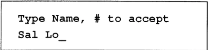
This mode allows the user to enter a name using the telephone keypad. The buttons on the keypad take on the following meaning:
* Letters: loop through possible letters for that key * 0: Accept name and return to previous mode
* *: backspace
* #: Accept letter and move cursor forward one position
All other buttons and events are ignored.
3.2
Current Implementation
This section describes the current implementation's deviation from the full specifi-cation. Because of time constraints and difficulties dealing with the local AT&T distributor, I was not able to acquire the AT&T TAD chipset. Consequently the answering machine functionality is not available in the current implementation. As a result, the functions which require the answering machine will not work. For exam-ple, in the Display Incoming Number mode, the device would normally go to the Play Announcement/Record Message mode. Rather than going there it goes immediately
back to the default mode, mode 1. Similarly, the modes Record Message, Modify An-nouncements, and Play Messages are all disabled. Everything else works as described in the previous section.
Chapter 4
Hardware Specification
This chapter will decribe the hardware in the current implementation. Since I didn't actually get my hands on the data sheets for the TAD chipset I am not able to include it here. There are 5 major parts to the hardware: the 68HC16 evaluation board, the Motorola Caller ID Receiver, the Dual-Tone Multiple-Frequency (DTMF) Touch-Tone decoder, the LCD display, and the analog interface to the phone line.
4.1
The 68HC16 Evaluation Board
The 68HC16 is a 16-bit microprocessor from Motorola that can run at 16 MHz. This processor is particularly well-suited for this application because it does not require a lot of support chips. It has a serial input/output interface built in, as well as several general purpose input/output port (GPIP) pins. It also has 10 user-configurable chip-selects so that external devices can be mapped into the 68HC16's memory map, eliminating the need for external PALs to perform this function. Eight timers are also built-in to the 68HC16. It also includes other useful features such as an eight channel analog-to-digital converter and support for multiple serial devices, both of which I am currently not using.
The 68HC16 has a 16 bit data bus and a 16 bit address bus which, along with the GPIP pins and serial I/O pins, are used to connect the 68HC16 to the other chips in the system. Sockets for RAM and ROM are already built onto the 68HC16
Evaluation Board so descriptions of the RAM and ROM connections are not included here.
4.2
The Motorola Caller ID Receiver
The Motorola Caller ID receiver has three outputs: the Caller ID serial data output, the ring detection line, and the carrier detection line. The serial data output is connected directly to the serial I/O input (RXD) on the 68HC16. As soon as valid
Caller ID information is detected, the resulting data is driven on this line. The carrier
and ring detect lines are connected to GPIP pins on the 68HC16. As long as a valid carrier is detected on the phone line the carrier detect line is pulled low. As long as
a ring is detected, the ring detect line is pulled low. The schematics for this can be
found in Appendix B.
4.3
The DTMF Touch-Tone Decoder
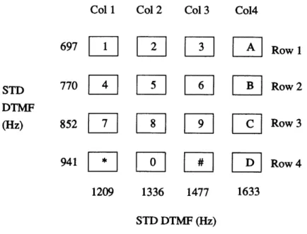
According to the Touch-Tone standard, each button on a phone keypad sends a sound that is actually a combination of two tones. The buttons are separated into columns and rows (see Figure 4-1). Each row and column is associated with a different audible
frequency. When a button is pressed two tones are produced: one for the row and one for the column. The combination of these two tones is what is sent out on the
phone line. (See [2]).
The DTMF decoder has an input pin, which is connected to the phone line, one
status output pin (DV), and 4 data output pins. The DV pin is connected to a GPIP pin on the 68HC16, and the 4 data output pins are connected to lines 8-11 of the
68HC16 data bus. The DTMF chip also has a R/W pin and an active high register enable pin. The R/W pin is connected directly to the 68HC16 R/W pin. Since the
chip selects on the 68HC16 are active low, I needed to place an inverter between
the chip select on the 68HC16 and the register enable pin on the DTMF receiver. Whenever the DTMF receiver detects a valid Touch-Tone at its input, it asserts DV
Col 1 Col 2 Col 3 Co14
697
Row
1
STD
770
L
11
Row
2
DTMF(Hz)
852
1Row
3
941
il[
Row 4
1209 1336 1477 1633 STD DTMF (Hz)Figure 4-1: DTMF Keypad Layout
and places a byte corresponding to that tone onto its 4 data output pins. In order to read the data from the chip one needs to wait for the DV pin to be asserted, then read from the address for which the chip select is configured. The schematics for this circuit can be found in Appendix B.
4.4
The LCD Display
The LCD display has two lines of 24 characters. It contains an ASCII character generator and offers several display options. The LCD display has eight input/output data pins which are connected to lines 8-15 of the 68HC16 data bus. It also contains a register enable (RE) pin, a R/W pin, and a register select (RS) pin. The R/W pin is connected to the R/W pin of the 68HC16 and the RE pin is connected to the
68HC16 chip select corresponding to the LCD display. The RS pin tells the LCD
display if the data to be transferred on the data pins is to be data or instructions. This pin is connected to the low bit of the 68HC16 address bus.
After being mapped into the 68HC16 memory map, the LCD can be accessed as two different addresses. One address is for data, and the other for instructions. The method for writing characters on the LCD is described in section 5.3. The schematics for the LCD can be found in Appendix B.
4.5
The Analog Phone-line Interface
Because the telephone line carries voltages up to 50 volts, and because the telephone ground voltage is floating relative to the 68HC16 ground, the device needs a reliable analog front-end between the phone-line and the digital circuitry. This front end is implemented using capacitors to isolate the circuitry from the line and also to remove the DC component of the telephone line. Another difficulty I run into is that I need the phone keypad for data entry. However, if I take the phone off-hook so I can send the touch tones to the DTMF receiver, I need some way to keep those tones from also going out onto the line, while still providing power to the phone so that it can generate the tones. This isolation is accomplished by a low-pass filter that can be actuated using a double-pole, double-throw relay. This relay is activated automatically whenever data needs to be entered using the keypad. At all other times the phone is connected to the line as usual.
Chapter 5
Software Specification
The software can be broken down into several major sections. These are the DTMF receiver, the input/output pins (GPIP pins), the LCD display, the Caller ID (CID) receiver, the touch tone data input interface, the main dispatch routine, the clock routines, and other miscellaneous routines.
5.1
GPIP pins
The 68HC16 has several pins that can be configured as general purpose input/output pins. These will be referred to as GPIP pins. This section contains the routines and macros that initialize the GPIP pins and provide a simple and consistent interface to access these pins. Definitions for the various pins are included in gpip.h which is included in each file that uses the pins. In order to check the state of a pin, the
macro GPIP(pin) in defined. For example, if switch 2 is pressed, GPIP(SWITCH2) will be true.
5.2
The DTMF Receiver
As described in section 4.3, the DTMF receiver listens for valid Touch-Tones on the phone line and returns a code corresponding to the tone it recognizes. Two main functions are defined to deal with setting up the DTMF decoder and receiving data
from it.
* DTMFInit: This routine takes and returns no arguments. It maps the DTMF
decoder's data output pins into address 0x40001 of the 68HC16s address space. After this mapping is done, the address 0x40001 holds the incoming touch-tone code whenever pin DV of the DTMF receiver is high. The pin DV is connected to a GPIP pin on the 68HC16 and is referred to as the DTMFBIT.
* DTMF_Get: This routine takes one argument, type, which specifies the format of the output. If type is RAW then it returns the number (from 0 to 12) that it gets from the DTMF decoder. If type is COOKED then it returns the ASCII character corresponding to the touch-tone that was pressed.
In order to determine if a valid tone is detected, it is necessary to monitor the DTMF_BIT, which is defined in gpip.h, using the expression GPIP(DTMFBIT). If a tone is detected, this expression becomes true, and the DTMF character can be read from the address 0x40001.
5.3
LCD Display
There are several functions defined to intialize LCD and send various characters to the LCD display. They are as follows:
* LCD_Init: This routine takes and returns no arguments. It maps the LCD's instruction (LCDIR) register into address 0x50000 of the 68HC16's memory map and the LCD's data (LCDDR) register into address 0x50001 of the 68HC16's memory map.
* LCDSendChar: This routine takes two arguments, data and type. The type can be either LCD_INST or LCD_DATA, depending on whether the data is an intruction to the LCD display, such as turn on cursor, or if the data is an ASCII character. If type is LCD_INST, data is written into the LCDIR register, if type is LCDDATA, data is written into the LCDDR register.
* LCDSendString: This routine takes two arguments, a string pointed to by data
and type. The type can be either LCDINST or LCD_DATA. The string pointed to by data must end in a null character (OxO).
* LCDClearScreen: This routine takes no arguments. It uses LCDSendChar to send a clear instruction to the LCD display.
* LCDMoveCursor: This routine takes two arguments, row and column. It uses
LCDSendChar to position the cursor at the specified row and column. row must be 0 or 1. column must be between 0 and 23.
5.4
CID Receiver
I wrote three routines to receive and process data from the Caller ID receiver.
* CID-get: This routine takes one arguments, a pointer to string cid_buffer.
This routine listens to the CID chip and receives the serial CID data coming from the CID chip. If no recognizable message arrives before either the next ring or when the phone is picked up, or when the ringing stops, then 0 is returned as the length of cid_buffer. If a message is received and placed into cidbuffer, then the size of cidbuffer is returned.
* CIDdate: This routine takes three arguments; length, a pointer to a string,
ciddata, and another pointer to a string, date. This routine extracts the date from a buffer containing CID data and puts it into date. If cid_data does not contain a valid date, the first byte of date will be a null (OxO).
* CID-number: This routine takes three arguments, length, a pointer to a string,
ciddata, and another pointer to a string, number. This routine extracts the phone number from a buffer containing CID data and puts it into number. If ciddata does not contain a valid number, the first byte of number will be a null (OxO).
5.5
Touch-Tone Data Input
In order to use the keypad to enter names and numbers I wrote two routines: TT_GetName
and TT_GetNumber.
* TTGetName: This routine takes two arguments; size, and a pointer to a string string. The keypad of the phone is mapped so that for the buttons 2-9, each button loops through the letters for that button; first in lowercase, then in uppercase, followed by the digit for that button. Button 1 loops between space, 0, and 1. # moves the cursor to the next position, * backspaces, and 0 accepts the string as entered. After size characters have been entered, the string is terminated with a null character (OxO) and the routine returns. If 0 was pressed before the size is reached, the entered string is terminated by a null (OxO) and the routine returns.
* TTGetNumber: This routine takes two arguments; size, and a pointer to a string string. The keypad of the phone is mapped so that for the buttons 2-9, each button enters the digit for that button. Button 1 loops between 0 and 1. # moves the cursor to the next position, * backspaces, and 0 accepts the string as entered. After size characters have been entered, the string is terminated with a null character (OxO) and the routine returns. If 0 was pressed before the size is reached, the entered string is terminated by a null (OxO) and the routine returns.
5.6
Clock Maintenance
I wrote several routines to set up and maintain a clock. They are:
* CLOCK_Init: This routine initializes a global array of four bytes beginning at clock_ticks. It also sets up a timer that calls the interrupt handler CLOCKadvance every tenth of a second.
* CLOCKadvance: This routine is an interrupt handler that advances clockticks by one.
* CLOCK_todate: This routine takes one argument, a pointer to a string date. This routine reads the current value of clockticks, converts it to the CID date format, and stores that in date.
* CLOCKfromdate: This routine takes one argument, a pointer to a string date. This routine sets the value of clockticks, taking the current time and date from date which is in the CID date format.
* CLOCKresettime: This routine calls TTGetNumber to get the current date, and uses that info to set the time using CLOCKfIromdate.
5.7
Main Dispatch Routine
This routine contains the main event loop that controls all processing in the pro-gram. This routine contains the structure for the finite-state machine described in the Functional Specification (section 3).
5.8
Utility routines
These routines include miscellaneous routines that are necessary but don't fit in any of the other major sections.
* SCIInit: This routine initializes the serial I/O module in the 68HC16 to 1200 baud, 8 data bits, no parity, 1 stop bit. It also enables the receiver.
* completenumber: This routine takes one argument, a pointer to a string number. It attempts to complete the phone number stored in number into a full 10-digit phone number. If it can't do this, it returns FAIL and puts a null (OxO) into the first character of number. If it succeeds, it returns SUCCESS and places the number into number.
Chapter 6
Conclusion
The purpose of this thesis is to build an answering machine that combines the speed and convenience of a digital answering machine with the advanced features of Caller
ID to provide the telephone user with a level of control never before found in the home.
On phone lines equipped with the Caller ID service, the phone number of the caller is encoded and sent out by the phone company. This information is sent between
the first and second ring and can be retrieved to provide the callee with the caller's phone number. The device described in this thesis contains an internal database of
phone number/name pairs which is scanned for a match as soon as the information becomes available. If the number is found in the database, the corresponding name is
displayed on an LCD display; otherwise, the number is displayed. This feature saves the user from having to remember the numbers of frequently calling parties. This database can be updated using the telephone keypad. A log is also maintained that contains all incoming and outgoing calls. As a result, the user will know who called throughout the day, even if the caller does not leave a message on the answering machine.
The other component of this device is the integration of a digital answering
ma-chine. This makes possible specialized outgoing messages, depending on who is
call-ing. For example, you can assign one greeting to your boss, another to your parents, and yet another to your friend. This combination of a digital answering machine and Caller ID makes possible new and discrete ways of screening calls. There is no longer
any need to wait for the answering machine to pick up in order to determine who is calling. When the answering machine answers, the appropriate greeting will be sent. Since the device knows who is calling, it can also know how to act on that call.
6.1
Current Implementation
The current prototype implements everything described in section 3 except for the digital answering machine. Whenever a call is made, whether outgoing or incoming, the prototype displays the number and name (if it is in the database) of the person being called or the person that is calling. It also keeps a running log of the last thirty calls made, whether incoming or outgoing. The database is modified using an input method based on using the phone's keypad to input names and numbers. The elimination of a separate keypad lessens the cost and complexity involved in building the product. Also, the fewer buttons there are, the less intimidating it will be to the consumer.
6.2
Future Directions
The current prototype is essentially a Caller ID decoder, with the next logical step being extending it to include the integrated digital answering machine. The devel-opment doesn't have to stop there. One very useful addition would be an RS-232 connection to a PC. The device could be programmed to send the Caller ID data out the RS-232 port as soon as it gets it. Then, if there is a specialized Personal Information Manager (PIM) running on the PC and it understands this Caller ID data, this feature could be integrated in with no extra hardware. A PC interface to the database would also be helpful. This would eliminate the admittedly awkward telephone keypad method for inputting data.
Another variation on this same theme would be to have a Caller ID on a PC expansion card. Then programs on the PC would have direct access to the Caller ID information and there would be no more need for the 68HC16 microprocessor or
the RAM and ROM. The digital answering machine could also be integrated into the PC expansion board. Then, the messages could be accessed on the computer as if they were audio electronic mail. A graphical interface to access all the features of the Caller ID digital answering machine would greatly increase the ease of use and flexibility of the product. It could provide a nice, consistent interface to all the features.
The increased control and flexibility provided by both Caller ID and digital an-swering machines hold great promise in terms of increasing the control that the tele-phone users have over their teletele-phones. All it takes is for someone to do it!
Appendix A
Software
/* main.c */ #include <hc6_sup.h> #include "main. h" #include "lcd.h" #include "dtmf .h" #include "database.h" #include "strings .h" #include "tt .h"#include "cid.h" o10
#include "pins .h"
isil static STRINGS, airam;
static uchar STR waitmsgl="Waiting for message"; static uchar STRoutgoing= "OUT";
static uchar STR_incomingo="IN";
static uchar STR initl={ Ox3f, Oxc, 0x2, OxO}; static uchar pref 250="61725";
static uchar pref220="61722";
static uchar area codeD="617"; 20
void MAIN(void)
uchar temp; uchar ciddata[20]; uchar count; uchar number[NUMBERSZ]; uchar date[DATE_SZ]; uchar name[NAMESZ]; uchar curdigit; 30 LCD Init(); DTMFInit(); SCI init(); PINSinit(); initdatabase(); cur_digit=0;
LCD_SendString(STR init, LCDINST); 40
LCD_ClearScreen();
/*
LCDPrNumeric(45); while(1) cur digit=0;*/
LCD_SendString(STR waitmsg, LCD DATA);
while (1) {
if (GPIP(RING_BIT) == RINGING) { 5o count=CIDget((uchar fp*)ciddata);
CIDnumber((uchar fp*)cid_data, (uchar fp*)number, count); CID date((uchar fp*)cid data, (uchar fp*)date, count);
DB_GetByNumber(NAME_NUM, (uchar fp*)name, (uchar fp*)number); LOG Add(name, number, date, INCOMING);
LCDClearScreen(); LCD MoveCursor(0,0);
LCD SendString(name, LCD_DATA);
LCD_SendString(STR incoming, LCD DATA); 60 LCD MoveCursor(1,0); LCD_PrPhoneNumber(number); LCD_MoveCursor(1,13); LCD_PrDate(date); if (SWITCH}(SWITCH1) UP)
while (SWITCH(SWITCH1) != UP)
LOG_Browse();
LCD_ClearScreen(); 70
LCD MoveCursor(0,0);
LCDSendString(STRwaitmsg, LCD_DATA);
if (SWITCH(SWITCH2) != UP) { /* Admin Name/Number Database */
while (SWITCH(SWITCH2) != UP) {}
RELAY ON; DB AdminNameNum(); LCD_ClearScreen(); LCD_MoveCursor(0,0); 80 LCD_SendString(STR_waitmsg, LCD_DATA); RELAY OFF; if (GPIP(DTMF BIT)) { temp=DTMFGet(COOKED); if (temp != 0) { number[curdigit]=temp; curdigit++; if (cur_digit==5) { so number[cur_digit]=0x0; complete_number((uchar fp*)number);
DB_GetByNumber(NAMENUM, (uchar fp*)name, (uchar fp*)numbe LOGAdd(name, number, date, OUTGOING);
LCD MoveCursor(OxO,OxO);
LCD_SendString(name, LCD DATA); LCD MoveCursor(OxO,0x15);
LCD_SendString(STR outgoing, LCD_DATA); LCD_MoveCursor(Ox1,OxO); 100
LCD_PrPhoneNumber(number); curdigit=0;
void SCI init(void) {
uchar temp2; 110 uint fp* sccr0; uint fp* sccrl; uint fp* scsr; uchar fp* scdr; sccr0=(uint fp*)SCCRO; sccrl=(uint fp*)SCCR1; scsr=(uint fp*)SCSR;
scdr=(uchar fp*)SCDR+1; / * only read lower bit of RXD buffer */
*sccr0=0xlB5; /* Set to 1200 baud */ 120 *sccrl=0x0004; /* enable the receiver */
if ((*scsr&0x40) != 0) temp2=*scdr;/* clear any waiting data "/
uchar completenumber(uchar fp *number)
{
uchar size, count;
uchar temp[NUMBERSZ];
for (size=0; size < NUMBER_SZ; size++) 130
switch(size) {
case 10:
return(SUCCESS);
case 7:
for (count=0; count < size; count++)
temp[count] =number[count];
for (count=0; count < 3; count++)
number [count] =area code [count]; 140
for (count=0; count < 7; count ++)
number [count+3] =temp [count]; number[10]=OxO; return(SUCCESS); case 5: switch (number[O]) { case '3': case '8':
for (count=O; count < size; count++)
temp [count] =number [count]; 150 for (count=0; count < 5; count++)
number[count] =pref 25 [count];
for (count=0; count < 5; count++)
number [count +5]=temp [count]; number[10]=OxO;
return(SUCCESS); case '5':
for (count=0; count < size; count++)
temp [count] =number [count];
for (count=0; count < 5; count++) 160
number [count] =pref 22 [count];
for (count=0; count < 5; count++)
number [count+ 5] =temp[count]; number[10]=Ox0;
return(SUCCESS);
default:
default:
return(FAIL);
/ * main.h */
typedef unsigned short ushort; typedef unsigned int uint; typedef unsigned char uchar;
#define FAIL 1 #define SUCCESS 0
#define TRUE 1
#define FALSE 0 10
#define NULL (void *) OxO
extern void SCI init(void);
extern main(int, char *[); extern void MAIN(void);
extern uchar complete number(uchar fp *);
#define SIMMCR OxFFA00 #define SIMTR OxFFA02
#define SYNCR OxFFA04 20
#define RSR OxFFA07 #define SIMTRE OxFFA08 #define PORTEO OxFFAll #define PORTE1 OxFFA13 #define DDRE OxFFA15 #define PEPAR OxFFA17 #define PORTFO OxFFA19 #define PORTF1 OxFFA1B #define DDRF OxFFA1D
#define PFPAR OxFFA1F 30
#define SYPCR OxFFA21 #define PICR OxFFA22 #define PITR OxFFA24 #define SWSR OxFFA27 #define TSTMSRA OxFFA30
#define #define #define #define #define #define #define #define #define #define #define #define #define #define #define #define #define #define #define #define #define #define #define #define #define #define #define #define #define #define #define #define #define #define #define #define TSTMSRB TSTSC TSTRC CREG DREG CSPDR CSPARO CSPAR1 CSBARBT CSORBT CSBARO CSORO CSBAR1 CSOR1 CSBAR2 CSOR2 CSBAR3 CSOR3 CSBAR4 CSOR4 CSBAR5 CSOR5 CSBAR6 CSOR6 CSBAR7 CSOR7 CSBAR8 CSOR8 CSBAR9 CSOR9 CSBAR10 CSOR10 RAMMCR RAMTST RAMBAH RAMBAL OxFFA32 OxFFA34 OxFFA36 OxFFA38 OxFFA3A OxFFA41 OxFFA44 OxFFA46 OxFFA48 OxFFA4A OxFFA4C OxFFA4E OxFFA50 OxFFA52 OxFFA54 OxFFA56 OxFFA58 OxFFA5A OxFFA5C OxFFA5E OxFFA60 OxFFA62 OxFFA64 OxFFA66 OxFFA68 OxFFA6A OxFFA6C OxFFA6E OxFFA70 OxFFA72 OxFFA74 OxFFA76 OxFFB00 OxFFBO2 OxFFBO4 OxFFBO6
#define #define #define #define #define #define #define #define #define #define #define #define #define #define #define #define #define #define #define #define #define #define #define #define #define #define #define #define #define #define #define #define #define #define #define #define QMCR QTEST QILR QIVR SCCRO SCCR1 SCSR SCDR QPDR QPAR QDDR SPCRO SPCR1 SPCR2 SPCR3 SPSR RRO RR1 RR2 RR3 RR4 RR5 RR6 RR7 RR8 RR9 RRA RRB RRC RRD RRE RRF TRO TR TR2 TR3 OxFFC00 OxFFC02 OxFFC04 OxFFC05 OxFFC08 OxFFCOA OxFFCOC OxFFCOE OxFFC15 OxFFC16 OxFFC17 OxFFC18 OxFFC1A OxFFC1C OxFFC1E OxFFC1F OxFFD00 OxFFDO2 OxFFDO4 OxFFDO6 OxFFD08 OxFFDOA OxFFDOC OxFFDOE OxFFD00 OxFFDO2 OxFFDO4 OxFFD06 OxFFD08 OxFFDOA OxFFDOC OxFFDOE OxFFD20 OxFFD22 OxFFD24 OxFFD26
#define #define #define #define #define #define #define #define #define #define #define #define #define #define #define #define #define #define #define #define #define #define #define #define #define #define #define #define #define #define #define #define #define #define #define #define TR4 TR5 TR6 TR7 TR8 TR9 TRA TRB TRC TRD TRE TRF CRO CR1 CR2 CR3 CR4 CR5 CR6 CR7 CR8 CR9 CRA CRB CRC CRD CRE CRF GPTMCR GPTMTR ICR PDDR GPTPDR OC1M OC1D TCNT OxFFD28 OxFFD2A OxFFD2C OxFFD2E OxFFD30 OxFFD32 OxFFD34 OxFFD36 OxFFD38 OxFFD3A OxFFD3C OxFFD3E OxFFD40 OxFFD41 OxFFD42 OxFFD43 OxFFD44 OxFFD45 OxFFD46 OxFFD47 OxFFD48 OxFFD49 OxFFD4A OxFFD4B OxFFD4C OxFFD4D OxFFD4E OxFFD4F OxFF900 OxFF902 OxFF904 OxFF906 OxFF907 OxFF908 OxFF909 OxFF90A
#define PACTL OxFF90C #define PACNT OxFF90D #define TIC1 OxFF90E #define TIC2 OxFF910 #define TIC3 OxFF912 #define TOC1 OxFF914
#define TOC2 OxFF916 150
#define TOC3 OxFF918 #define TOC4 OxFF91A #define TI405 OxFF91C #define TCTL1 OxFF91E #define TCTL2 OxFF91F #define TMSK2 OxFF921 #define TFLG1 OxFF922 #define TFLG2 OxFF923 #define CFORC OxFF924
#define PWMC OxFF924 160
#define PWMA OxFF926 #define PWMB OxFF927 #define PWMCNT OxFF928 #define PWMBUFA OxFF92A #define PWMBUFB OxFF92B #define PRESCL OxFF92C #define ADCMCR OxFF700 #define ADTEST OxFF702 #define ADCPDR OxFF706
#define ADCTLO OxFF70A 170
#define ADCTL1 OxFF70C #define ADSTAT OxFF70E #define RJURRO OxFF710 #define RJURR1 OxFF712 #define RJURR2 OxFF714 #define RJURR3 OxFF716 #define RJURR4 OxFF718 #define RJURR5 OxFF71A #define RJURR6 OxFF71C
#define #define #define #define #define #define #define #define #define #define #define #define #define #define #define #define #define RJURR7 LJSRRO LJSRR1 LJSRR2 LJSRR3 LJSRR4 LJSRR5 LJSRR6 LJSRR7 LJURRO LJURR1 LJURR2 LJURR3 LJURR4 LJURR5 LJURR6 LJURR7 OxFF71E OxFF720 OxFF722 OxFF724 OxFF726 OxFF728 OxFF72A OxFF72C OxFF72E OxFF730 OxFF732 OxFF734 OxFF736 OxFF738 OxFF73A OxFF73C OxFF73E
/ * cid.c */;
<hc6_sup.h> "main.h" "cid.h" "pins .h"
uchar CID_get(uchar fp *cid_buffer)
{
uint templ; uchar temp2; uchar count; uchar Uflag; uchar length; uchar overflow;/ * Stores incoming characters */ /* Stores status flag */
/* cid buffer counter */
/* says if char is an initial U */
uint fp* scsr; uchar fp* scdr;
scsr=(uint fp*)SCSR;
scdr=(uchar fp*)SCDR+1; /* only read lower bit of RXD buffer */
if ((*scsr&Ox40) != 0) temp2=*scdr;/* clear any waiting data */
count=0; Uflag=l; overflow=0;
/ * reset cid buffer counter */
/* Set Uflag */
while (1) { /* Look for message type */
while(((templ=*scsr)&0x40) == OxO) {} if ((templ&Ox8) != 0) overflow=l; temp2=*scdr; if ((templ & 0x2) == 0) if (temp2==0x4) break;
Spin until receive buffer is full */ store incoming char */
only keep char if no errors */ If messagetype O4 */ then move on */ #include #include #include #include
while (1) { /* This is the message length */ while(((templ=*scsr)&Ox40) == OxO) {}
if ((templ&0x8) != 0) overflow=1; 40
temp2=*scdr; /
if ((templ & Ox2) == 0) { /
length=temp2; / break; /
}
while (1){ / if (count==length) break; / while(((temp l=*scsr)&0x40) == if ((templ&Ox8) != 0) overflow=1; temp2=*scdr;if ((templ & Ox2) == 0) { cid buffer[count]=temp2;/ count++;
cid_buffer [count] =OxO;
return(count);
* Spin until receive buffer is full */ * store incoming char */
* only keep char if no errors */ * This is the length */
* then move on */
* this is the data */
* break if received length chars */ OxO) {}
/ * Spin until receive buffer is full */ /* store incoming char */
/* only keep char if no errors */
* put char in cid buffer */
/
* increment cid buffer counter *//* return length of cid buffer */
void CIDdate(uchar fp* cid_data, uchar fp* date, uchar length)
{
uchar count; if (length==O) {
date[O]=OxO;
} else {
for (count=O; count < 8; count ++)
date[count]=ciddata[count]; date[count]=OxO;
void CID number(uchar fp* cid_data, uchar fp* number, uchar length)
{
uchar count; length-=8; switch (length) { case 10: 80for (count=O; count < 10; count ++)
number [count] =cid_data[count+8]; number [count]= OxO;
break;
case 7:
number[O]= '6'; number[1]=' 1'; number[2]= '7 ';
for (count=O; count < 7; count ++)
number [count+3]= cid_data[count+8]; 90
number [count+3]=OxO; break; default: number[O]= OxO; break;
}
/ * cid.h */
#define CID ERROR 0 #define CID_NORM 1
#define CID_EXT 2
extern uchar CIDget(uchar fp *);
extern void CID date(uchar fp*, uchar fp*, uchar); extern void CID_number(uchar fp*, uchar fp*, uchar);
/ * database.c */ #include <hc6_sup.h> #include "main.h" #include "lcd.h" #include "database.h" #include "dtmf .h" #include "strings .h" #include "tt .h"
#include "pins .h" o10
isil static STRINGS, a_iram;
static uchar browse ="Browser";
static uchar logemptyD="The log is empty."; static uchar in[="IN";
static uchar out[]="OUT";
static uchar STRemptyfl="empty"; static uchar STR_entry[]="entry #";
static uchar enternumber[]="Enter Valid Phone Number";
static uchar entername="Enter Name"; 20
isilstatic DBASE, a full;
NAMENUM FLD name numdb[NAME_NUMBER SZ]; NUM MSG_FLD num msgdb[NUMMSGSZ];
LOG-ENTRY phonelogdb[PHONELOGSZ]; uchar phonelog_cur; uchar phonelog_full; uchar DB Init(uchar db) { 30 uchar i; switch (db) {
case NAME NUM:
namenum_db[i].valid=FALSE; return(SUCCESS);
case NUM MSG:
for (i=O; i < NUMMSG_SZ; i++)
nummsg_db[i] .valid=FALSE;
return(SUCCESS); default:
return(FAIL);
uchar DBDelete(uchar db, uchar entry)
{
switch (db) {
case NAME NUM:
if ((entry >= 0) && (entry < NAME_NUMBERSZ)) { namenum_db [entry] .valid=FALSE;
return(SUCCESS);
return(FAIL);
case NUM MSG:
if ((entry >= 0) && (entry < NUM_MSG_SZ)) { num msgdb[entry] .valid=FALSE;
return(SUCCESS);
}
return(FAIL); default:
return(FAIL);
uchar DB_GetByEntry(uchar db, uchar entry, uchar fp *datal, uchar fp *data2)
{
switch (db) {
if (name num_db[entry].valid== FALSE) return(FAIL); if ((entry >= 0) && (entry < NAMENUMBER_SZ)) {
strcpy(datal, name num db[entry] .name);
strcpy(data2, name num db[entry].number);
return(SUCCESS); } else {
return(FAIL);
case NUMMSG: 80
if (num_msg db[entry].valid==FALSE) return(FAIL); if ((entry >= 0) && (entry < NUM_MSG SZ)) {
strcpy(datal, nummsgdb[entry].number); data2 [0]=nummsg db[entry] .message;
return(SUCCESS);
} else {
return(FAIL);
so90
uchar DB_GetByNumber(uchar db, uchar fp *datal, uchar fp *data2)
{
uchar count;
switch (db) {
case NAME NUM:
for (count=0; count < NAME_NUMBER SZ; count++) {
if (name_num_db[count].valid==TRUE) { if (strcmp(data2, name_numdb[count].number)==i-- { strcpy(datal, name_num_db[count].name); return(SUCCESS);
}
}
datal[0]=0xO; return(FAIL);case NUM MSG:
for (count=O; count < NUMMSG_SZ; count++) {
if (nummsg_db[count] .valid==TRUE) { 110
if (strcmp(datal, nummsgdb[count]. number)==0) { data2[0]=num msg db[count] .message; return(SUCCESS);
data2[0]=0x0; return(FAIL);
120
uchar DB_Add(uchar db, uchar entry, uchar fp *datal, uchar fp *data2) switch (db) {
case NAME NUM:
if ((entry >= 0) && (entry < NAME_NUMBER_SZ)) { strcpy(namenum db[entry].name, datal); strcpy(namenum db[entry].number, data2); namenum_db [entry]. valid=TRUE;
return(SUCCESS); 1o
}else {
return(FAIL);
}
case NUM MSG:
if ((entry >= 0) && (entry < NUM_MSG_SZ)) { strcpy(num msg_db[entry].number, datal); num_msg_db[entry].message=data2 [0]; num_msg_db[entry] .valid=TRUE; return(SUCCESS); } else { 140 return(FAIL);
}
void LOG Init(void)
{
int i;
for (i=O; i < PHONELOG_SZ; i++) phonelog db[i].valid=FALSE;
phonelogcur=0; 150 phonelog_full=FALSE; void initdatabase(void) DBInit(NAME_NUM); DB_Init(NUMMSG); LOG Init(); 160
void LOGAdd(uchar fp*name, uchar fp*number, uchar fp*date, uchar type) strcpy(phonelog_db[phonelog_cur] .name, name);
strcpy(phonelog db[phonelog_cur] .number, number);
/*
strcpy(phonelog db[phonelog_ cur]. date, cur dateO );
*/
if (type==INCOMING)
strcpy(phonelog_db[phonelog_cur] .date, date);
else 170
phonelog db[phonelog cur] .date [0]= OxO;
phonelog db[phonelog_cur].type= type; phonelogdb[phonelog-cur] .valid=TRUE; phonelogcur++;
if (phonelog cur==PHONELOG SZ) { phonelogcur=0;