HAL Id: hal-01265963
https://hal.archives-ouvertes.fr/hal-01265963
Submitted on 2 Feb 2016
HAL is a multi-disciplinary open access
archive for the deposit and dissemination of sci-entific research documents, whether they are pub-lished or not. The documents may come from teaching and research institutions in France or abroad, or from public or private research centers.
L’archive ouverte pluridisciplinaire HAL, est destinée au dépôt et à la diffusion de documents scientifiques de niveau recherche, publiés ou non, émanant des établissements d’enseignement et de recherche français ou étrangers, des laboratoires publics ou privés.
A Fiber Fabry-Perot Interferometer for Geophysics
Applications
Han Cheng Seat, Michel Cattoen, Françoise Lizion, M. Suleiman, F Boudin, J
Chéry, C Brunet, Patrick Bernard, P Chawah, A Sourice, et al.
To cite this version:
Han Cheng Seat, Michel Cattoen, Françoise Lizion, M. Suleiman, F Boudin, et al.. A Fiber Fabry-Perot Interferometer for Geophysics Applications. IEEE SENSORS 2015, Nov 2015, Busan, South Korea. �10.1109/ICSENS.2015.7370316�. �hal-01265963�
A Fiber Fabry-Perot Interferometer for Geophysics
Applications
H.C. Seat11,2, M. Cattoen1,2, F. Lizion1,2, M. Suleiman3, F. Boudin4, J. Chéry4, C. Brunet5, P. Bernard5, P. Chawah4,6, A. Sourice6, G. Plantier6, D. Boyer7, A. Cavaillou7, S. Gaffet7
1
CNRS, LAAS, F-31400 Toulouse, France; 2Univ de Toulouse, INP, LAAS, F-31400 Toulouse, France
3
Laboratoire National des Champs Magnétiques Intenses, CNRS-INSA-UJF-UPS, F-31400 Toulouse, France
4
Géosciences Montpellier, Univ de Montpellier 2, F-34095 Montpellier, France
5
Institut de Physique du Globe de Paris, F-75005 Paris, France
6
Ecole Supérieure d'Electronique de l'Ouest, F-49107 Angers, France
7
Laboratoire Souterrain à Bas Bruit, F-84400 Rustrel, France Email: [email protected]
Abstract—A fiber interferometer interfaced to 3
geo-mechanical elements is presented for applications in geophysics. The fiber sensor is based on an extrinsic fiber Fabry-Perot interferometer (EFFPI) which incorporates a modulation scheme to lock the interferometer at quadrature and to enable displacement measurements below a quarter of the interrogating wavelength. It operates over a relatively large frequency dynamic of ~500000 with a precision better than 2 nm. The fiber interferometer is next interfaced to a differential hydrostatic long baseline inclinometer, a 3-axis borehole tiltmeter and a single-axis seismometer, respectively. Results obtained demonstrate that the fiber interferometrically-interrogated instruments exhibit performances equivalent to or even surpassing those of the reference instruments employed for comparison during their deployment to an underground test site since March 2012.
Keywords—modulation-based extrinsic fiber Fabry-Perot interferometer; fiber optique hydrostatic inclinometer; fiber optique borehole tiltmeter; fiber optique seismometer
I. INTRODUCTION
Earthquakes, volcanic eruptions as well as human activities (such as underground mine tunneling and storage facilities) can induce large strain states and hence movements in the earth's surface [1]. The subsequent vibrations generated by these events can nevertheless be remotely detected away from their epicenters [2]. In the context of natural risks, the catastrophic consequences of such vibrations thus can not be more strongly emphasized by the recent events in Nepal (April 2015, M7.8), in Japan (March 2011, M9.0) and off the coast of Sumatra (Indonesia, December 2004, M9.1-M9.3), etc. These are exemplified by the damages caused to entire cities/villages and, more sadly, the huge loss of lives as a direct consequence of the quakes or indirectly from the aftershocks, tsunamis and/or landslides. In risk prevention or management, it is thus of great interest to be able to detect these minute vibrations with sufficiently sensitive equipment. Although complete prediction of earthquake occurrences are beyond the reach of current research [3], the precious seconds or even minutes gained in predicting these events and hence in alerting or warning the population centers can be crucial to saving lives during
evacuation, particularly during the principal quakes and the oft-more dangerous aftershock tremors.
Although space-based systems such as GPS and InSARs (interferometric synthetic aperture radars) are widely used for their large geographical coverage, they do not have sufficient spatial and temporal resolutions for detecting such weak vibrations [4]. More localized in-situ instruments (hydrostatic inclinometers, borehole tiltmeters and seismometers) can also be used over different operating bandwidths but have to be deployed in certain quantities to provide good geographical coverage [5],[6],[7]. Optical techniques, such as fiber interferometers, are particularly suitable for this task in geophysics because of their numerous advantages which are unmatched by traditional instruments. The intrinsic properties of the optical glass fiber, such as its dielectric nature and, hence, immunity to electromagnetic interferences, lightning strikes and zero explosion risks, its flexible fiber geometry, low attenuation, very wide bandwidth, and multiplexing capability favor sensor systems based on the optical fiber for deployment in the field for remote sensing. Further, coupled to interferometric detection techniques, these fiber sensors can offer extreme sensitivity and precision in performance and can be made suitable for applications beyond typical optical metrology.
Fiber optic interferometers are today a relatively mature technology and have been commercially exploited. The potential extreme performance achievable with these devices has seen their uses in various high-precision metrological applications where very high accuracy and resolution are desired [8]. In addition, these sensors are highly suitable for constructing multiple probes grouped into networks for multi-point sensing or to provide measurement cover over a large geographical zone. This can technically improve the spatial resolution as well as the measurement accuracy of the particular parameter under detection or study. One of the domains in which fiber interferometers can offer superior performances together with field advantages over traditional electrical and/or electronic sensors is in geophysics for ground-based in-situ measurement campaigns over the long term.
We report in this work a fiber sensor based on the extrinsic fiber Fabry-Perot interferometer (EFFPI) coupled to three geomechanical instruments for long-term monitoring of the earth's free surface movements [9]. The EFFPI incorporates a modulation scheme allowing the object's directional sense to be determined as well as displacements below the interrogating wavelength to be precisely measured. Both the EFFPI and geomechanical elements have been assembled to form a quasi-monolithic structure to ensure accurate transmission of the disturbance by the geomechanical transducers to the fiber sensor. This research work has been carried out under the auspices of the French National Research Agency Natural Risk ANR LINES project.
II. OPERATING PRINCIPLES
A. Modulation-based EFFPI
The modulation-based extrinsic fiber Fabry-Perot interferometer is schematically illustrated in Fig. 1. The interrogating wavelength (λ) from a temperature-regulated fiber pigtailed 1310 nm DFB-type laser diode (DFB-LD) is coupled by a fiber circulator (FC) to an external target through a collimator (C). Here, the use of a mirror target introduces a double reflection (DR) from the sensing beam.
Fig. 1. Schematic of modulation-based EFFPI for displacement measurement (TEC: thermo-electric cooler; LDC: laser diode current controller; ISO: optical isolator; SF: sensing fiber; PD: photodetector; DAQ unit: data acquisition unit; Synchron.: synchronization)
This wave doubly reflected off the target (T) then combines with the reference wave reflected at SF end to form the interference signal. Current modulation from a modulation unit is applied to first π/2 phase-shift the signal to achieve a signal pair given by Vx = V0x + Vmxcos(Δθ) and Vy = V0y + Vmycos(Δθ +
π/2 + ε) = V0y + Vmysin(Δθ + ε), where Vx and Vy are the
quadrature signals, V0x and V0y their dc components, Vmx and Vmy their or ac amplitudes, respectively. ε accounts for any
out-of-quadrature phase error. The desired displacement d is then retrieved from Δθ = 8πnd/λ via phase demodulation with n the cavity refractive index (~1 for air). A second modulation is simultaneously applied to generate a reference displacement and enables quasi-static movements or very slowly-evolving displacements with amplitudes below λ/4 to be detected.
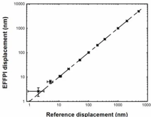
The calibration of the EFFPI sensor against a reference piezo-electric transducer (PZT) from Polytech PI with a quoted precision of 2 nm is plotted in Fig. 2 over a 2 nm – 5 µm range beyond which the PZT response is no longer linear. The result
indicates very good linearity between the two devices with the precision of the EFFPI sensor evaluated to be better than 2 nm over 10-3 – 500 Hz (or frequency dynamic = 500000).
Fig. 2. Calibration of EFFPI sensor against reference PZT
B. Fiber Interferometric Hydrostatic Long Baseline Inclinometer
The operating principle behind the EFFPI-interrogated hydrostatic long baseline inclinometer (ILB-LINES) is a pair of liquid-filled communicating vases whose baseline is defined by the length of a hydrostatic tube joining the two vases. Any ground tilt or inclination will induce a liquid level variation in both vases albeit in opposite directions. A differential configuration is adopted here with two EFFPI probes employed to detect liquid level variations. The displacement associated with this variation is limited to ±1 mm as shown in Fig. 3(a) with a relative error due to the cosine α term estimated at less than 0.005 %. A linear variable differential transducer (LVDT) is integrated as the reference sensor, as illustrated by Fig. 3(b) for ILB-LINES having a combined baseline of 150 m.
Fig. 3. (a) Differential set-up employed in LINES; (b) Prototype ILB-LINES for deployment
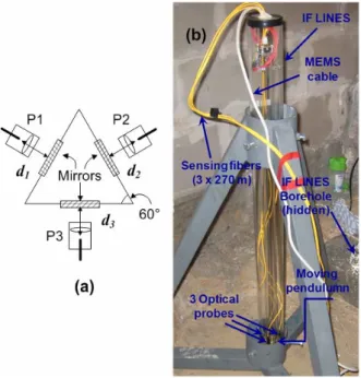
C. Fiber Interferometric Borehole Tiltmeter
A second EFFPI sensor is interfaced to a simple pendulum system made from an all-glass superstructure to form IF-LINES. The detection basis is a tri-axial set-up where 3 EFFPI probes are positioned at 120° apart as illustrated in Fig. 4(a), thus allowing angular movements from the mobile pendulum mass to be detected. This tri-axial redundancy also has the major advantage of compensating common-mode perturbations
(atmospheric pressure variation, temperature effects and other common-mode noises, etc) since d1 + d2 + d3 = 0 theoretically.
The complete instrument is shown in Fig. 4(b) before its insertion into a borehole at the test site. IF-LINES is ~1 m long and has a resolution of ~1 nanorad. To shield IF-LINES from any damages, it is sealed into an all-silica protection tube.
Fig. 4. (a) Tri-axial detection in IF-LINES; Image of prototype IF-LINES before installation in borehole
D. Fiber Interferometric Seismometer
The third instrument developed here is a fiber seismometer, SISMO-LINES, in which a 1 km long EFFPI probe is coupled to a 2-Hz geophone to form a quasi-monolithic structure. Movements from the geophone's mobile mass are thus directly detected, as schematically shown in Fig. 5(a).
Fig. 5. (a) Mobile mass movement detected by EFFPI sensor; (b) Image of prototpe SISMO-LINES
The complete SISMO-LINES, as shown in Fig. 5(b), has a maximum displacement of 4 mm (or ±2 mm from its equilibrium position) due to the mobile mass travel range and can be configured for displacement or velocity measurements.
III. RESULTS AND DISCUSSION
The prototype instruments developed in this work, namely ILB-LINES, IF-LINES and SISMO-LINES, have been deployed to a low-noise underground test site (LSBB) in Rustrel, South of France (Fig. 6) at end Feb 2012. The instruments and their control modules are installed 300 m apart in a gallery which is located ~800 m from the principal tunnel's entrance. ILB-LINES and SISMO-LINES are oriented along the gallery's axis (N-S direction) while Probe 1 from IF-LINES is N-oriented. Onsite characterization of the instruments using periodic earth tides with 12-hr periods is performed to validate their operation under real solicitation since these tides are considered the "natural" calibration basis in geophysics.
Fig. 6. Installation of LINES-related instruments in LSBB test gallery
The experimental results obtained for ILB-LINES are illustrated in Fig. 7 during the April 2012 Sumatra earthquake.
Fig. 7. ILB-LINES response to M8.7 Sumatra Earthquake in April 2012. Tremors superpositioned onto highly-resolved earth tides detected by both EFFPI and LVDT sensors. ILB-LINES has a combined baseline of 150 m, a resolution of better than 2x10-11 rad (see inset) and operates from <10-3–10 Hz
It is observed that tremors from the quake, with a total duration lasting ~5.5 hrs, are superpositioned onto the periodic
earth tides, and are detected with a very good resolution by the interferometric and LVDT devices. Although a complete analysis of the quake event to evaluate pre-cursors is beyond the scope of this paper, a time lapse of ~1 hr – 1 hr 15 mins is observed between perceptible tremors up to the main quake. The inset illustrates the difference between the EFFPI and LVDT measurements of ~2x10-11 radians, enabling the performance of ILB-LINES to be validated.
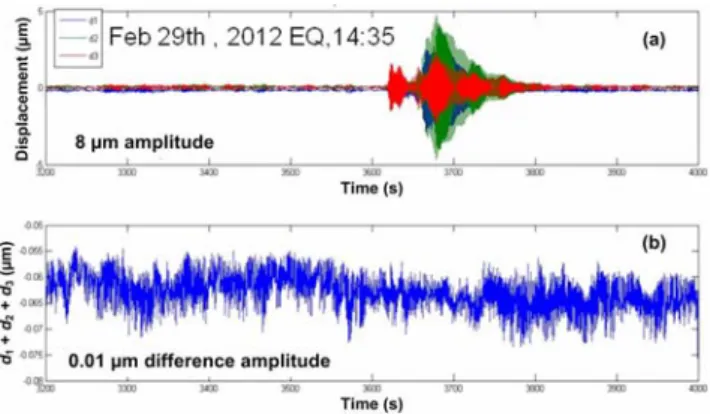
IF-LINES, configured for operating over from DC to ~10 Hz, is installed in a 1.5 m deep borehole which is ~500 m underground. Its response to a quake event confirms its capacity to compensate common-mode noises via its tri-axial redundancy measurements where d1 + d2 + d3 ~ 10 nm,
implying a small offset which is attributed to the slightly non-symmetric conception of the instrument, as shown in Fig. 8.
Fig. 8. (a) IF-LINES response (DC – 10 Hz) to M6.5 Japan Earthquake at end Feb 2012 with max. amplitude of ~8 µm detected; (b) Tri-axial redundancy validates instrument's capacity for common-mode compensation
SISMO-LINES (>2 Hz) is installed on a flat reinforced concrete slab adjacent to a reference Streckeisen STS2 seismometer. The response from both instruments is plotted on a seismograph in acceleration values in Fig. 9.
Fig. 9. Response of SISMO-LINES and reference STS2 seismometer to M8.7 Sumatra Earthquake in April 2012. Comparable background noise and quake amplitudes detected by both instruments
The background noise level from SISMO-LINES is found to be comparable to that from the STS2 device. In addition, the
acceleration amplitudes detected by SISMO-LINES during the actual quakes are identical to those measured with the STS2 seismometer which is a large bandwidth sensor (10 kHz). In the context of risk management, it is observed that the peak shock occurred at ~09:32 hrs with secondary tremors dispersed over 5 – 10 min periods.
IV. CONCLUSIONS
Three instruments, namely a fiber interferometric hydrostatic long baseline inclinometer (ILB-LINES), a fiber interferometric borehole tiltmeter (IF-LINES) and a fiber interferometric seismometer (SISMO-LINES), have been developed for geophysics instrumentation under the Natural Risks program of the French National Research Agency. These have subsequently been tested in the laboratory and deployed out into a test tunnel for preliminary field trials. Comparison of in-situ measurements with respective reference instruments demonstrated that the LINES instruments offer characteristics which are comparable (ILB-LINES and SISMO-LINES) or even surpass (IF-LINES) those of their reference counterparts. Further recording and analysis of the ground data are required to optimize and investigate extremely slow geophysics events. Future work will involve rendering these instruments more robust for field trials in various remote locations.
ACKNOWLEDGMENT
The authors acknowledge support from the French National Research Agency for this research via the grant ANR-08-RISKNAT-012-02/LINES.
REFERENCES
[1] S. W. Smith and W. V. de Lindt, "Strain adjustments associated with earthquakes in Southern California," Bull. Seismol. Soc. Am., vol.59, nr. 4, 1969.
[2] A. A. Tronin, "Remote sensing and earthquakes: A review," Phys. Chem. Earth, vol. 31, pp. 138-142, 2006.
[3] J. G. Robert, D. D. Jackson, Y. Y. Kagan and F. Mulargia, "Earth-quakes cannot be predicted," Science, vol. 275, pp. 1616-1617, 1997. [4] M. Wei, D. Sandwell, B. Smith-Konter, "Optimal combination of InSAR
and GPS for measuring interseismic crustal deformation", Adv. Space Res., vol. 46, pp. 236-249, 2010
[5] D. C. Agnew, "Strainmeters and tiltmeters," Rev. Geophys., vol. 24, nr. 3, pp. 579-624, 1986.
[6] F. Boudin, S. Allgeyer, P. Bernard, H. Hébert, M. Olcay, R. Madariaga, M. El-Madani, J.-P. Vilotte, S. Peyrat, A. Nercessian, B. Schurr, M.-F. Esnoult, G. Asch, I. Nunez and M. Kammenthaler, "Analysis and modelling of tsunami-induced tilt for the 2007, M = 7.6, Tocopilla and the 2010, M = 8.8 Maule earthquakes, Chile, from long-base tiltmeter and broadband seismometer records," Geophys. J. Int., vol. 194, nr. 1, pp. 269-288, 2013.
[7] P. Chawah, J. Chéry, F. Boudin, M. Cattoen, H. C. Seat, G. Plantier, F. Lizion, A. Sourice, P. Bernard, C. Brunet, D. Boyer and S. Gaffet, "Borehole simple pendulum tiltmeter based on a triaxial optical-fiber displacement sensor," Geophys. J. Int., in press.
[8] B. H. Lee, Y. H. Kim, K. S. Park, J. B. Eom, M. J. Kim, B. S. Rho and H. Y. Choi, "Interferometric fiber optic sensors," Sensors, vol. 12, pp. 2467-2486, 2012.
[9] H. C. Seat, P. Chawah, M. Cattoen, A. Sourice, G. Plantier, F. Boudin, J. Chéry, C. Brunet, P. Bernard and M. Suleiman, "Dual-modulation fiber Fabry-Perot interferometer with double reflection for slowly-varying displacements", Opt. Lett., vol. 37, nr. 14, p. 2886-2888, 2012.