The Effect of Compositional and Geometrical Changes
to the Bending Strength of the Ghanaian Ceramic Pot Filter
by Travis Watters
SUBMITTED TO THE DEPARTMENT OF CIVIL AND ENVIRONMENTAL ENGINEERING IN PARTIAL FULFILLMENT OF THE REQUIREMENTS FOR THE
DEGREE OF
ENGINEERING IN CIVIL AND ENVIRONMENTAL ENGINEERING AT THE
MASSACHUSETTS INSTITUTE OF TECHNOLOGY JUNE 2010
© Travis Watters. All rights reserved.
The author hereby grants to MIT permission to reproduce and to distribute publicly paper and electronic copies of this thesis document in whole or in part
in any medium now known or hereafter created.
MASSACHUSETTS INSTITUTE OF TECHNOLOGY
JUL
15
2010
LIBRARIES
ARCHIVES
Signature of Author:Department of Civil and Environmental Engineering May 21, 2010 Certified by:
Accepted by:
Susan Murcott Senior Lecturer of Civil and Environmental Engineering Jhisupervisor
Danieit ewneifo
Chairman, Departmental Committee for Graduate Students MASTERS OF
The Effect of Compositional and Geometrical Changes
to the Bending Strength of the Ghanaian Ceramic Pot Filter
by Travis Watters
Submitted to the Department of Civil and Environmental Engineering on May 21, 2010, in Partial Fulfillment of the Requirements for the Degree of Masters of Engineering in Civil and
Environmental Engineering ABSTRACT
Pure Home Water (PHW) is a non-profit organization with the goal of providing safe drinking water through household water treatment and storage (HWTS) to the inhabitants of Ghana, particularly in the Northern Region. To this end, PHW has pursued the distribution and training in the use of the Kosim ceramic pot filter (CPF), and now wishes to pursue its manufacture. Laboratory studies have found the CPF to be between 97.8 and 100% efficient in the removal of E. coil bacteria.
One of the main reasons for a household's discontinued use of the CPF is breakage. In a follow-up monitoring of 1,000 homes receiving CPFs after an emergency flood distribution in 2008, the rate of breakage was found to be 12%. To address this critical problem, the author performed a three-point bending test on rectangular-prism clay samples with varying recipes and thicknesses in an attempt to determine bending strengths associated with the recipes with the aim of
moderating the lip failure due to the possible failure mechanism of bending stress.
Filter recipes were assigned numbers 1 through 14 based on combustible type, presence or absence of grog, combustible volume, and manufacturing process. The recipes which
incorporated only fine, sieved combustible materials yielded the highest mean bending strengths. Statistically significant decreases in bending strength were realized with the increase of
combustible mass. The inclusion of grog was generally found to have no statistically significant impact on the bending strength. Experimentally observed gains in bending strength with
increased thickness supported theoretical strength gains with the square of the thickness. The variable of firing condition was found to be a significant but unquantifiable variable in the bending strength of the samples. In all cases, the lower bound of a 95% confidence interval of the mean bending strength of the materials was found to exceed the expected bending stress on the filter lip due to predicted loading conditions.
It is recommended that PHW pursue the manufacture of a fine-and-waste rice husk recipe with a 3:8 combustible-to-clay ratio without the inclusion of grog. It is recommended that the lip of the filter be thickened to 25 mm. It is recommended that pyrometric cones be placed in the spyhole and door of the kiln during each firing and monitored once an hour until the guide cone bends, and once every fifteen minutes thereafter until the firing cone bends, at which time firing should cease. It is recommended that consultation with kiln designer Manny Hernandez be maintained so as to create even firing conditions within the kiln.
Thesis Supervisor: Susan Murcott
ACKNOWLEDGEMENTS
I wish to thank the following people for their assistance in completing this thesis.
Susan Murcott, fellow traveler and advisor. To say that without her, this thesis would be impossible, is to state an obvious truth. It is because of her work in founding Pure Home Water and her career in the developing world in general that I have had the unspeakable good fortune to travel the world and leverage my efforts in support of the needy and unseen.
Manny Hemandez, fellow traveler, kiln/press designer/builder, and overall benchmark-setter for toughness, discipline, and dedication. I have never seen a person work so hard or so consistently or with such enthusiasm. If I can be half the man he is one day I'll be at least twice the man I am now.
Reed Miller, fellow traveler, research partner, ceaseless do-gooder, and Manny Hernandez-style worker. Our theses were mutually dependent, but I have no doubt that he would have done the
work of both of us if I hadn't been there.
Thomas Hay and Leah Nation, fellow travelers, therapists, and facilitators. Despite having their own projects to manage, each was instrumental in the implementation of mine. I couldn't have done it without them and it wouldn't have been any fun if I had tried.
Zainab, Mildred, Ruben, Mr. Sabani, Mr. John, and the rest of the Pure Home Water employees who kept us running with food, equipment, leadership, and encouragement whenever the aforementioned were in short supply.
The men and women of Taha, whose staggering physical endurance left me grateful and downright shamed.
Stephen Rudolph, who wrote the program and provided the equipment and instruction necessary for me to perform an outlandish number of three-point bending tests.
Dr. J. J. Connor and Dr. Ezra Glen, who, in the eleventh hour, advised this poor environmental engineer when the structural and statistical waters threatened to overwhelm him.
Michael Shearer, for sympathetically pacing me through the nitty-gritty structural calculations, and whose alarming tech savvy facilitated the snazzy 3-D renderings that otherwise would have been the disappointing result of many an hour's clumsy labor.
All of my fellow MEng professors and colleagues, whose past and ongoing accomplishments inspire me to be worthy of their company.
And of course, Mom and Dad, who love me thesis or no. So much of my work is attributable to you, since I wouldn't be the person I am without you. You are therefore accessories to both my failures and triumphs; let us hope this is one of the latter.
Table of Contents
S Introduction... 10
1.1 The N ecessity of Safe Drinking W ater ... 10
1.2 Background Inform ation... 11
1 .2 .1 G h a n a ... 1 1 1.2.2 Pure Hom e W ater... 16
1.2.3 Ceram ic Pot Filters... 17
1.3 Research Objectives... 20
2 Previous Research On Breakage ... 21
2 .1 N ic arag u a ... 2 1 2.2 Cam bodia... 22
2.3 Research by van H alem ... 22
2 .4 G h an a ... 2 2 3 M odeling the Filter ... 25
3.1 Potential Failure M echanism s ... 25
3.1.1 Im pact Failure ... 25
3.1.2 Shear Failure ... 25
3.1.3 Bending Stress Failure ... 25
3.1.4 Fatigue Failure ... 25
3.1.5 Selection of Failure Mechanism for Investigation ...26
3.2 M odeling Stresses in the Lip of the Ceram ic Pot Filter... 27
3.2.1 M easurem ent of Dim ensions ... ... ... 27
3.2.2 Modeling of Loading Condition ... 29
3.2.3 Calculation of the Maximum Bending Stress ... 34
3.2.4 Calculation of the Maximum Shear Stress... 37
3.3 Lim itations to M odeling and Testing M ethods... 38
3.3.1 Neglected Shear Forces... 38
3.3.2 N eglected Interaction of the Shear and Bending Forces ... 39
4 M ethodology ... 41
4.1 Method of Material Preparation... 41
4.2 M ethod of M ixing... 43
4 .4 M eth od of F iring ... 4 8
4.5 M ethod of B reaking Sam ples... 50
4 .5 .1 E q u ip m en t ... 5 0 4.5.2 E xperim ental Procedure ... 50
4.5.3 A Note on The Precision of The Test Method... 55
5 R e su lts ... 5 6 5.1 Comparison of Recipes with Compositional Variation ... 56
5.1.1 Comparison of Recipes with Incrementally Increasing Combustible Mass... 56
5.1.2 Comparison of Recipes With and Without Grog ... 60
5.1.3 Rank Ordering of Mean Modulus of Rupture ... 62
5.1.4 Comparison of Mean Modulus of Rupture to Maximum Expected Stress ... 63
5.2 Comparison of Samples with Geometrical Variations... 65
5.3 Caveats in the Interpretation of Results ... 67
5.3 .1 Phy sical C aveats ... . 6 7 5.3 .2 Statistical C aveats ... . 72
6 Recommendations and Conclusion... 75
6.1 Recommendations for Pure Home Water ... ... 75
6.1.1 Compositional Recommendation ... 75
6.1.2 Geometrical Recommendation... ... 77
6.1.3 Firing R ecom m endations ... 78
6.2 Recommendations for Further Research... 78
6.2 .1 D ata A cquisition ... . 7 8 6.2.2 Compositional Recommendations ... ... 78
6.2.3 Im pact Strength T esting ... 79
6.2.4 Development of Shear-Moment Failure Envelope. ... 79
6.2.5 Development of a Finite Element Model... 81 6 .3 C o n c lu sio n ... 8 2
Table of Figures
Figure 1-1: Percentage of Rural Households Using Piped Water, Other Improved Sources, and
Unimproved Sources, 1990 and 2006 (UN, 2009, p. 46) ... ... ... 11
Figure 1-2: Map of Africa (Left); Map of Ghana (Right) (CIA, 2009) ... .... 12
Figure 1-3: Under-Five Mortality Rates Per Thousand Live Births in Ghana, 2003: (Van Calcar, 2 0 0 6 , p . 1 7 ) ... 1 3 Figure 1-4: Percentage Use of Improved and Unimproved Drinking Water Sources in the Northern Region of Ghana (Van Calcar, 2006, p. 25);... 14
Figure 1-5: Women at the Taha Dugout, Northern Region, Ghana (Watters 2010)... 15
Figure 1-6: E. coli Contamination in Selected Ghanaian Dugouts, 2006 (Adapted from Murcott, 2 0 0 9 ) ... 1 6 Figure 1-7: The Kosim Filter (PFP ctd. in Fitzpatrick, 2008; Watters 2010) ... 17
Figure 1-8: Turbidity in Selected Ghanaian Dugouts: (Adapted from Murcott, 2009)... 20
Figure 2-1: Ghanaian Filter with Broken Lip (Murcott, 2009)... 23
Figure 2-2: Ghanaian Filter with Presumable Impact Breakage (Murcott, 2009)... 23
Figure 3-1: Diagram of the PHW Filter from Tamale, Ghana... ... 28
Figure 3-2: Rendering of Pot with Full Water Load... ... ... ... 29
Figure 3-3: Loading Condition of Ceramic Pot Filter ... 30
Figure 3-4: Resultant Weight Forces Acting on the Ceramic Pot Filter... 31
Figure 3-5: C loseup of Filter Lip ... 32
Figure 3-6: Resultant Forces Acting on Ceramic Pot Filter in Equilibrium... 33
Figure 3-7: Extracted Cantilever Beam From Lip of Ceramic Pot Filter ... 35
Figure 3-8: Rendered Strip of Pot W ith Shear Forces... 38
Figure 3-9 (Adapted from University of Ljubljana) ... 40
Figure 4-1: H am m erm ill (W atters 2010)... 43
Figure 4-2: M olds For Casting Sam ples ... 45
Figure 4-3: Key Steps in the Method of Casting and Drying Samples... 47
Figure 4-4: Downdraft Kiln, Door (Watters 2010) ... ... 48
Figure 4-5: Downdraft Kiln, Fireboxes (W atters 2010) ... 48
Figure 4-6: Photograph of Kiln Loading ... 49
Figure 4-7: Schem atic of K iln Loading ... 49
Figure 4-8: Key Steps in the Method of Breaking Samples ... 54
Figure 5-1: Mean Modulus of Rupture vs. Combustible Mass... 57
Figure 5-2: Mean Modulus of Rupture vs. Combustible Mass for Sawdust With and Without G ro g ... 6 1 Figure 5-3: Mean Modulus of Rupture vs. Combustible Mass for Rice Husk With and Without G ro g ... 6 1 Figure 5-4: Moment at Rupture vs. Thickness for Samples Manufactured from Recipe #4... 66
Figure 5-5: Schematic of Kiln Loading (Left) and Photograph of Pyrometric Cones Taken After Firing with Relative Positions Preserved (Right) (Watters 2010) ... ... 68
Figure 5-6: Modulus of Rupture vs. Combustible Mass Trend Lines for Each Kiln Position ... 69
Figure 5-7: Load, Shear, and Bending in a Three-Point Bending Test... 70
Figure 5-8: Vertical Failure Plane Exhibited by Sample 13G.. ... 71
Figure 5-9: Angled Fracture Plane Exhibited by Sample 13H ... ... 71
Figure 6-2: Load, Shear, and Bending in a Four-Point Bending Test ... 80 Figure 6-3: Schematic of a Conservative Shear-Bending Interaction Diagram ... 81
1 Introduction
1.1 The Necessity of Safe Drinking Water
The importance of safe drinking water' for the maintenance of human health is well-documented. The World Health Organization (WHO) estimates approximately 1.8 million deaths occur
annually due to diarrheal diseases (WHO, 2004, p. 120). Nath, Bloomfield, and Jones estimate that 88% of these deaths are due to unsafe water supply, inadequate sanitation, and hygiene, and that 99.8% of water and sanitation-related deaths occur in developing countries (2006, p. 9). The United Nations (UN) 2009 Millenium Development Goals (MDG) Report claims 884 million people still rely on unimproved water sources2 for drinking, cooking, bathing, and other
domestic uses (UN, 2009, p. 46). Furthermore, the 2009 MDG Report admits that improved water sources3
do not always provide safe drinking water; many samples taken from improved sites have failed to meet the microbiological standards put forth by WHO (UN, 2009, p. 47). Access to improved water sources is particularly low in rural areas. Eighty-four per cent of those without access to improved water sources live in rural areas (UN, 2009, p. 46). Approximately 27% of the world's rural population enjoys access to piped water, while approximately 50% rely on other improved sources, leaving approximately 24% to depend on unimproved sources (UN, 2009, p. 47). Figure 1-1 provides a more detailed representation of the rural population's water sources.
"Safe drinking water" is here defined as water meeting the requirements found in the World Health Organization's Guidelines for Drinking-water Quality, Incorporating First and Second Addenda to Third Edition: Volume 1, Recommendations. The full text of this document is available online at
http://www.who.int/watersanitationhealth/dwq/fulltext.pdf
2 WHO and the the United Nations International Children's Emergency Fund (UNICEF) define unimproved water
sources as: unprotected dug wells, unprotected springs, carts with small tank/drum, tanker trucks, surface water, and bottled water (WHO/UNICEF, 2008, p.22).
3 WHO/UNICEF separates improved water sources into two categories: water piped into a dwelling, plot, or yard;
and "other improved sources," which includes public taps or standpipes, tube wells or
boreholes, protected dug wells, protected springs, and rainwater collection (WHO/UNICEF, 2008, p. 22).
useA MaMn MWu r m mu A A Mu Axub MU MVu990 aO Um W Z(
Sub- Latin Western South- Southem Northern Eastern Saharan America & Asia Eastern Asia Asia Africa Asia
Africa the Caribbean
M Piped drinking water on premises M Other Improved drinking water source
M Unimproved water source
Figure 1-1: Percentage of Rural Households Using Piped Water, Other Improved Sources, and Unimproved Sources, 1990 and 2006 (UN, 2009, p. 46).
1.2 Background Information
The impetus of this thesis is the desire to improve the ceramic pot filters (CPFs) used by Pure Home Water (PHW), a non-profit organization in the Northern Region of Ghana. It is therefore instructive to provide background information on Ghana, CPFs, and PHW.
1.2.1 Ghana
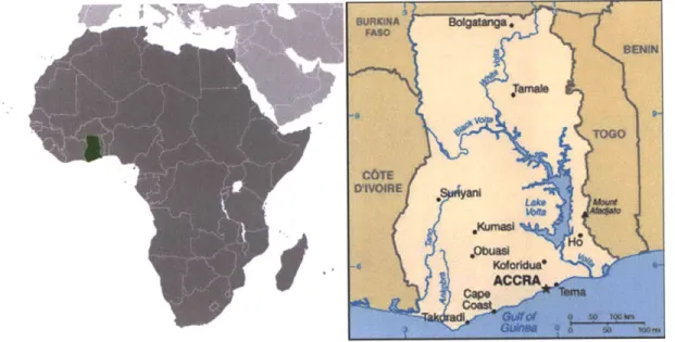
The country of Ghana in Western Africa is highlighted in Figure 1-2. It possesses a tropical climate, a population of 23.9 million, and a land area (239,460 km2) slightly less than that of Oregon (Central Intelligence Agency [CIA], 2009).
Figure 1-2: Map of Africa (Left); Map of Ghana (Right) (CIA 2009)
1.2.1.1 Under-Five Mortality
As of 2006, the United Nation's International Children's Fund (UNICEF) estimates Ghana's under-five mortality rate at 120 deaths per 1,000 live births - the 3 2"d highest in the world
(UNICEF, State of the World's Children, 2007, p. 113). According to 2003 statistics, an estimated 12% of deaths under five in Ghana are due to diarrheal diseases (WHO, 2006). As mentioned in Section 1.1, diarrheal diseases are strongly correlated to unsafe water supply, inadequate sanitation, and hygiene.
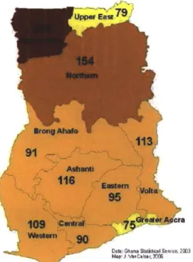
The country is divided into ten administrative divisions known as Regions (CIA, 2009). In the Northern Region - the area of focus for this thesis - the under-five mortality rate is significantly higher than the national average, at 154 deaths per 1,000 live births. Were the Northern Region its own country, its under-five mortality rate would be the 19 highest in the world (UNICEF, 2007, p. 113). Figure 1-3 presents a graphical representation by region of the under-five mortality rates in Ghana.
Figure 1-3: Under-Five Mortality Rates Per 1,000 Live Births in Ghana, 2003: (Van Calcar, 2006, p. 17)
1.2.1.2 Drinking Water Coverage
Given WHO's estimate that 12% of Ghana's under-five deaths are attributable to diarrhea, and Nash, Bloomfield, and Jones's estimate that 88% of diarrheal deaths are attributable unsafe water
supply, inadequate sanitation, and hygiene, data pertaining to Ghana's water supply coverage is of interest. As of 2006, 29% of rural Ghanaians still lacked access to improved water sources (WHO/UNICEF, 2008, p. 45). Table 1-1 describes the distribution of drinking water access in Ghana in more detail.
Table 1-1: Drinking Water Coverage in Ghana, 2006
Connection
Rural 71% 4% 67% 29%
(Adapted from W'HO/UNICEF, 2008, p. 45)
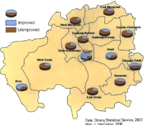
As of 2003,2900,000 of the 1.8 million people living in Ghana's Northern Region lacked access to improved water sources (Ghana Statistical Service, 2005). Figure 1-4 provides graphical information as to the distribution of improved and unimproved water access in the Northemn Region.
Data: Ghana Statistical Seivice, 2003 Map: J. VanCalcar, 2006
Figure 1-4: Percentage Use of Improved and Unimproved Drinking Water Sources in the Northern Region of Ghana (Van Calcar, 2006, p. 25);
1.2.1.3 Unimproved Water Quality
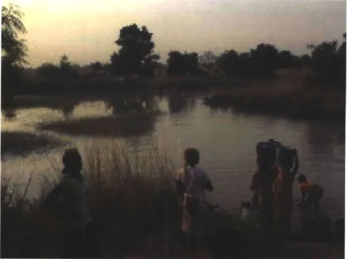
For those Ghanaians using unimproved water sources, it is useful to have an idea of the quality of their water. For many residents in the Northern Region, the water source is simply a dugout4 of the kind pictured in Figure 1-5.
4 "Dugout" is a term used locally in Ghana to refer to either (1) a pit dug into the ground for the collection of rainwater, or (2) a dammed reservoir for the storage of rainwater and streamwater.
Figure 1-5: Women at the Taha Dugout, Northern Region, Ghana Murcott provides the following data, presented in Figure 1-6, for E. coli contamination in selected Ghanaian dugouts:
Figure 1-6: E. coli Contamination in Selected Ghanaian Dugouts, 2006 (Adapted from Murcott, 2009)
For purposes of comparison, the bottom boundary of WHO's water quality risk levels are
graphed along with the measured data (WHO, 1997). One sees that all dugouts except Libga and Diare are classified, at best, as high risk.
1.2.2 Pure Home Water
To combat the lack of safe drinking water in Northern Ghana, Susan Murcott, Senior Lecturer at the Massachusetts Institute of Technology (MIT) founded the non-profit organization Pure Home Water (PHW) in cooperation with local Ghanaian partners in 2005 (Murcott, 2009). The
organization has two stated goals:
1. Provide safe water via household drinking water treatment and safe storage products to Ghanaians in need of safe drinking water, with special emphasis on the region of Northern Ghana.
2. Become locally self-sufficient and financially self-supporting.
(Pure Home Water, 2009) During its first five years, PHW focused on distribution, training, and monitoring of CPFs. In order to more efficiently meet its stated goals, PHW has decided to pursue the local manufacture of CPFs as well. 10000 1000 -a E 8100 . 0 LA. 1-U;
... Intermediate Risk w High Risk - *Very High Risk i Low Risk
0
1.2.3 Ceramic Pot Filters
1.2.3.1 A Brief History of the Ceramic Pot Filter
The dissemination of CPFs was set in motion in 1998, when a non-profit organization known as Potters for Peace (PFP) adopted a filter invented in 1981 by Dr. Fernando Mazariegos of the
Central American Industrial Research Institute (Potters for Peace, 2006). At this time, the general filtering capability of ceramics was well known; The Royal Doulton Company has been manufacuring ceramic candle filters since John Doulton first built a stoneware unit with a clay filter element for Queen Victoria in 1835 (DoultonUSA, 2010). However, the CPF was a definitive innovation in terms of cost, ease of use, and potential for local production almost anywhere in the world. When Hurricane Mitch hit Central America in 1998, PFP initiated the Filtron workshop in Nicaragua for the production of Mazariegos's filters (Potters for Peace, 2006). Since then, at least 35 filter factories have been established in at least 18 different countries worldwide (Rayner, 2009, p. 55).
1.2.3.2 The Kosim Ceramic Pot Filter
Each country has its own version of the PFP filter. The model adopted by PHW is known locally as Kosim - a word which in the Northern Region's Dagbani language means "water from a ceramic pot" and "the best water" (Ziff, 2009, p. 18). Figure 1-7 contains photographs of the Kosim filter produced by Ceramica Tamakloe Ltd. in Accra, Ghana.
Figure 1-7: The Kosim Filter: Complete Unit at Left (PFP ctd. in Fitzpatrick, 2008); Ceramic Element at Right
The filter's lip rests on the plastic ring which fits snugly over the rim of the plastic storage receptacle. Water is poured into the CPF from above. The lid is then placed on top of the ring to prevent contaminants from entering the filter. The water then seeps through the CPF and into the
1.2.3.3 Manufacture and Mechanisms of Filtration
In order to understand the mechanisms of filtration of the CPF, one must understand its
composition and manufacture. Methods of manufacture differ from country to country, but the essentials remain the same. At the PHW factory in Ghana, which began producing its first filters in January, 2010, crushed clay is mixed with a burnout material (e.g., rice husk or sawdust), wedged into cubes, and pressed in a nylon mold using a hand-cranked portable PFP press. PHW also has the capability of producing filters using the press-and-mold designed and built by Emmanuel Hernandez, often referred to as the "Mani Press." After drying, the pots are loaded into a kiln and fired, at which time the burnout material combusts, leaving pores in the CPF. It is these pores which constitute the mechanical component of filtration.
The pores trap contaminants through the phenomena of mechanical screening, sedimentation, and adsorption (van Halem D. , 2006, p. 14).
1. Mechanical screening refers to the straining of particles which are too large to pass through the pore channels created by the burnout material (van Halem D. , 2006, p. 14). Potters for Peace has selected 1 prm as their desired pore diameter (Alethia
Environmental, 2001 a, p. 19).
2. Sedimentation refers to the deposition of particles on the interior walls of the filter (van Halem D. , 2006, p. 14)
3. Adsorption is the phenomenon wherein Van der Waals' forces, which arise from nuclear attraction between particles, and/or electrostatic attraction between opposing electrical charges, cause contaminants to adhere to the surface of the pore channels (van Halem D. , 2006, p. 14).
Once the filters have been fired and cooled, they are submerged in a solution containing colloidal silver. The colloidal silver coats the surface of the pore channels and chemically alters microbial and viral contaminants. The biocidal properties of silver have long been known, but their
mechanisms of action have only come to light more recently. A few of the known biocidal interactions of silver are:
1. Removal of hydrogen atoms from thiol groups of bacteria and viruses. Thiol compounds are defined by their functional group, which contains a sulfur-hydrogen bond; once the hydrogen is stripped, sulfur atoms join one another and inhibit respiration;
2. Inhibition of DNA replication by interference with DNA unwinding; 3. Alteration of bacterial membranes via interaction with enzymic proteins
1.2.3.4 Pure Home Water's Selection of the Kosim Filter
PHW chose the Kosim filter as its primary water treatment product for several reasons.
" The effectiveness of silver-impregnated CPFs has been well-documented. Studies have shown an E coil removal efficiency of 97.8 to 100% in laboratory settings (Johnson, 2004, p. 3; Oyanedel-Craver and Smith quoted in Kallman et al., 2009, p. 21; UNICEF, 2007, p. 4).
" Use of the filters has been positively linked to a reduction in incidences of diarrhea. In Cambodia, for example, follow-up monitoring revealed that households using the filter reported only half the cases of diarrhea as compared with control houses not using the filter (UNICEF, 2007, p.4). In the Northern Region of Ghana specifically, Sophie Johnson found that people living in traditional households with filters had a 69% lower risk of diarrhea than people in households without the filters (2007, p. 3)
" The CPF can be manufactured almost entirely from local materials. All of the filter's elements are made in Ghana, with the exception of the imported spigots and colloidal silver solution (Fitzpatrick, 2008, p. 19).
* Water is already universally stored in large clay vessels in Northern Ghana, making the CPF a culturally acceptable technology (Murcott, 2009).
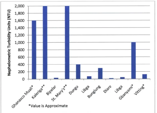
" Ghana's widely used surface water supplies are extremely turbid; CPFs are one of the few feasible technologies that can filter high-turbidity water. Figure 1-8 presents
turbidity data, obtained using a turbidity tube, from selected dugouts in Northern Ghana. For purposes of comparison, WHO suggests a guideline value of approximately 0.1 Nephelometric Turbidity Units (NTUs) for effective disinfection (WHO, 2008, p. 219).
2,000 1,800 -z 1,600 - -S 1,400 - ___ - -- - - __ - _ - -_ _ _ --1,200 - - ---1,00 - - --.1 800 - - -.i I600-4oo --0 -Z 400 - _ ___ * 200 - - ___ z 0 *Value is Approximate
Figure 1-8: Turbidity in Selected Ghanaian Dugouts: (Adapted from Murcott, 2009)
1.3 Research Objectives
Though the Kosim filter has proven itself to be an appropriate, effective, and affordable method of water filtration in Ghana, it is not without its drawbacks. One complaint commonly lodged by users is that the filters are fragile. In some sense, this is unavoidable; the filters are effective precisely because they are highly porous - a feature which renders them subject to breakage. There are, however, parameters that may be altered within the limitations imposed by the necessity of the filter's porosity that may yield increases in the filter's durability.
The objective of this research is to determine the nature and extent of the effect of compositional and geometrical changes in the Kosimfiter to its durability, specifically measured as bending strength. Recipes will be rank-ordered according to statistically significant comparative strength differences. This ranking will be included in a decision matrix along with rankings offow rate and removal efficiency from a parallel study by Miller such that an optimum recipe may be selected. The desired outcome is afilter recipe and geometry which will produce filters with decreased rates of in-use breakage while maintaining
2 Previous Research On Breakage
Though an impressive volume of literature exists regarding the flow rate and pathogenic removal efficiency of CPFs (Bloem, van Halem, Sampson, Huoy, & Heijman, 2009; Alethia
Environmental, 2001a; Leftwich, Yakub, Plappally, Soboyejo, & Soboyejo, 2009; Oyanedel-Craver & Smith, 2008), the literature on breakage of the filter is comparatively sparse. What literature exists focuses primarily on rates of breakage, rather than mechanisms or prevention of breakage. Even with this paucity of literature, however, the problem of breakage has proved ubiquitous.
2.1 Nicaragua
Concern for breakage of the filters first appears in Lantagne's field investigations in Nicaragua, published in 2001. Lantagne first mentions focus group meetings performed by students from Tulane University in 2000 in the communities of Ocotal, Matagalpa, and Malacotova. Students discovered a use rate of only 20% in Malacotova, which they partially attributed to leaking from the bronze spigots. The students recommended the establishment of a spare parts facility in each community for the replacement of broken filter elements (Alethia Environmental, 2001b, pp. 34-35).
In a separate field study performed by Lantagne, 33 homes were visited, spanning seven communities in three geographical locations of Nicaragua. Lantagne found that "Of the 33 houses visited, nine were not using the filter. The most common reason (6 homes) was that the filter or the filter and receptacle were broken" (Alethia Environmental, 2001b, p. 47). Lantagne implicitly identified the mechanism of impact as one cause of breakage, stating that homes in Mancotol used metal wire to secure their filters to the wall. Lantagne explicitly identified breakage around the lip of the filter and leakage around the filter's spigot as other causes for disuse, stating: "The most common problem seen was breakage of the filter, the receptacle, and the lip of the filter. In addition, leakage from the spigot was noted" (Alethia Environmental, 2001b, p. 55). Though breaking the lip does not always destroy the pot, it does create an avenue for untreated water to bypass the filter and contaminate the stored water, as well as causing possible cracks in the side of the filter for additional bypass (Desmyter, Adagwine, Ibrahim, Jackson, & Murcott, 2008, p. 17). Lantagne provides the following remedial recommendation: "Filters are ceramic, and as such break. Purchasing [an] extra filter at the beginning will allow for replacement of broken filters" (Alethia Environmental, 2001b, p. 56).
2.2 Cambodia
Following Lantagne's 2001 reports, UNICEF published a field note concerning the use of CPFs in Cambodia. In 2006, follow-up studies were performed on 506 randomly selected homes out of the 2000 households that had originally received the filters, some time between 0 and 44 months before initiation of the study (UNICEF, 2007, p. 3). Three-hundred fifty filters were found to be no longer in use; 328 households provided responses when asked why their filter was no longer in use. UNICEF found "A total of 214 (65%) were due to filter unit breakage, either of the ceramic filter element, the spigot, or the container" (UNICEF, 2007, p. 16). UNICEF continues: "[A] predicted 2% of filters may fall into disuse each month after implementation due primarily to breakage" (2007, p. 26), and mentions this to be consistent with a study performed in Bolivia by Clasen, et al., which found a 20% decline in use after nine months (UNICEF, 2007, p. 27). UNICEF's suggested remedy is the availability of replacement parts. To wit: "As units are subject to breakage over time, replacement parts and units are needed" (UNICEF, 2007, p. 34).
2.3 Research by van Halem
Breakage of the filter is also mentioned qualitatively in van Halem's extensive master's thesis from Delft University: Van Halem stated that, while the chances of breakage are minor for a filter remaining in its receptacle, "... [S]ince the lip is fragile and when handling the element this
lip is used for carrying etc., breakage of the lip is usually the case after several cleaning sessions" (van Halem D. , 2006, p. 59). Furthermore, van Halem opined that the filter is more vulnerable when wet, which would of course be the case during cleaning (2006, p. 59). Finally, van Halem expressed concern as to cracks in the filter element, which, if unnoticed, may create an avenue for passage of pathogenic microorganisms (2006, p. 59). Van Halem recommends frequent, thorough inspections as an appropriate preventative measure (2006, p. 59).
2.4 Ghana
Most germane to the Ghanaian context is the 2007-2008 assessment by Desmyter, et al., in which follow-up evaluations were performed on 1,000 out of the 5,000 Northern Ghanaian households to receive the Kosim CPF in response to the September 2007 floods. Desmyter, et al.'s 2008 report found that, three to seven months after implementation:
* 12% of the filters were no longer in use because of a malfunctioning filter (p. 1); 0 95% of all breakage occurred in the household (p. 1);
e the weakest spot is the lip (p. 17);
e leakage occurs when the tap is incorrectly inserted in the perforation of the safe storage container (p. 17); and
* most CPF units malfunction because they are not properly handled, while marginally few malfunction due to fatigue failure (p. 18).
Figure 2-1: Ghanaian Filter with Broken Lip (Murcott, 2009)
Figure 2-2: Ghanaian Filter with Presumed Impact Breakage (Murcott, 2009)
In light of their findings, Desmyter, et al. recommend prevention as the primary method of decreasing filter breakage: "The best approach for prevention is definitely to deliver a relevant and comprehensible education and practical training to the person who will control the ceramic filter unit" (2008, p. 18). The researchers do, however, mention that the filter may be made stronger by increasing its thickness from /2" (12.7 cm) to %" (19.1 cm) (2008, p. 19).
Furthermore, Desmyter, et al. acknowledge that some breakage is inevitable, and suggest that repair services be made available so that households may resume use of their filters as quickly as possible (2008, p. 18).
Much of the literature discussed thus far focuses on remedial action that may be taken after breakage of the filter. Barbara Donachy, former US Coordinator for Potters for Peace, provided several suggestions for preventing the filter from breaking:
* thicken the lip, from %/2" (12.7 cm) to %" (19.1 cm)
* provide a gasket between the ceramic filter and the storage container for prevention of failures that occur upon removing a stuck filter from an improperly sized storage container
e increase focus on quality control to guarantee adherence to existing guidance
3 Modeling the Filter
3.1 Potential Failure Mechanisms
As mentioned, very little research exists relating to the failure mechanisms of the CPFs.
However, in a series of e-mails with Mary Kay Jackson, Managing Director of PHW in Ghana, three failure mechanisms were mentioned. Additionally, Section 2.4 mentions the identification of fatigue failure by Desmyter, et al (2008).
3.1.1 Impact Failure
In an e-mail from Mary Kay Jackson dated November 21, 2009, she mentions: "[W]e see impact failures due to either mishandling or more brittle clays." This confirms Lantagne's suggestion of impact breakage mentioned in Section 2.1. Thus, improving the impact strength of the filter may decrease the rate of breakage.
3.1.2 Shear Failure
In an e-mail dated November 22, 2009, Ms. Jackson wrote: "The lip failures generally seem to be shear failures early in the life of the pot," and "Pots are shipped in a stack of [three], and we would break pots just when pulling them apart." Desmyter et al. confirm that "Lip breakage usually happens when the ceramic pot is not gently handled or can occur when it is lifted out of the safe storage container while it is filled with water (2008, p. 17). Based on this testimony, investigation of shear strength may be informative for providing recommendations to prevent future breakage.
3.1.3 Bending Stress Failure
Ms. Jackson also wrote in her November 22, 2009 email that "... [I]t may be necessary to increase the lip's thickness as well to overcome the bending stress of lifting." As referenced in Section 2, Lantagne, Desmyter et al., and van Halem have all mentioned failure of the lip without specifying the mechanism of failure, but lifting the filter by its lip undoubtedly places both bending and shear stress on the filter, as will be shown in Section 3.2. Therefore, data from bending stress testing is of interest.
3.1.4 Fatigue Failure
Desmyter et al. mention that "[M]arginally few" filters fail due to fatigue (2008, p. 18).
However, the failures described by Ms. Jackson all occur well before fatigue failure becomes an issue. It is therefore more critical to address impact, shear stress, and bending stress failure, which render filters useless or less effective soon after their manufacture.
3.1.5 Selection of Failure Mechanism for Investigation
Due to constraints of time, money, and equipment, not all potential failure mechanisms could be investigated within the scope of this thesis. Inferences were made in the hopes of selecting the
failure mechanism whose investigation via material and geometric changes would be most likely to yield strength increases which could be realized with the resources currently available to PHW. Through conversations with Dr. Krystyn Van Vliet, MIT Associate Professor in the Materials Science Department of the Massachusetts Institute of Technology, and Dr. Tomasz Wierzbicki, MIT Professor of Applied Mechanics in the Department of Mechanical Engineering at the Massachusetts Institute of Technology, bending stress was determined to be the most promising mechanism of failure for investigation.
3.1.5.1 Dismissal of Investigation of Impact Failure
In addition to an investigation of bending stress failure, the American Society of Testing and Materials (ASTM) provides ASTM C368-88, Standard Test Method for Impact Resistance of Ceramic Tableware, which seems an appropriate method for investigating the impact strength of CPFs under their normal loading conditions. In this test, the rim and center of ceramic pieces are subjected to a schedule of impacts so as to determine the magnitude of the blow required to cause initial fracture and the amount of energy necessary to cause complete failure of the sample. Unfortunately, no apparatus meeting the specifications described in the standard was available. Although such an apparatus could have been manufactured, constraints of time and money forbade such an endeavor.
3.1.5.2 Dismissal of Investigation of Shear Failure
Tests for the shear strength of a material are difficult to design. ASTM does not provide a loading configuration that will place a ceramic material in pure shear, i.e., shear force without moment force. Furthermore, Dr. Wierzbicki suggested that the performance of a bending-stress test would be sufficient for rank-ordering the strength of the material, and further testing on impact and shear failures would neither affect the rank-ordering nor provide useful additional information (personal communication, December 2009). Thus, investigation of shear failure was not pursued.
3.1.5.3 Investigation of Bending Stress Failure
As mentioned, bending stress failure was determined to be the most promising mechanism for investigation. The author patterned the selected test method after ASTM C674-88, Standard Test Method for Flexural Properties of Ceramic Whitewares.' The details of the employed test method are presented in Section 4.5
3.2 Modeling Stresses in the Lip of the Ceramic Pot Filter 3.2.1 Measurement of Dimensions
In order to model the bending stress in the lip, one must obtain dimensions of the CPF.
Investigations on a fractured pot from the PHW factory in Tamale, Ghana, are included in Figure 3-1 and Table 3-1. The methods of measurement are detailed in APPENDIX A.
The measurements with asterisks were obtained from AutoCAD 2010© rather than from direct measure. In fact, if only measurements obtained from direct measure had been used, a
symmetrical, geometrically consistent pot could not be produced, due to the variation in the measurements and the warping of the pot. Thus, a set of minimum requisite measurements was employed.
It should be noted that PHW also has the capability of producing a paraboloid-shaped filter from the aforementioned Mani Press. The author has not recorded dimensions of or modeled forces
on the paraboloid filter. However, the rank-ordering of material compositions based on bending strength and the bending strength gained from geometrical variations in the lip will apply to filters of any shape. Statements about the expected stresses experienced by the lip, however, apply only to the flower-pot shaped filter.
5 "Whiteware" refers to a broad class of ceramic products, including earthenware such as the CPF (Whiteware,
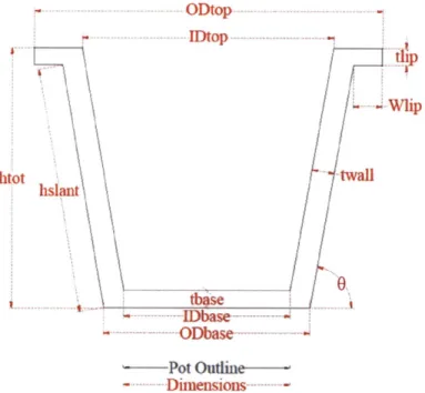
ODtop IDtop dp .Wlip htot twall hislant Itbase - ODbase-'-Pot Outine-- Dimensions
-Figure 3-1: Diagram of the PHW Filter from Tamale, Ghana
Table 3-1: Measurements of the PHW Filter from Tamale, Ghana
22.2cm IDa,, 14.7cm t",* 2.0cm htt* 22.7cm Wi- 2.5cm *Obtainedfrom AutoCAD 2010C
Van Halem has provided a similar set of measurements for the Ceramica Tamakloe Ltd. filter, a Cambodian filter, and a Nicaraguan filter (2006). These measurements have been adapted and included in APPENDIX B.
3.2.2 Modeling of Loading Condition
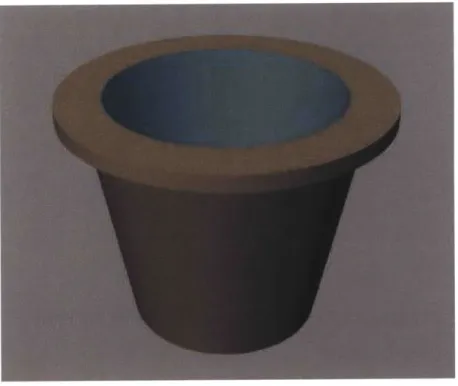
Now, one wishes to model the forces experienced by a filter when lifted by its lip. First, consider a rendering of the CPF carrying its full capacity of water in Figure 3-2 below.
Figure 3-2: Rendering of Pot with Full Water Load
Now consider an infinitesimally thin cross-section of the filter. We may quantify the weight forces acting on this cross-section per unit length and unit depth by considering the density of the pot, the density of water, and the vertical extent of each substance at each position on a
horizontal x-axis. The scenario is depicted in Figure 3-3.
1Po 1 O IttuI
j
i
Wet Po od --WAter
Loud---Figure 3-3: Loading Condition of Ceramic Pot Filter
Two separate loads are represented: 1. the load due to the wet pot, and 2. the load due to the contained water.
Notice that the wet pot load changes as one traverses the filter wall; this is due to the fact that a vertical line through the pot intersects first an increasing portion of the filter's wall, then a constant portion, then a decreasing portion until only the base is intersected. Similar arguments apply for the water load. The arrows representing the load forces have been scaled such that their relative lengths represent the relative magnitudes of the loads.
Forces located at any radius r from the center of the filter are equal. Thus, the sum of the moments about any axis that is perpendicular to the direction of the application of the forces and that intersects the filter's center is zero. We may then resolve the forces into two weight loads, equal to the sum of the weight loads contributed by the pot and its contained water, acting perpendicular to the plane of the filter's base and through the center of the filter's base. The situation is depicted in Figure 3-4.
I It
Pot utIm
Wet Pot Load
-Wae
Lad-Figure 3-4: Resultant Weight Forces Acting on the Ceramic Pot Filter
Hidden lines have been added to emphasize that one is now looking at an elevation view of the pot, not an infinitesimal cross-section - the resultants include the contribution from the entire wet pot load and the entire water load, not the contribution from an infinitesimally thin cross-section alone.
One wishes to determine the magnitude of these loads. Now, it is well known that W=pgV, where p is density, g is the acceleration due to gravity, and Vis volume. The volume of the pot and its contained water were obtained from AutoCAD 2010C and geometry, respectively. The density of water is well-known for given temperatures; one will assume room temperature (250
C) for this calculation. The dry density of each pot was obtained by averaging the mass of 26 CPFs produced at the PHW factory in Tamale, Ghana and dividing by the volume obtained from AutoCAD 20100. The wet density is related to the dry density by:
Pwe MotWet n(V)(pat) + Pot,Dry
V V
Equation 3-1 where n is the porosity of the pot. One may adapt an average porosity of 0.38 from the measurements of Van Halem (2006, p. 17).
The weights and associated parameters are presented in Table 3-2.
Table 3-2: Density, Volume, and Weight of Wet Ceramic Pot Filter and Contained Water
IV 3,500cm' 5,700cm' W 46N, 5-'.
When supporting the pot with one's hands, the entire weight of the pot and the contained water must be countered by the hands' upward force. This force is modeled as a linearly decreasing
distributed load, seen in the closeup of the filter's lip, Figure 3-5.
q~.x
Figure 3-5: Closeup of Filter Lip
Notice that the intersection of the filter lip with the filter wall is modeled as a fixed support, with shear reaction force V and moment reaction force M. The arrows representing the magnitude of the hand load, shear reaction force, and moment reaction force are not to scale. The distributed load representing the self-weight of the wet pot has been neglected; this is a conservative
assumption, as it creates a larger moment, and is a reasonable simplification, given that the self-weight of the lip is small compared to the hand load.
The choice of the linearly decreasing load as a model for the upward force provided by a lifting hand is predicated on the idea that a person lifting the filter will exert more force on the outer
edge of the lip than on the inner edge. Furthermore, this loading is conservative in that it creates a greater moment force than either a uniform or linearly increasing load, since the majority of the force is concentrated away from the fixed support.
For simplicity of calculation, we may resolve the distributed load into its resultant force, which maintains the condition of equilibrium without changing the value of the moment at the fixed support. The resultant of a distributed load acts through the centroid of the area of the
distribution, which, for a triangle, is located at two-thirds of its height. For the orientation presented in Figure 3-5, the resultant acts at location x = W1 1'3, as depicted in Figure 3-6
I )1 II
Pot Outlmae Wet Pot Load -Water
Lead---A
LOd---Figure 3-6: Resultant Forces Acting on Ceramic Pot Filter in Equilibrium Because the resultant hand load must balance the resultant weight loads from Figure 3-4, one wntes:
J F ~~F ~k+(Wwetpot+WWater2HO+ =
(w,,
+ W,, )- 2H = 0 ,Equation 3-2 where H is the resultant force of the hand load. This may be rearranged as follows:
H = WetPot + WWatr
2
Equation 3-3 From the values listed in Table 3-2, one finds H = 51 N, and all resultant values of the loading
condition have been determined.
3.2.3 Calculation of the Maximum Bending Stress
Modeling the forces as a linearly decreasing distributed load allows one to determine a function for the maximum moment experienced by the lip of the filter, which occurs at the fixed support:
qW2
Mmar :::::max ip "3
Equation 3-4 This result is derived in APPENDIX C.
Now, H is equivalent to the area under the curve of the distributed load, which, for the triangle, may be written:
A = H a Wl
2
Equation 3-5 One may rearrange this equation as follows:
2H
qmax - li
Equation 3-6 Substituting Equation 3-6 in Equation 3-4 yields:
2 H (W,,, 2
max = (- HWii
W,,, 3 3
Equation 3-7 Substituting Equation 3-3 for H in Equation 3-7 yields:
Mmax = 2 (Wtp, + Wwater,)Wli W,,,,,, + Wwat"r Wji
Equation 3-8 The hand will act over a portion of the filter's circumference. Continuing to model this portion of the filter as a cantilevered beam, one may assign the beam a dimension, c, equal to the portion of the filter's circumference over which the hand acts. The extent of this dimension will be equal to the width of the four fingers used in lifting the pot; this width has been taken as equal to the width of the author's four fingers, which is approximately 5cm. The beam is depicted in Figure 3-7.
Figure 3-7: Extracted Cantilever Beam From Lip of Ceramic Pot Filter (dimensions in cm) A further assumption has been made in considering a rectangular beam to be a good
approximation to a beam arising from the filter's true geometry.
The testing procedure will yield data as to the modulus of rupture of the various materials. The modulus of rupture is a material property which describes the greatest bending stress that a material can withstand under bending before it ruptures. Moment and bending stress in beams are related according to the following equation:
-MyC IX,
Equation 3-9 where:
a is the stress at yc M is the applied moment
yc is the distance from the y-coordinate of the beam's centroid to the position at which a is considered, and
I, is the moment of inertia of the cross-section about its centroidal x-axis. The negative is a sign convention indicating that the beam experiences:
* compressive stress, considered negative, at locations above the centroid, where yc is positive, and
In this analysis, one is concerned primarily with the magnitude of the stress; thus the negative sign will be removed in subsequent equations.
For a rectangular cross-section, the y-coordinate of the centroid is located at the midpoint of the cross-section. For purposes of this analysis, one will concern oneself with the maximum moment, which occurs when y, is greatest, i.e., at the outermost fiber of the beam. At this location, y, equals one-half the thickness, t, of the cross-section. That is:
t YC =-,
2
Equation 3-10 The moment of inertia about the horizontal centroidal axis, x', is:
12
Equation 3-11 where w is the width of the cross-section. In subsequent equations, w will be replaced with c, the portion of the filter's circumference over which a lifting hand acts.
Substituting Equation 3-10 and Equation 3-11 in Equation 3-9 yields:
t
amax -_62 12
Equation 3-12 where the subscript max indicates that one is considering the maximum value of compressive stress by choosing the maximum value of yc.
One may replace M in Equation 3-12 with Mmax from Equation 3-8 to determine a formula for the maximum bending stress expected in the lip of the CPF.
6 'W,,,o, +W"'Wut
max - ~W 3 W 2(Wtpt + WWat,,
Ct2 C2 W
Equation 3-13 Replacing now all of the variables in Equation 3-13 with the known values from Table 3-1 and Table 3-2, and letting c = the approximate width of the fingers used to lift the pot (5cm), one may obtain the maximum bending stress that the lip of a full filter must endure as:
amayfull = 0.45MPa
Equation 3-14 If this value exceeds the modulus of rupture, R, calculated from the test procedure described in
Section 0, one predicts that a filter manufactured in the same conditions as the test sample will break if lifted while carrying a full load of water.
If one omits the water weight, one may obtain the maximum stress endured by the lip of the filter while carrying only its wet self-weight:
umaempty =0.20MPa
Equation 3-15 If this value exceeds the modulus of rupture, R, calculated from the test procedure described in Section 0, one predicts that a wet filter manufactured in the same conditions as the test sample will break if lifted while empty.
3.2.4 Calculation of the Maximum Shear Stress
It is now a trivial matter to calculate the maximum shear stress experienced by the filter. Shear stress is defined as:
P
o = -,
Equation 3-16 where P is the load acting parallel to a plane of cross-sectional area A. For the beam of Figure 3-7:
H
VCt
Equation 3-17 Using the known values, one finds u,= 0.068 MPa for a CPF bearing a full water load and u, = 0.031 MPa for an empty CPF. The implications of the presence of shear stress will be discussed in Section 3.3.
3.2.5 Summary of Key Results
Table 3-3: Summary of Key Results for Stresses in the Lip of the CPF
3.3 Limitations to Modeling and Testing Methods 3.3.1 Neglected Shear Forces
In truth, the situation depicted in Figure 3-3 through Figure 3-5 is a simplification of the loading condition. The beam has been created by removing a portion of the pot and applying the
calculated loads. However, the removed portion of the filter would exert shear forces on the faces exposed by its removal. Figure 3-8 depicts a thin slice of the filter including the shear forces exerted by the filter's removed portion.
Figure 3-8: Rendered Strip of Pot With Shear Forces
.
This force has been neglected in the analysis; to consider it would result in a statically
indeterminate condition, i.e., a condition which results in a system of n linear equations with m unknowns, where m > n. Proper characterization of this condition requires numerical analysis
methods, in which algorithms utilizing numerical values are applied to develop an approximate solution to a continuous problem in lieu of an exact analytical solution. One method of
numerical analysis often applied to structural analysis problems is the Finite Element Method, in which a continuous member is divided into elements whose characterization generates a
deterimnate system of simultaneous equations which may then be solved to describe the stresses at any point in the member with reasonable accuracy (Cook, Malkus, & Plesha, 1989, p. 2). The development, calibration, and application of such a model is time-consuming, and such a method is beyond the scope of this research. Under the advice of Professor Van Vliet, the previously discussed simplifications were deemed to describe a reasonable approximation to the true loading condition, and were therefore employed.
3.3.2 Neglected Interaction of the Shear and Bending Forces
Dr. Wierzbicki and Dr. Connor, Professor in the Department of Civil and Environmental Engineering, have stated that shear and bending work in tandem to create failure (personal
communication, December 2009). That is, a material subjected to a shear stress of magnitude x, will fail under a bending stress of magnitude x2, while a material subjected to a shear stress of magnitude yi # x, will fail under a bending stress of magnitude Y2 not necessarily equal to x2.
The inclusion of shear stress creates an additional tensile stress on a beam element. This tensile stress is maximized on the plane angled forty-five degrees from the direction of application of the force. This tension acts in tandem with the tension created via the moment force. The interaction of the tensile stresses arising from shear and bending creates a failure envelope
detailing the combined shear and bending loads that a material can withstand; points outside of the envelope imply failure. Such an envelope is depicted schematically in Figure 3-9.
0
M,
M0
M
Figure 3-9 (Adapted from University of Ljubljana)
The bending stress test described in Section 0 is intended to place the material into nearly pure bending, i.e., into a condition in which the shear stress is too small to influence the magnitude of the bending stress at which the material will fail. That is, it attempts to place the material into a loading condition represented by the portion of the curve labeled CD, where Mpi is the maximum bending stress that the material may withstand even when the shear load is zero. One says that bending is the primary failure mechanism in this condition.
It is possible that the actual bending stress which may be withstood by the lip of the filter is less than this value obtained from testing because that the lip is subjected to both shear and bending. That is, it is possible that the actual loading condition experienced by the filter is not described by the region CD on the graph, but rather by the region BC, in which shear influences the allowable moment, or even AB, in which shear is the dominant failure mechanism. This possibility will be revisited in Section 5.3.1.2.
Proper development of this shear-moment interaction diagram is difficult, and involves fixing the bending stress while varying the shear stress, or vice-versa. Moreover, such a test would require more samples than could be feasibly manufactured, transported, and tested for this thesis.
Furthermore, because the major desired outcome of this research is a rank-ordering of the material compositions in terms of strength, and because bending strength gains/losses often accompany shear strength gains/losses, determination of whether the material will fail under ordinary loading, and by what mechanism, is of secondary concern. Dr. Wierzbicki suggested that a single configuration of the bending stress test, and a rank ordering based upon such a test, was a reasonable substitute for the full development of this curve (personal communication, December 2009).
4 Methodology
Sections 4.1 through 4.4 describe actions taken while in the field in Tamale, Ghana in order to produce samples representative of actual field conditions. These samples were then transported in carry-on luggage to MIT so as to carry out the testing described in Section 4.5, which required equipment not available in Ghana.
4.1 Method of Material Preparation
The author produced a total of 150 clay beams of unfired length 115 mm, unfired width 25 mm, and unfired thicknesses of either 15 mm, 20 mm, or 25 mm. All raw materials were obtained from local sources in Ghana's Northern Region. They included:
* Clay taken from a pit in the town of Gbalhi;
e Grog6 produced from broken PHW pots, manufactured earlier by Ceramica Tamakloe, Ltd.;
" Rice husk obtained from local farmers; * Sawdust obtained from local mills; and
" Water obtained from a dugout in the town of Taha. The material preparation process for the clay was as follows:
1. Break clay clods into small (< 5 cm diameter) pieces by hand or by hand tools.
2. Spread clay pieces on a tarp and let dry in sun for 1 to 2 days under sunny sky conditions. Samples are sufficiently dry when, if broken apart, they show no color change in their centers due to remaining moisture.
3. Pound clay to a fine powder using mortar and pestle. 4. Pour the clay powder through a 1 mm by 2 mm mesh. Figure 4-1 illustrates the steps in this process
6 grog refers to previously fired ceramic material that has been crushed to a desired particle size.
Breaking & Drying Clay Pounding Clay Sieving Clay
Figure 4-1: Steps in the Method of Clay Preparation (Photo Credit: Murcott [Far Left], Leah Nation [Center and Right], 2010)
The material preparation process for the sawdust and rice husk was as follows:
1. Place the combustible material into a 2-horsepower-engine hammermill of the kind shown in Figure 4-2.
Figure 4-2: Hammermill (Closed at Left, Photo Credit: Leah Nation, 2010; Open at Right) 2. Allow material to mill for a period of approximately one minute.
3. Collect milled material from both the waste chute, located at the bottom of the hammermill, and the radial chute.
4. If desired, sieve the remaining materials through a 1 mm by 2 mm mesh. This step was performed only for recipes #13 and #14.
4.2 Method of Mixing
Materials were hand-mixed by local potters. The recipes for each of the 14 mixes are shown in Table 4-1 below. The water content of each mixture was determined by the expert judgment of local potters, and varied for each pot produced. The water is added solely for the purpose of increasing malleability of the mixture, and is removed during the drying and firing processes. Therefore, it does not have any expected effect on the filtering ability, flow rate, or strength properties of the resultant filter.
Table 4-1: Filter Recipes (Adapted from Miller, 2010)
Rice Husk Fine and Waste Yes 11 4.00 2.00 2.00 16.00
Rice Husk Fine and Waste Yes 11
Sawdust rme ana waste
Fine and Waste
Yes 11 Yes 11 2.91 3.64 1.46 1.82 1.46 1.82 14.91 15.64
1 14 Kice Husk Fine Sieved No 11 0 2.55 2.55 0.00 13.55
4.3 Method of Casting and Drying Samples
After mixing, the samples eventually used in the bending stress tests were cast using the three molds shown in Figure 4-3.
10 12
7'
2", Sawdust fino'iW W; s* .3, "14.64 5.00 2.50 2.50 17.00 SawdustFigure 4-3: Molds For Casting Samples
Each mold has dimensions of 115 mm in length and 25 mm in width, with thicknesses of 13 mm, 20 mm, and 25 mm.
The procedure for casting and drying was as follows:
1. Begin with clean wood block, wood mold, butter knife, and SparcoTm Brand stamper. Also begin with moist clay of one of the 14 mixtures shown in Table 4-1.
2. Press clay into mold from either side, flattening with palms.
3. Use flat edge of butter knife, with fingers pressed down on either side, to screed off the excess from one side.
4. Clean the knife
5. Repeat step 3 for the other side of the mold.
6. Place the mold on a flat surface and use a wet finger to smooth the clay surface. Fill in patches if necessary by adding a dab of clay to the moist finger.
7. Flip over the mold and repeat step 6 for the other side. 8. Stamp one side of the clay.
9. Using the wood block extruder, hold the mold in the air with two hands and use thumbs to apply pressure to the unstamped side of the clay until the clay is free from the mold.