Publisher’s version / Version de l'éditeur:
Vous avez des questions? Nous pouvons vous aider. Pour communiquer directement avec un auteur, consultez la première page de la revue dans laquelle son article a été publié afin de trouver ses coordonnées. Si vous n’arrivez pas à les repérer, communiquez avec nous à [email protected].
Questions? Contact the NRC Publications Archive team at
[email protected]. If you wish to email the authors directly, please see the first page of the publication for their contact information.
https://publications-cnrc.canada.ca/fra/droits
L’accès à ce site Web et l’utilisation de son contenu sont assujettis aux conditions présentées dans le site LISEZ CES CONDITIONS ATTENTIVEMENT AVANT D’UTILISER CE SITE WEB.
The 16th International Conference on Vision Interface [Proceedings], 2003
READ THESE TERMS AND CONDITIONS CAREFULLY BEFORE USING THIS WEBSITE. https://nrc-publications.canada.ca/eng/copyright
NRC Publications Archive Record / Notice des Archives des publications du CNRC : https://nrc-publications.canada.ca/eng/view/object/?id=2318fd2b-a06f-4b45-b9ec-83a4800af82d https://publications-cnrc.canada.ca/fra/voir/objet/?id=2318fd2b-a06f-4b45-b9ec-83a4800af82d
NRC Publications Archive
Archives des publications du CNRC
This publication could be one of several versions: author’s original, accepted manuscript or the publisher’s version. / La version de cette publication peut être l’une des suivantes : la version prépublication de l’auteur, la version acceptée du manuscrit ou la version de l’éditeur.
Access and use of this website and the material on it are subject to the Terms and Conditions set forth at
Replacing a Mouse with Hand Gesture in a Plane-Based Augmented
Reality System
National Research Council Canada Institute for Information Technology Conseil national de recherches Canada Institut de technologie de l'information
Replacing a Mouse with Hand Gesture in a
Plane-Based Augmented Reality System *
McDonald, C., Roth, G.
June 2003
* published in The 16th International Conference on Vision Interface. Halifax, Nova Scotia, Canada. June 11-13, 2003. NRC 46491.
Copyright 2003 by
National Research Council of Canada
Permission is granted to quote short excerpts and to reproduce figures and tables from this report, provided that the source of such material is fully acknowledged.
Replacing a Mouse with Hand Gesture in a Plane-Based
Augmented Reality System
Chris McDonald1, Gerhard Roth 2
1 School of Computer Science, Carleton University, Ottawa, Canada, K1S 5B6 2 Computational Video Group, IIT, National Research Council, Ottawa, Canada, K1A 0R6
http://www.cv.iit.nrc.ca/research/ar
Abstract
A modern tool being explored by researchers is the technological augmentation of human perception known as Augmented Reality (AR). In this paradigm the user sees the real world along with virtual objects and annotations of that world. This synthesis requires the proper registration of virtual information with the real scene, implying the computer’s knowledge of the user’s viewpoint. Current computer vision techniques, using planar targets within a captured video representation of the user’s perspective, can be used to extract the mathematical definition of that perspective in real-time. These embedded targets can be subject to physical occlusion, which can corrupt the integrity of the calculations. This paper presents an occlusion silhouette extraction scheme that uses image stabilization to simplify the detection of target occlusion. Using this extraction scheme, the paper also presents a novel approach to hand gesture-based interaction with the virtual augmentation. An implemented interaction system is described, which applies this technology to the manipulation of a virtual control panel using simple hand gestures to simulate mouse control.
Keywords: Gesture recognition, augmented reality, virtual interface,
image stabilization, occlusion detection, computer vision.
1 Introduction
A new field of research, whose goal is the seamless presentation of computer generated information added to a user’s natural perspective of the world, is called Augmented Reality (AR) [1]. Augmented Reality is a perceptual space where virtual information, such as text or objects, is merged with the actual view of the user’s surrounding environment. This can be accomplished in a number of ways; for example, by using head mounted displays, or by looking through a liquid crystal view port. What is important is that the user be able to see both the real world, and the virtual information that is used to augment that world, and to see both at the same time. The applications of augmented reality are wide and varied, from entertainment to manufacturing to medicine [1,2,13]. In
order for the computer to generate the correct contextual information, it must first understand the user’s context. The parameters of this context are limited to environmental information and the user’s position and orientation within that environment. With such information, the computer can position the augmented information correctly relative to the surrounding environment. This alignment of virtual objects with real scene objects is known as registration. Without a good solution to the registration problem the augmented information appears at the wrong locations, or is incorrect, which destroys the impact of the AR system. Solving the registration problem robustly, accurately, and in real-time is the key research issue in augmented reality [14]. This problem has not been solved in general for an unstructured environment. For this reason, structure is often added to the environment, usually in the form of targets. The most common and successful target based AR system uses planar targets [10,8]. These targets are recognized and tracked in real-time using a standard single video camera vision system. The co-ordinate frame associated with the target provides a natural location for the augmented objects. Many applications have been built on this type of plane-based AR system [5,16,18].
Figure 1 – Augmentation on planar pattern
In order for proper tracking to occur it is necessary to compute a planar homography [19] between the detected targets in the video sequence and the stored pattern of these planar targets. This homography defines a warp from the original stored two-dimensional pattern to its location in the image frame. From this homography, the necessary
camera parameters can be extracted [15] to define a 3D coordinate system on the image-space target. This coordinate system is then used as an origin for augmenting the virtual objects. As the target and/or camera move, the homography is updated in real-time. This ensures proper alignment of virtual objects with the real scene in each frame of video.
One important capability that is missing in most AR systems is the ability to interact with virtual environment. Examples of such interaction are manipulation of common virtual representation in collaborative AR, or even more simply, the ability to change or adjust the augmentation to suit current conditions. In the vast majority of current AR systems the user is left with few mechanisms for interacting with the virtual augmentations. One option is the use of hardware devices such as gloves or touch screens [18]. While these are effective to a degree they are physically restrictive given the special freedom goals of Augmented Reality. An interesting alternative is the use of natural human gestures to communicate directly with the environment. Gesture recognition has been explored mainly for the purpose of communicative interaction. Gesture systems have explored many aspects of hand gesture including three-dimensional hand posture [5] and fingertip motion [11,17,4]. The system presented in this paper attempts to bridge these two fields of study by describing a hand gesture system that is used for manipulative interaction with the virtual augmentation. The idea is to use a planar-based AR system, and to allow the user to change or adjust the augmentation by using hand gestures directly over the pattern. In traditional pattern based AR systems when the planer pattern is occluded the augmentation process fails. In previous research [10], we describe how to extend a planar-based AR system to be able to tolerate occlusions. In this research we describe a system in which hand occlusion of the planar pattern is utilized to make it possible to interact with, and modify the augmented world.
While natural human gestures are too complex to recognize in real-time, we define a simple gesture model that allows a practical interactive medium for real-time Augmented Reality systems. These simple hand gestures enable use to simulate mouse control over a virtual control panel defined on top of the pattern. More precisely, augmentation proceeds as usual on the pattern until the hand occludes it. Then, as is shown in Figures 6 and 9 we are able to modify the interaction by for example, stopping and starting the augmentation. This is a novel approach to hand gesture-based interaction with the virtual augmentation. To our knowledge, this system, which was partially described in [9,10], is a unique in that it enables hand interaction with a planar-based AR system.
In this paper we concentrate on the details of the gesture model used for this application. In particular, we describe how we use image stabilization to detect the occluders, and then discuss the gesture model and the gesture recognition system. Our gesture system is tailored to be as simple and robust as possible, and yet still be able to duplicate the mouse operations of selecting and pointing. In other words, it is a simplified gesture model that is tailored to this application.
2 Stabilization for Occlusion
Detection
Our goal in this section is to describe how we detect the occlusion of the planar pattern in real-time. The input is the image containing the occluded pattern, and the output should be a binary image (essentially a 2D silhouette) of that pattern. This process is made more difficult because in augmented reality systems, both the camera and the target may be moving independently. To simplify the occlusion detection, the image sequence is stabilized to remove the effects of camera motion. Many camcorders use image stabilization to remove the jitter caused by camera motion during the video capture. In the context of the tracking system described in [10], stabilization is performed on the captured image relative to the original stored target pattern. This effectively removes both the rotational and translational motion of the camera, enabling image subtraction for occlusion segmentation.
2.1 Image Stabilization
Image stabilization is a technique used to remove the effects of camera motion on a captured image sequence [3]. Stabilization is normally performed relative to a reference frame. The effect of stabilization is to transform all the image frames into the same coordinate frame as the reference, effectively removing camera motion. When the reference frame contains a dominant plane, the stabilization process is simplified. In order to stabilize, it is first necessary to track planar features from frame to frame in the video sequence. From these tracked features it is possible to construct a frame-wise homography describing any frame’s transformation relative to a reference frame. In terms of this system, pattern space is defined by the corner feature positions of the front-facing original pattern, and this remains fixed. Each captured video frame describes a new position of the pattern in image-space. Therefore for each such frame a new homography is computed to describe the relationship between the pattern positions in the two spaces. The constant nature of pattern-space implies that if the inverse of this homography is applied to the captured image, then this image will be stabilized. In effect, the camera motion can be removed
from all the frames in the AR video sequence by applying this inverse homography transformation. Figure 2 shows the stabilization (b) of a captured image frame (a) relative to the detected target.
(a) (b)
Figure 2 – (a) Captured video frame (b) Stabilized representation relative to the target
2.2 Occlusion Extraction
With a stabilized image, the problem of occlusion extraction can be reduced to image subtraction and segmentation. Image subtraction is the computed pixel-wise intensity difference between two images. This technique is commonly used to detect foreground changes relative to a stationary background in a video sequence. This form of image subtraction is referred to as background subtraction. An image, known to contain a stationary background, is stored and used as the reference image in the subtraction algorithm. Assuming a fixed camera position relative to the scene background, any significant pixel differences will indicate the introduction of one or more foreground objects, which in our context are the occluders.
The subtraction process computes the absolute difference between the stabilized image frame and the original pattern. Figure 3 shows an example of the difference image (c) associated with the given stabilized image (a) and pattern (b). Here there are no occluders, and any differences are simply due to lighting variations, or slight errors in the computed homography.
(a) (b) (c)
Figure 3 – (a) Stabilized image frame (b) Original pattern (c) Absolute difference image
The next step in the extraction process is image segmentation. Image Segmentation is the process of separating regions of varying intensities in order to isolate
certain regions of interest in the image [7]. In this case, the goal is to segment or find the occluders in the subtracted image. The particular segmentation algorithm used to achieve this goal is called binarization. It takes the difference image, which is a grey-scale image, and transforms it into a binary image. There are many binarization algorithms, and we choose a simple fixed threshold binarization algorithm. A fixed Binarization threshold value is chosen to suit the current lighting conditions of the captured scene and is used throughout the image sequence. This process segments the image into two distinct regions, one representing the occlusion and the other representing the un-occluded portions of the stabilized target.
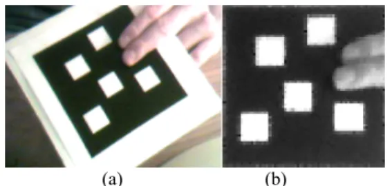
In order to analyze the characteristics of the current occlusion, the occluder has to be extracted from this binary image and stored in a tangible form. The extraction process scans the binary image in order to build a more useful representation of the occluders. Although the binary image contains mainly occlusion pixels, there exist spurious pixels that correspond to camera noise and pixel intensities that fluctuate near the threshold boundary. In order to gather only the pixels of the occluders, a connected region search is performed. The result of this process is a group of connected binary pixels, called a binary blob, that represent the occluder. All blobs containing more than 60 pixels are considered to be valid occluders. Figure 4 shows the binary blob computed from the stabilized image in figure 2(b).
Figure 4 – Binary blob of stabilized target occlusion
3 AR Interaction through Gesture
Once the captured video frame has been stabilized and occlusion has been detected and defined in terms of binary blobs, the interaction problem becomes one of gesture recognition. As described in section 2, target occlusion is detected and defined relative to the target plane. Since all virtual augmentation is defined relative to the target plane, interactivity between real and virtual objects can occur within this common coordinate system. The following section describes a hand-based interaction system using gesture recognition. Our goal is to provide the simplest gesture recognition system for two-dimensional manipulative interaction similar to the common mouse.Currently, using a mouse to manipulate a window interface is commonplace. Our system provides a mouse-like gesture based interface to an immersed AR user without the need for the cumbersome mouse. To simulate a mouse requires the recognition of both point and select gestures in order to generate the appropriate mousedown and mouseup events at the indicated location. This goal is achieved without the need for a sophisticated gesture recognition system such as [11] involving complex finger tracking for gesture inference through motion. Instead, the gesture model is specialized for the task of mouse replacement. Performing the gesture analysis in pattern-space simplifies the image processing and creates a very robust gesture recognition system.
3.1 Gesture Model
In order to define an appropriate set of gestures, the requirements of the application must be well defined. The requirements of our gesture system are as follows: real-time system performance, the use of commercial PC and camera hardware, and hand-based interaction without hardware or glove-based facilities.
The real-time requirement of the system poses great restriction on the level of gesture recognition that can be implemented. Commercial hardware may also limit system performance, as well as limit the quality of image capture on which all computer vision-based, image analysis techniques rely. The third requirement forces the use of computer vision to recognize hand gestures, which is performance-bound by the processor. The approach used has been formulated to satisfy the requirements event with these restrictions.
The goal of this interaction system is to provide the user with a virtual interface to control the augmentation system properties. In other words, the goal is to allow the user to change system parameters through manipulative gestures in real-time. The interface is designed to be a control panel that is augmented on the planar pattern. The user should be able to interact directly with this augmented control panel on the 2-dimensional planar pattern. This allows the user to directly manipulate the set of controls provided on the panel. The original 2-dimensional planar target can be fixed in the environment or carried by the user and shown to the camera when the interaction is desired. For these reasons it is assumed that only one hand will be free to perform the gestures over the target pattern. With the application requirements described, a gesture model can be defined.
Complex manipulation such as finger tapping can be recognized with the use of multiple cameras to capture finger depth information. However, under the constraints of a single camera system, the occlusion blob detection described in the previous chapter provides only
two-dimensional information about the occluding hand. For this reason, the gesture language is based exclusively on hand posture. The hand is described in pixel-space as the union of the detected occlusion blobs; each blob representing a finger or a set of grouped fingers. Given that our goal is to replace a mouse, there are only two classifications to which the recognized hand postures can belong; a pointing posture and a selecting posture. The notion of pointing and selecting can vary between applications, so they must be clearly defined for each application. In this application, pointing is the act of indicating a location on the planar target relative to its top left corner. Selecting is the act of indicating the desire to perform an action with respect to the pointer location. In terms of the gesture model, the parameters associated with each posture are: a pointer location defined by the prominent fingertip, and a finger count defined by the number of fingers detected by the system.
3.2 Gesture Recognition
The gesture recognition system proposed in this paper applies the defined gesture model to a working Augmented Reality application system. The system begins by analyzing the captured video frame using the computer vision techniques described in section two. At this point, posture analysis is performed to extract the posture parameters in order to classify the gesture. If classification succeeds, the recognized gesture is translated into the event-driven command understood by the interactive application.
3.2.1 Posture Analysis
The two parameters of the gesture model related to the posture description are the location of the fingertip used for pointing, and the number of distinct fingers found during extraction for selection.
Fingertip Location
To determine the location of the user’s point and select actions a pointer location must be chosen from the hand point set. To simplify this process, the current system constraints were exploited and a number of assumptions were made. The first useful constraint deals with the amount of target occlusion permitted. The planar tracking system used for augmentation assumes that approximately half of the target corners are visible at all times during the tracking phase. To satisfy this constraint, only a portion of a hand can occlude the target at any given time. For this reason, the assumption is made that the only portion of the hand to occlude the target will be the fingers. From this we get:
Assumption 1: Separated fingers will be detected as
Due to the simplicity of the desired interaction, a second assumption was made:
Assumption 2: Fingers will remain extended and relatively
parallel to each other. This is also a reasonable assumption due to the fact that pointing with one or more extended fingers is a natural human gesture.
The third constraint used to simplify the process was the following:
Assumption 3: Any hand pixel set will contain at least one
pixel on the border of the pattern-space representation of the current frame.
Using all three assumptions the posture analysis process begins by selecting the largest detected finger blob. Characteristics of the blob are extracted using shape descriptors of the blob pixel set.
Using central moment theory [12], the center of gravity and orientation of the largest detected finger blob are computed. This provides enough information to define the principal axis of the blob, shown in figure 5 as the long line cutting the finger blob. The next step of the fingertip location process involves finding a root point on the principal axis. This represents an approximation of where the finger joins the hand. This simplification holds as a result of assumption 2. Using assumption 3, a border pixel,
rb, is chosen from the blob and its closest principal axis
point, rp, is chosen as the root. The farthest pixel in the
blob from the root point, tb, is chosen as the fingertip
location.
Figure 5 - Finger tip location using blob orientation
Finger Count
Using assumption 1, the posture of separated fingers will be classified uniquely from that of single or grouped fingers. In other words, the finger count can be quickly determined by finding the number of detected blobs, as demonstrated in Figure 6. These two described posture characteristics are used to classify two simple gestures, point and select, on the target plane.
(a) (b)
Figure 6 – (a) Single finger blob (b) Two finger blobs
3.2.2 Interaction in an AR Environment
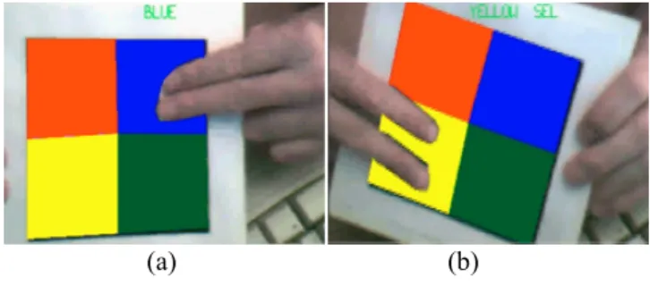
This simple gesture model describes two gestures classified by the interaction system – point and select. The point gesture is the combination of a single finger and a pointer location. A single group of fingers along with a pointer location is also classified as the gesture of pointing. The selection gesture is the combination of multiple fingers and a pointer location. An example of the recognized point and select gesture are shown in Figure 7(a) and 7(b) respectively. In this demonstration application the gesture system recognizes the colour region occupied by the finger pointer and also recognizes when selection has occurred.
(a) (b)
Figure 7 - Gesture recognition (a) Point gesture (b) Select gesture
The interaction created by this gesture model is a point and select mechanism similar to the commonly used mouse interaction with a window-based operating system. To allow a closed system of human-computer interaction, the actions generated by the hand gestures define a set of system states. The possible states of the gesture system are pointing, selecting and no hand detection. The transitions between states are triggered by a change in finger count. This transition is represented by a pair of values, (cp,cc),
indicating the previous and current finger counts. The possible values for cp and cc are 0, indicating no hand
detection, 1, indicating a single detected finger pointer, and n, indicating more than one detected finger pointer. This state machine, shown in figure 8, begins in the no hand detection state.
Figure 8 - Gesture system finite state machine
3.3 AR Hand Gesture Application
3.3.1 Virtual InterfaceThis gesture model defines a basis for simple human-computer interaction on a plane. The most common and widely used planar interaction interface is the mouse, which is found in all window-based operating systems. This type of interface took shape as a result of innovative suggestions for two-dimensional, monitor-based interaction. Over the years, window-based technology has advanced providing a rich toolset of interface widgets and their associated behaviour mechanisms. For this reason our gesture-based interaction system uses the pre-existing windows-based software technology to construct a virtual control panel system. The effect is to couple the power and visual appearance of the pre-defined windows widgets with the augmented interaction platform. This is done through an underlying, interpretive, communication link between the gesture interaction and an instantiated windows control panel dialog box. It is through this interpreter that gesture actions are converted into the operating system events that are understood by the dialog box. The widgets on the dialog box are assigned behaviour actions that are executed when the widgets are manipulated through our hand-based gesture system. In this way the user can directly manipulate a virtual representation of the dialog box. By performing gesture actions over the dialog box the appropriate behavioural feedback is presented to the user through the virtual representation.
The control panel paradigm presented here is based on a direct mapping of pattern-space coordinates to control panel dialog coordinates. This mapping is simplified by using a control panel dialog that has dimensions proportional to the 64x64 pixel target in pattern-space. A snapshot of the dialog window is taken during each render cycle and stored as an OpenGL texture. This texture is applied to a rendered polygon that is positioned over the target. By updating the snapshot every frame, the visual behaviour of the control panel dialog is presented to the user. For example, when a button goes down on the
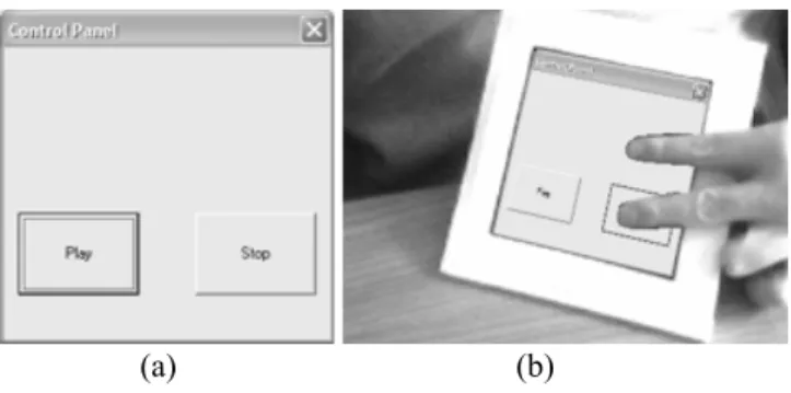
control panel dialog box, the change in button elevation is reflected in the virtual representation. Figure 9 shows an example of a simple control panel dialog box (a) that was built using standard window-based programming libraries. The virtual representation of this dialog box is shown in 9(b) where the stop button is being pressed. In other words, the two fingers are interpreted as a mouse down, which is sent to the control panel to effectively press the stop button by using hand gestures.
(a) (b)
Figure 9 – (a) Control panel dialog (b) Virtual representation augmented on the target
By using an actual dialog box in the system, the power of the standard window-based programming libraries can be exploited. These libraries simplify the process of adding system behaviour to an interface as well as reducing the complexity of the visual interface components.
3.3.2 Hand-Based Interaction
With this visual feedback mechanism in place, a mechanism for initiating interaction with the controls on the panel is described. The behaviour associated with control manipulation is defined in the normal event driven, object-oriented fashion associated with window–based application programming. Applying the gesture model to this augmented interaction requires only a simple communicative translation between the gestures, including posture parameters, and the event-based control manipulation. This translation is defined in terms of the gesture state machine outlined in figure 8. For example, when a selection gesture is recognized immediately following a pointing gesture, a mousedown event is sent to the actual control panel dialog, along with the pointer location parameter as if it were sent by the mouse hardware. This way, when the gesture occurs over a button on the virtual panel, the event generates the equivalent button press on the dialog box. On the other hand, when a pointing gesture immediately follows a selection gesture, a mouseup event is sent to the dialog along with the associated pointer location.
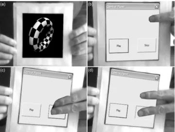
Figure 10 shows a set of images demonstrating the hand-based AR interaction system. The system begins by searching for a target in the captured scene. Once the
target is detected, augmentation begins as the target is tracked through the video sequence. In this application, the default augmentation is a video sequence of a three-dimensional, rotating torus rendered over the target (a). When the system detects target occlusion, the occlusion is assumed to be the user’s hand. For this reason, the virtual control panel (b) is augmented in place of the torus video. The control panel remains augmented for every frame where target occlusion is detected. A selection operation is demonstrated by showing multiple, separated fingers (d) after showing a single detected finger (c). During this operation, the dominant finger remained over the stop button on the control panel, which resulted in a button press (d) triggered by the mousedown event. An associated mouseup event was generated by bringing the two fingers back together in order to return the gesture system to the pointing state. The programmed behaviour associated with this control widget was to stop the augmented video playback. The system continues to track the target and it halts the augmented torus video. When the user points at the play button on the control panel and performs the selection operation and then performs a point operation, the mousedown and mouseup events trigger the behaviour of continuing the torus video playback in the AR panel.
Figure 10 – (a) Augmented torus video (b) Virtual control panel appears when occlusion is detected (c) Point gesture over the stop button (d) Select gesture
over the stop button
3.3.3 Interface Limitations
Due to the limitations of the occlusion detection system, the interface must adhere to certain restrictions. The occlusion detection is performed in pattern-space, which is a 64x64 image size. This means that regardless of the
target dimensions, the detected pointer location will be one of 4096 pixels. This location is proportionally scaled to the dimensions of the dialog box. In other words, the pointer precision is directly proportional to the dimension scaling and therefore the precision of the pointer is limited. For this reason, the widgets on the control panel need to be large enough to allow for this precision degradation. The other restriction placed on the interface design is the accuracy of the gesture recognition system. The implemented system provides the functionality to manipulate any controls that require only a point and single-click interaction, including the sophistication of the drag-and-drop operation. The success of this interaction relies directly on the success of the gesture recognition system, which in turn relies on the integrity of the occlusion detection system.
If the occlusion detection is in error this translates directly into undesired control manipulation. As an example, if a slider control is presented on the control panel, the user has the ability to select the slider knob, drag it by continuing to select while the hand is in motion, and release the knob by returning the hand to a pointing posture. While attempting to drag the knob, the effects of hand motion or lighting changes can cause the occlusion detection results to change. This could mean a change in blob count or even an undesired shift in the detected pointer location. For these reasons, complex widget manipulation is not yet practical, and is left outside the focus of this paper. The current system uses only large-scale buttons to perform monotonous system functions.
4 Results and Discussion
As with all technological applications, the value and acceptance of AR applications are directly proportional to the system performance experienced by the user. It is also true that the limiting factor in an application’s feature set, aside from developer knowledge, is the overall computational power of the computer system on which it is run.
4.1.1 Computation Time
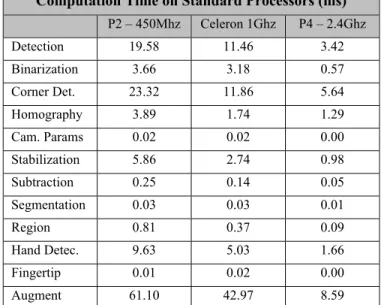
The first measure of performance is to examine the computational breakdown of the main application steps. This measure highlights areas of significant computational complexity relative to the others. Table 1 shows the amount of time (in milliseconds) taken by each of the significant phases of the AR system (Target Detection, Binarization, Corner Detection, Homography Computation, Camera Parameter Extraction, Stabilization, Subtraction, Segmentation, Connected Region Search, Hand Detection, Fingertip Location, and Augmentation). The data was gathered by timing each phase individually on three
separate computers over a period of five minutes, and listing the average time for each phase in the table. The processors used by the computers were an Intel Pentium II (450Mhz), an Intel Celeron 2 (1Ghz) and an Intel Pentium 4 (2.4Ghz). These were chosen to represent a low-end, mid-range and high-end system respectively, at the time this paper was written.
Computation Time on Standard Processors (ms)
P2 – 450Mhz Celeron 1Ghz P4 – 2.4Ghz Detection 19.58 11.46 3.42 Binarization 3.66 3.18 0.57 Corner Det. 23.32 11.86 5.64 Homography 3.89 1.74 1.29 Cam. Params 0.02 0.02 0.00 Stabilization 5.86 2.74 0.98 Subtraction 0.25 0.14 0.05 Segmentation 0.03 0.03 0.01 Region 0.81 0.37 0.09 Hand Detec. 9.63 5.03 1.66 Fingertip 0.01 0.02 0.00 Augment 61.10 42.97 8.59
Table 1 - Computation Time on Standard Processors
This table highlights the areas of significant computational complexity in the system; target detection, corner detection, stabilization and video augmentation. It also indicates the rapid decrease in overall computation time for as the processor technology advances. Since these processors are all relatively new (at most 4 years old), it can be deduced that computer vision-based AR has the potential to become mainstream technology.
4.1.2 Frame-rate performance
The second measure of performance is to examine the rate at which the system produces the final augmented images. These images are the only visual cue of the augmented environment presented to the user, and they dictate the immersion and usability of the system. This rendering frame rate indicates the feasibility of this AR interaction system as a tool using today’s computer technology. The frame-rate of the system (in hertz) was observed in each significant high-level phase (No AR Processing, Target Detection, Target Tracking, Tracking and Interaction), when run on the standard processors used in section 4.1.1. The system was left in each phase for a period of five minutes while the frame-rate was continuously recorded. The average rate during each phase
is shown in Table 2. It is important to note that these results are purposely independent of the camera capture rate in order to isolate the processing rate. This isolation was performed by allowing the image capture system to update a shared buffer, which is copied and then is used by the processing system. This means that the processing system continuously processes the latest frame captured by the system, even if it has already been processed. In practice this is clearly a waste of system resources when frames are processed faster than they are captured. However, with the image acquisition rate isolated, conclusions about the system performance can be drawn.
Frame Rate on Standard Processors (Hz)
P2 – 450Mhz Celeron 1Ghz P4 – 2.4Ghz
No Proc. 20.20 30.18 122.36
Detection 15.23 21.90 90.15
Tracking 11.57 18.29 63.59
Interaction 9.46 12.71 53.96
Table 2 – Frame rate on standard processors
The first observation that can be made based on the data shown in table 2 is the real-time performance observed by the user on the low-end and mid-range processor. Although ten frames per second is generally an unacceptable rate of image update for applications requiring high mobility, those that require little user movement can be run on lower-end systems in real-time. This suggests the possibility for simple AR applications to be accepted by the mainstream of computer users.
The second and most significant observation is the high frame-rates delivered by the high-end processor. Given that the camera hardware captures image frames at a rate of 20-30Hz, this high-end processor demonstrates the ability to perform all AR processing in the interval between image captures. In fact, this processor can approximately process each frame twice before the next frame is captured. At the time this paper was written, the fastest processor available from Intel was the Pentium 4 (3.06Ghz). With this much processing power, the image processing techniques used to deliver AR in this system become insignificant relative to the processing required to capture the images and perform routine resource management.
It is clear from these experiments that faster processors considerably improve the AR system. These results confirm the feasibility of Augmented Reality as a real-time tool for human-computer interaction in the present state of computer technology.
5 Conclusion
In this paper, a framework for interaction with the augmented environment was described. The application of image stabilization was outlined to reduce the complex problem of target occlusion in three-dimensions to the simpler problem of overlap in two-dimensions. This coordinate system is the same for the target, the target occluder, and the virtual augmentation. With this simplification, the relationship between these three key objects in the augmented environment is well defined. Using this stabilized coordinate system, the extraction of target occlusion was described to compute an accurate binary description. An overview of a hand-interaction system was described which uses the occlusion description as a basis for gesture recognition. A simple gesture model was provided to simplify the gesture classification process and to confine the actions of such gesture to those of a common computer mouse. In order to provide the functionality of a mouse to an instantiated dialog box, the communication mechanism was described which translates gesture actions into window-based events. This allows user interaction with a virtual representation of a dialog box to be performed on the actual dialog box, in order to perform system-wide behavioural changes. Experimental results were provided to demonstrate the feasibility of real-time interaction within an AR environment. Visit our website at http://www.cv.iit.nrc.ca/research/ar to see videos of this work and our other projects under development.
References
[1] Ronald T. Azuma, Yohan Baillot, Reinhold Behringer, Steven Feiner, Simon Julier, Blair MacIntyre. “Recent Advances in Augmented Reality”. IEEE Computer Graphics and Applications 21, 6 (Nov/Dec 2001), pp.34-47.
[2] Thomas P. Caudell, David W. Mizell, “Augmented Reality: An Application of Heads-Up Display Technology to Manual Manufacturing Processes” in Proceedings of Hawaii International Conference on Systems Sciences, Vol II, pp.659-669. IEEE Computer Society, January 1992.
[3] A. Censi, A. Fusiello and V. Roberto. “Image Stabilization by Features Tracking”. In "10th International Conference on Image Analysis and Processing", 1999, Venice, Italy.
[4] J. Crowley, F. Berard, and J. Coutaz. “Finger tracking as an input device for augmented reality”. In Proc. Int'l Workshop Automatic Face Gesture Recognition, pp.195-200, 1995.
[5] Michael Grafe, Raphael Wortmann, Holger Westphal. “AR-based interactive Exploration of a Museum Exhibit”, IEEE First International Augmented Reality Toolkit Workshop (ART02), Darmstadt Germany, Sept. 29, 2002.
[6] T. Heap and D. Hogg. “Towards 3D Hand Tracking Using a Deformable Model”. Proc. Int’l Conf. Automatic Face and Gesture Recognition, Killington, Vt., pp.140-145, Oct. 1996.
[7] Ramesh Jain, Rangachar Kasturi, Brian G. Schunck. “Machine Vision”. McGraw-Hill, 1995.
[8] H.Kato, M. Billinghurst, I. Poupyrev, K. Imamoto, K. Tachibana. “Virtual Object Manipulation on a Table-Top AR Environment”. In Proceedings of ISAR 2000, Oct 5th-6th, 2000
[9] Shahzad Malik, Chris McDonald, Gerhard Roth. “Hand Tracking for Interactive Pattern-based Augmented Reality”. International Symposium on Mixed and Augmented Reality (ISMAR'02), pp.117-126. September 30-October 01, 2002. Darmstadt, Germany.
[10] Shahzad Malik, Gerhard Roth, Chris McDonald. “Robust Corner Tracking for Real-time Augmented Reality”. In Proceedings of Vision Interface 2002, pp.399-406. [11] Kenji Oka, Yoichi Sato, and Hideki Koike. “Real-time
fingertip tracking and gesture recognition”, IEEE Computer Graphics and Applications, Vol. 22, No. 6, pp. 64-71, November/December 2002.
[12] Ioannis Pitas. “Digital Image Processing Algorithms”. Prentice Hall, Hemel Hempstead, Hertfordshire, 1993. [13] Bernd Schwald, Helmut Seibert, Tanja Weller. “A
Flexible Tracking Concept Applied to Medical Scenarios Using an AR Window”. International Symposium on Mixed and Augmented Reality (ISMAR'02), pp.261-262. September 30-October 01, 2002. Darmstadt, Germany. [14] G. Simon, M.-O. Berger. “Pose Estimation for Planar
Structures”. In IEEE Computer Graphics and Applications, special issue on Tracking, pp.46-53, November-December 2002.
[15] Emanuele Trucco, Alessandro Verri. “Introductory Techniques for 3D Computer Vision”. Prentice-Hall, 1998.
[16] Eike J. Umlauf, Harald Piringer, Gerhard Reitmayr, Dieter Schmalstieg. “ARLib: The Augmented Library”, IEEE First International Augmented Reality Toolkit Workshop (ART02), Darmstadt Germany, Sept. 29, 2002.
[17] Klaus Dorfmüller-Ulhaas, D. Schmalstieg. “Finger Tracking for Interaction in Augmented Environments”. Proceedings of the 2nd ACM/IEEE International Symposium on Augmented Reality (ISAR'01), pp.55-64, New York NY, Oct. 29-30, 2001.
[18] S. Veigl, A. Kaltenbach, F. Ledermann, G. Reitmayr, D. Schmalstieg. “Two-Handed Direct Interaction with ARToolKit”, IEEE First International Augmented Reality Toolkit Workshop (ART02), Darmstadt Germany, Sept. 29, 2002.
[19] Andrew Zisserman. “Geometric Framework for Vision I: Single View and Two-View Geometry”. Lecture Notes, Robotics Research Group, University of Oxford.