Publisher’s version / Version de l'éditeur:
Vous avez des questions? Nous pouvons vous aider. Pour communiquer directement avec un auteur, consultez la première page de la revue dans laquelle son article a été publié afin de trouver ses coordonnées. Si vous n’arrivez pas à les repérer, communiquez avec nous à PublicationsArchive-ArchivesPublications@nrc-cnrc.gc.ca.
Questions? Contact the NRC Publications Archive team at
PublicationsArchive-ArchivesPublications@nrc-cnrc.gc.ca. If you wish to email the authors directly, please see the first page of the publication for their contact information.
https://publications-cnrc.canada.ca/fra/droits
L’accès à ce site Web et l’utilisation de son contenu sont assujettis aux conditions présentées dans le site LISEZ CES CONDITIONS ATTENTIVEMENT AVANT D’UTILISER CE SITE WEB.
The 56th Canadian Geotechnical Conference [Proceedings], pp. 1-8, 2003-10-01
READ THESE TERMS AND CONDITIONS CAREFULLY BEFORE USING THIS WEBSITE.
https://nrc-publications.canada.ca/eng/copyright
NRC Publications Archive Record / Notice des Archives des publications du CNRC :
https://nrc-publications.canada.ca/eng/view/object/?id=95f28ae1-de40-4b49-948f-7c9d3b3cb5fa
https://publications-cnrc.canada.ca/fra/voir/objet/?id=95f28ae1-de40-4b49-948f-7c9d3b3cb5fa
NRC Publications Archive
Archives des publications du CNRC
This publication could be one of several versions: author’s original, accepted manuscript or the publisher’s version. / La version de cette publication peut être l’une des suivantes : la version prépublication de l’auteur, la version acceptée du manuscrit ou la version de l’éditeur.
Access and use of this website and the material on it are subject to the Terms and Conditions set forth at
Using the impulse response technique to estimate the length of in-situ
soil nails
Using the impulse response technique to estimate the
length of in-situ soil nails
Salloum, T.; Pernica, G.; Glazer, R.; Law, K.T.
NRCC-46735
A version of this document is published in / Une version de ce document se trouve dans :
56
thCanadian Geotechnical Conference, Winnipeg, Manitoba, Winnipeg, MB., Sept. 29-Oct. 1, 2003, pp. 1-8
USING THE IMPULSE RESPONSE TECHNIQUE TO ESTIMATE THE
LENGTH OF IN-SITU SOIL NAILS
Tareq Salloum, Carleton University, Ottawa, Ontario, Canada
Gerry Pernica, National Research Council Canada, Ottawa, Ontario, Canada
Rock Glazer, National Research Council Canada, Ottawa, Ontario, Canada
Tim Law, Carleton University, Ottawa, Ontario, Canada
ABSTRACT
Soil nails are used to prevent landslides in man-made or natural embankments. The need to install a large number of soil nails in regions of the world where site inspections are infrequent makes quality assurance difficult to achieve. The objective of this study was to develop a non-destructive field procedure using the impulse-response (IR) technique, which could quickly determine the length of installed nails. The study comprised two parts; experimental testing of laboratory and in-ground nails and the development of finite element models for the nails based on the tests. The study showed that the length of short simple nails (steel bar only) could readily be determined using the IR technique. The study also showed that the mechanical properties and condition of the cementitious cover in composite nails dominated the dynamic response and behaviour of the nails. Knowing the longitudinal wave velocity of the cementitious cover was the key parameter for obtaining a reasonable estimate of nail length.
RÉSUMÉ
On utilise des clous de sol pour empêcher un glissement de terrain dans un remblai naturel ou artificiel. On installe un grand nombre de clous de sol dans des régions du monde où les inspections de site sont rares et il est donc difficile d'obtenir une assurance de qualité. L'objectif de cette étude était de mettre au point une méthode sur le terrain non destructive permettant d'évaluer rapidement la longueur des clous installés en utilisant la technique de la réponse impulsionnelle. L'étude a comporté deux parties: des essais sur les clous en laboratoire et sur le terrain, et la modélisation par éléments finis des clous en fonction des essais. L'étude a montré que l'on pouvait facilement évaluer la longueur de clous courts et simples (barre d'acier seulement) à l'aide de la technique de réponse impulsionnelle. L'étude a également montré que les propriétés mécaniques et l'état de la couverture cimentaire des clous composites ont expliqué en grande partie la réaction dynamique et le comportement des clous. La vitesse de l'onde longitudinale de la couverture cimentaire représentait le principal paramètre pour obtenir une évaluation plausible de la longueur des clous. 1. INTRODUCTION
Soil nailing is an in-situ soil reinforcement technique for cut-slope retaining and slope stabilization systems. It has been an alternative technique to other conventional supporting systems as it offers flexibility, rapid construction and competitive costs. As a result, a tremendous number of soil nails are installed worldwide every year. Because nails can be rapidly inserted into a slope (up to 10 per hour), satisfactory quality control of the nailing technique has been difficult to achieve in some jurisdictions. A fast and reliable field technique has therefore been sought to satisfy the requirement for comprehensive quality control of soil nailing systems. This paper presents the study being conducted at the Institute for Research in Construction (IRC) of the National Research Council Canada (NRC) to adapt the impulse-response (IR) technique into a procedure for estimating the length of in-situ soil nails. The study comprised experimental tests in which, 4-m long laboratory and in-ground soil nails were constructed and tested using the IR technique. Finite element models of the laboratory and in-ground nails were developed and calibrated by comparing the numerical set of longitudinal natural frequencies to those obtained experimentally. The models were then
used to obtain the dynamic response of the nails to actual impacts so that the efficacy and suitability of the IR technique in estimating the length of soil nails from their modal frequencies could be judged.
2. EXPERIMENTAL PROGRAM 2.1 Description of Soil Nails
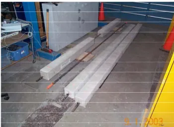
One in-ground and four laboratory soil nails were built and tested using the IR technique. The laboratory nails were assembled and housed in a large structures laboratory at NRC/IRC (Fig. 1). Three of the laboratory nails were constructed using a single steel bar surrounded by cover of normal strength concrete. The bar was 4.03 m long and 28.5 mm in diameter. The concrete cover had a 152-mm square cross-section and a 20-MPa compressive strength. The fourth nail, however, had only one constituent, the bar itself.
The remaining soil nail was installed vertically in the ground on the NRC campus in Ottawa, Ontario. The nail consisted solely of a steel bar, 25-mm in diameter and 3.44-m long, which had been carefully driven into the ground. The ground consisted of a deep layer of soft clay
topped by a thin layer of surface vegetation. Table 1 briefly notes the general configurations of the five laboratory and in-ground soil nails
Figure 1. Laboratory Soil Nails at NRC/IRC
Table 1 General Configuration of Laboratory and In-Ground Soil Nails
Nail Description A Bar exposed 160 mm at both ends3.7-m long concrete cover B Bar exposed 160 mm at both ends 0.5-m centre gap in concrete cover C Bar exposed 170 mm at one end 3.9-m long concrete cover Laboratory
D Steel bar only, 4.03 m long In-Ground S1 Steel bar only, 3.44 m long
125 mm protrudes above ground
2.2 Principles of Impulse-Response Technique
The IR technique is a non-destructive sonic method, which is generally used to determine the dynamic properties (frequencies, damping ratios and mode shapes) of structural systems. The technique consists principally of two stages; striking the system being tested with a mechanical device such as a hammer and then monitoring the response by attaching a motion transducer to the system. The impact (force) produced by the mechanical device is transient (short duration). It induces stress waves, which reflect back and forth within the structural system between boundary interfaces until the mechanically induced energy is consumed by material damping, dispersion and reflections.
2.3 Equipment
Hammers: Different sizes of instrumented hammers producing forces with various frequency contents were used to impact the laboratory and in-ground soil nails at
NRC/IRC. The hammers ranged in weight (0.3-4 kg) and each came equipped with a variety of impact heads (steel, plastic or rubber). By varying both hammer weight and impact head, the duration and amplitude of the impact force could be controlled. Each instrumented hammer was equipped with a force transducer to capture the induced force.
Transducer: To monitor the response induced by the impact, a motion transducer, for this procedure an accelerometer, was attached to the steel bar of the nail. The accelerometer was mounted with its axis of sensitivity aligned with the longitudinal axis of the nail, because only the axial response of the nail was of interest. Various types of piezo-electric accelerometers were tried in the study. The accelerometers, all of which had similar physical dimensions and dynamic response characteristics, were selected because of their broadband frequency (1 Hz to 20 kHz) and full-scale acceleration ranges (500-50000 g).
Frequency Analyser: Signals from the instrumented hammer and accelerometer were fed into a 2-channel frequency analyser with signal storage capabilities. The analyser had the ability to display the waveforms generated by the impacts and the frequency spectra (Fourier transforms and transfer functions) derived from the time signals using algorithms built into the analyser. 2.4 Experimental Procedure
Impact Delivery: Exciting the soil nail was simply accomplished by impacting the exposed end of the steel bar perpendicular to its surface as only the axial response of the nail was of interest.
Accelerometer Attachment: The bottom of each accelerometer came with a screw, which was screwed into a small steel prism. The prism, in turn, was attached with a screw to the side of the steel bar. This attachment scheme resulted from observed inadequacies in other mounting techniques, which had been evaluated in a series of earlier tests on the laboratory and in-ground nails (Pernica et al. 2002).
Figure 2 depicts both the technique used to excite the axial response of the nail and the attachment device (about 150 mm from the impacted end) connecting the accelerometer to the side of the steel bar.
Frequency Range of Analyser: The frequency range of the analyser was initially set to either 5 kHz or 10 kHz for all nails, because only the higher modes of the soil nail system, which were thought to be primarily associated with the response of the steel bar, were of interest. However, that assumption turned out to be incorrect for composite nails. Modal frequencies below 10 kHz within the induced stress wave were not restricted to the bar but travelled within the complete composite nail system (steel and concrete cover). Therefore, the frequency range finally chosen for tests on composite lab nails was 2 kHz to better capture the lower modal responses of these nails, which were now desired.
Analysing the time signals in the frequency domain focuses on identifying the dominant modal frequencies within the stress waves as the waves reflect between the two ends (head and toe) of the nail. At frequencies, which correspond to the resonances of the nail system, reflections are maximum. The resonant frequencies are thus a function of nail length (L) and the composite longitudinal wave velocity (Vc) of nail components. By determining the frequency spacing between resonant frequencies, the length of a nail can be estimated from the following relationship (Malhotra and Carino 1991):
f
V
L
c∆
=
2
[Equation 1] 12 2550 3. EXPERIMENTAL RESULTS 3.1 Laboratory Soil Nails3.1.1 Soil Nail D (Steel Bar)
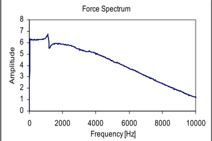
Figures 3 and 4 show the Fourier Transforms of the force and the response induced in Nail D using a small instrumented hammer with a steel head. Numerous spectral peaks, which correspond to the resonant frequencies of the steel bar, can readily be identified in the response spectrum (Fig. 4).
The constant frequency spacing between the lowest spectral peaks (about 637 Hz), coupled with the known mode shapes for these simple bar modes (Clough and Penzien 1975), indicated that the modal components within the stress wave travelled at about the same velocity. As the longitudinal wave velocity in the steel bar from actual time-of-travel measurements was about 5100 m/s, the length of the nail can be estimated at about 4.0 m from Equation 1.
3.1.2 Soil Nail A
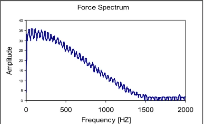
Figures 5 and 6 show the Fourier Transforms of the force and the response induced in Soil Nail A using the medium instrumented hammer with a stiff plastic head. It can be seen in Figure 6 that the first resonance occurred at about 0 Hz. It arose because Soil Nail A was not directly supported in the axial direction but simply rested on the floor slab of the structures laboratory (Davis, et al 1974).
Force Spectrum 0 1 2 3 4 5 6 7 8 0 2000 4000 6000 8000 10000 Frequency [Hz] A m plit ude
Figure 3. Fourier Transform of Hammer-Induced Force
Response Spectrum 0 20 40 60 80 100 0 140 0 2000 4000 6000 8000 10000 Frequency [Hz] A m p lit u d e 625 1275 1900 3175
Figure 4. Fourier Transform of Soil Nail D Response Also seen in Figure 6, are five successive spectral peaks (below 1.5 kHz) with frequency intervals ranging from 160–235 Hz. The breadth of these peaks indicated that a high amount of damping was present in the nail whereas their frequencies suggested that the concrete cover had mechanical properties well below those anticipated for 20-MPa concrete. As both the fundamental frequency and frequency intervals between modes were considerably less than 375 Hz, a composite wave velocity well below 3000 m/s was calculated for the 4-m nail. The apparently low wave velocity combined with large amounts of modal damping reinforced the suspicion, that visible transverse cracks in the concrete cover had substantially affected the mechanical properties of the nail. The variable frequency spacing of the peaks also implied that
the phase velocities of the modal components within the longitudinal stress wave varied with frequency.
Verification of the phase velocity phenomenon was accomplished by performing additional experimental tests using cross-correlation and cross-spectral techniques (Magrab and Blomquist 1971). Results showed that there was a drop in phase velocity as the modal frequency increased. The drop was also corroborated numerically using the finite element models by verifying the mode shapes and wavelengths that had earlier been assumed for each of the modes of vibration.
Estimating the length of a soil nail that possesses varying phase velocities was a challenging endeavour in a laboratory setting. In the field, that task would be insurmountable, as there would be no way of determining phase velocities with only one end of the nail accessible.
Force Spectrum 0 5 10 15 20 25 30 35 40 0 500 1000 1500 2000 Frequency [HZ] A m pl itude
Figure 5. Fourier Transform of Hammer-Induced Force
Response Spectrum 0 5 10 15 20 25 0 500 1000 1500 2000 Frequency [Hz] A m plit ud e 250 485 685845 1080
Figure 6. Fourier Transform of Soil Nail A Response 3.1.3 Soil Nail B
Figure 7 shows the Fourier Transform of the response induced in Soil Nail B to an impact produced by the medium instrumented hammer equipped with a stiff plastic head.
Only three major peaks below 1 kHz could be identified from the response spectrum. However, the modal frequencies are not equally spaced, as the nail did not possess a uniform cross-section but one with major material discontinuities at two locations on either side of its midpoint. The small spectral peak at 430 Hz does not appear to be a separate longitudinal mode based on the shapes and frequency spacing of the more dominant peaks. The three spectral peaks could be used to estimate the length of the nail if the wave velocity and mode shape of one or more of the modes were known. Unfortunately, this is unlikely ever to be the case since the actual cover configuration of an in-ground composite nail will always be unknown.
Response Spectrum 0 5 10 15 20 25 0 500 1000 1500 2000 Frequency [Hz] A m pl itude 205 405 545 430 1200 1480
Figure 7. Fourier Transform of Soil Nail B Response 3.1.4 Soil Nail C
Figure 8 shows the Fourier transform of the response induced in Soil Nail C to an impact produced by the medium instrumented hammer equipped with a stiff plastic head. Many spectral peaks can be seen in the response spectrum of this nail below 1.5 kHz.
Response Spectrum 0 2 4 6 8 10 12 0 500 1000 1500 2000 Frequency [Hz] A m plit ud e 230 290 450 685 910 1140 1380 1590 1890
Figure 8. Fourier Transform of Soil Nail C Response Similar to Soil Nail A, the fundamental frequency and frequency spacing of the modes were considerably less than expected (375 Hz) for a 20-MPa concrete cover. But
in contrast to Nail A, the modes were nearly equally spaced at about 230 Hz, which suggested phase velocities of about 1850 m/s. These low velocities for a composite nail were once again in keeping with the poor condition of the concrete cover, which sported many transverse cracks along the length of the nail. The cause of the peak at 290 Hz, whose presence departs from the normal modal spacing, could not be determined.
3.2 In-Ground Soil Nail S1 (Steel Bar)
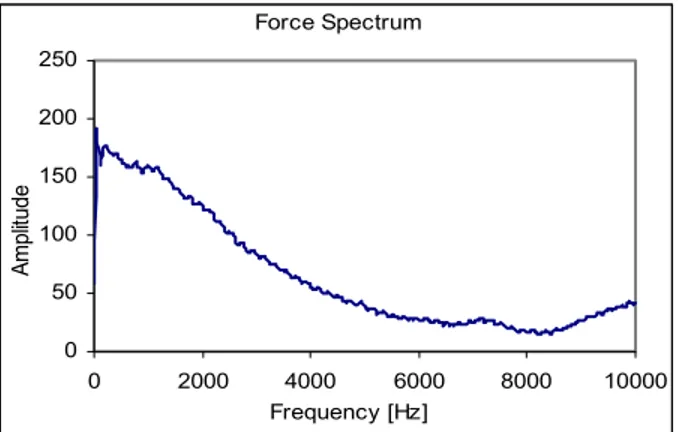
Figures 9 and 10 show the frequency spectra of the force and the response induced in Soil Nail S1 using the medium instrumented hammer equipped with a steel head. For this nail, the force produced by the hammer (Fig. 9) had sufficient energy above 5 kHz to excite many of the higher modes of the ground embedded bar.
Numerous modal peaks are well defined in the response spectrum of this simple nail. The 775-Hz fundamental frequency and frequency spacing of the modes corresponded well with the actual length (3.44 m) of the nail (steel bar), assuming a longitudinal wave velocity in the steel bar of about 5100 m/s.
Force Spectrum 0 50 100 150 200 250 0 2000 4000 6000 8000 10000 Frequency [Hz] A m pl itud e
Figure 9. Fourier Transform of Hammer-Induced Force
Response Spectrum 0 200 400 600 800 1000 1200 1400 1600 0 2000 4000 6000 8000 10000 Frequency [Hz] A m pl itude 775 1530 2250 3000 3750
Figure 10. Fourier Transform of Soil Nail S1 Response
4. FINITE ELEMENT MODELS
Dynamic analyses to obtain the dynamic properties and response of the soil-nail system were carried out using the ABAQUS finite element program. The main purpose in using ABAQUS was to create finite element models (FEMs) for the soil-nail system that could be used to determine whether the IR technique had the capabilities to accurately estimate the length of soil nails with a range of in-situ lengths and cover configurations. Several FEMs were built using ABAQUS. The models replicated the physical dimensions and layout of the laboratory and in-ground nails tested at NRC/IRC.
The models were constructed using axisymmetric elements, which provided the desired properties for bodies of revolution subjected to axially symmetric loading conditions. Nodes of the steel bar along the axis of symmetry were constrained in the lateral direction (perpendicular to the nail axis) so as to derive only the axial responses of the nails. Typical material properties were selected for steel and soil elements. The modulus of elasticity of concrete elements in composite laboratory nails was considerably reduced to levels well below that of normal concrete to reflect the cracked status of the cover. ABAQUS provides different types of contact between discrete bodies. For the composite soil nails, tied contact between adjoining steel and concrete nodes was chosen at the steel-concrete interface because no relative motion was envisioned between the two during hammer impacts. For the in-ground soil nail, “Gap” elements were used along the interface between the steel and soil to model the weak connection between the two bodies (Salloum 2003). Forces generated by hammer impacts on laboratory and in-ground soil nails were used as force inputs into their respective FEMs. An ASCII file of the time history of the hammer force was obtained from the 2-channel analyser and modified to suit the ABAQUS format for loads. 5. COMPARISON OF EXPERIMENTAL AND
NUMERICAL RESULTS 5.1 Laboratory Soil Nails 5.1.1 Soil Nail D
Figure 11 shows the response spectra obtained experimentally (dashed lines) and calculated numerically for a small hammer impact to one end of Soil Nail D. It can be seen from the figure that the two response spectra are identical with respect to resonant frequency content. However, there is one striking difference between the two spectra, their amplitudes. Resonant amplitudes obtained experimentally were considerably larger than their numerical counterparts. However, upon review, it was discovered that the large difference was caused by an error in the factor entered for the amplitude of the hammer force. The numerical response had been calculated for a
much smaller force than that used to excite the nail experimentally. Response Spectra 0 20 40 60 80 100 120 140 0 2000 4000 6000 8000 10000 Frequency [Hz] A m p lit ude Experimental
Figure 11. Comparison of Experimental and Numerical Response Spectra of Soil Nail D
5.1.2 Soil Nail A
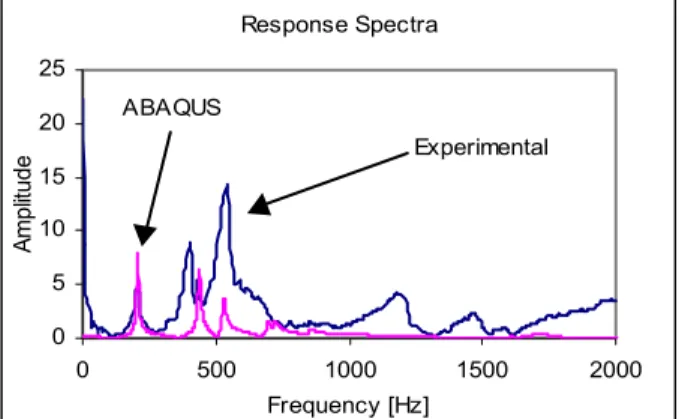
Figure 12 shows the response spectra for Soil Nail A obtained experimentally and calculated numerically. The responses were produced by the medium instrumented hammer, equipped with a stiff plastic head, striking one end of the steel bar.
Overall, the two spectra are as similar as they are different. On the positive side, it can be seen that the resonant peaks in both spectra occurred at about the same frequencies although the match between the two could be improved by a slight increase in the numerical modulus of elasticity of the concrete cover. The two spectra also support the view of a decreasing phase velocity, as the spacing between resonant peaks narrowed with increasing resonant frequency.
Response Spectra 0 5 10 15 20 25 0 500 1000 1500 2000 Frequency [Hz] A m pl itud e ABAQUS Experiment
Figure 12. Comparison of Experimental and Numerical Response Spectra of Soil Nail A
On the negative side, the peaks in the experimental spectrum are much wider than those in the numerical suggesting that the modal damping ratios for this nail are higher than those assumed in the model (2% for the first mode and 1% for the others).
Another noticeable difference in the spectra is evident around 0 Hz. The experimental spectrum contains a peak at 0 Hz, which probably resulted from the way in which the nail was supported in the laboratory. Soil Nail A was only restrained in the axial direction by the small frictional resistance provided by two short rubber strips resting on the laboratory floor slab. However, in the FEM, a soft spring was attached to one end of the steel bar. The insertion of the spring created a low-frequency resonance for the nail, which did not respond to the high-frequency impact produced by the hammer.
5.1.3 Soil Nail B
Figure 13 compares experimental and numerical response spectra obtained for Soil Nail B. The two responses were produced by the medium instrumented hammer, equipped with a stiff plastic head, striking one end of the steel bar.
Response Spectra 0 5 10 15 20 25 0 500 1000 1500 2000 Frequency [Hz] A m pl itude Experimental ABAQUS
Figure 13. Comparison of Experimental and Numerical Response Spectra of Soil Nail B
It can be seen that the first three resonant responses calculated by the FEM reasonably match those obtained experimentally. However, the experimental spectrum contains a significant second mode (around 400 Hz), which is not present in the numerical model. Perhaps the second and third (barely visible in the figure) peaks in the experimental spectrum actually represent only one mode, the second.
With respect to the amplitude of the peaks, those in the experimental spectrum are lower for the first mode and higher for the second and third than those in the numerical spectrum. A possible explanation for this difference is that the amount of modal damping present in Soil Nail B is higher for the first mode and lower for the higher modes than that selected for the FEM.
5.1.4 Soil Nail C
Figure 14 shows experimental and numerical response spectra for Soil Nail C. The two responses were produced by the medium instrumented hammer, equipped with a stiff plastic head, striking the exposed end of the steel bar. It is fairly obvious from the two spectra that resonant peaks below 1 kHz occurred at about the same frequencies. Above 1 kHz, numerical resonant frequencies and their spacing need to be increased to compare better with the experimental properties. Increasing the modulus of elasticity of the concrete cover would improve the comparison above 1 kHz but would worsen the fit below 1 kHz. The shape of the resonant peaks also indicates that the damping ratios assumed for the FEM were too low and should be approximately doubled to improve the fit.
Response Spectra 0 2 4 6 8 10 12 14 16 0 500 1000 1500 2000 Frequency [Hz] A m p lit u d e ABAQUS Experimental
Figure 14. Comparison of Experimental and Numerical Response Spectra of Soil Nail A
Response Spectra 0 500 1000 1500 2000 0 2000 4000 6000 8000 10000 Frequency [Hz] A m pl itude ABAQUS Experiment
Figure 15. Comparison of Experimental and Numerical Response Spectra of Soil Nail S1
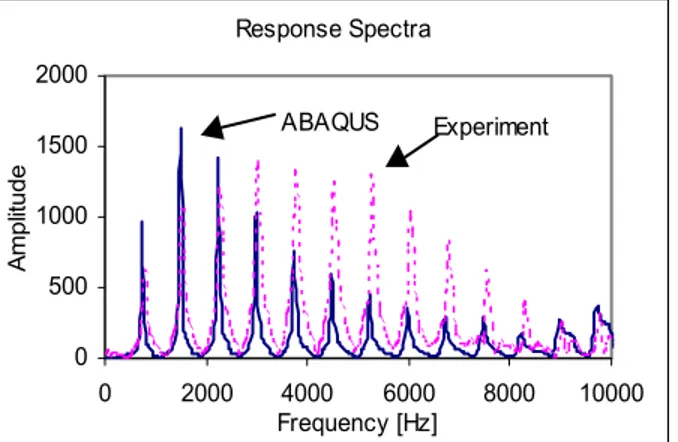
5.2 In-Ground Soil Nail S1
Figure 15 shows the numerically obtained spectrum for Soil Nail S1 superimposed on the experimental spectrum. The two responses were produced by the small instrumented hammer, equipped with a steel head, striking the above ground end of the steel bar.
The two spectra were quite similar. The only difference was in the amplitude of the resonant responses above 2 kHz. The experimental amplitudes were considerably larger than the numerical, which suggests that the amount of modal damping assumed in the FEM for the higher modes was about 2 to 4 times too high. This is just the opposite of what occurred in the laboratory nails.
6. CONCLUSIONS
a) The mechanical properties of the concrete cover in the composite laboratory nails tested at NRC/IRC effectively controlled the dynamic properties of the induced longitudinal waves. Cracks in the concrete cover of these nails significantly affected the axial dynamic properties of the nails.
b) Stress waves induced in the laboratory soil nails with cracked concrete covers may contain modal components, which possess different phase velocities. For Soil Nail A, the phase velocity of the lowest four modes decreased as the modal frequency increased. The decrease in frequency spacing of the lower modes was indicative of the variability of the phase velocity and its decrease with increasing modal frequency. In keeping with the poor condition of the concrete covers, wave velocities in the three composite laboratory nails were below 2000 m/s, considerably lower than that for normal strength concrete.
c) The medium instrumented hammer equipped with the stiff plastic head produced impacts best suited for determining the dynamic properties of the short (about 4-m long) composite laboratory nails. The impacts contained sufficient energy to excite most modes below 2 kHz. On the other hand, the small or medium instrumented hammer equipped with the steel head produced impacts best suited for determining the dynamic properties of the simple (steel bar only) laboratory and in-ground nails. The impacts contained sufficient energy to excite modes to 10 kHz.
d) The FEMs constructed for the laboratory and in-ground nails using ABAQUS produced modal properties and dynamic responses, which compared favourably with those obtained experimentally. The models were built using axisymmetric elements for nail and soil components, tied contact at steel bar-concrete interfaces and “Gap” elements at all nail-soil interfaces. Nail nodes were constrained in the lateral direction along the axis of symmetry so as to derive
only the axial properties and responses of the nail. Typical material properties were selected for steel and soil elements. The modulus of elasticity of concrete elements in the composite laboratory nails was considerably reduced to a level well below normal to reflect the cracked status of the concrete cover. Comparison of experimental and numerical response spectra also suggested that modal damping ratios for the lowest modes of the composite laboratory nails were generally well above 1% of critical.
e) A favourable estimate of nail length can be made for short composite nails using the frequencies of the lowest few modes. However, establishing a suitable wave velocity in nails with deteriorated concrete covers will be the key for obtaining an accurate estimate of nail length.
f) Obtaining the phase velocities in composite laboratory nails with deteriorated concrete covers was an extremely onerous task. The IR technique may thus be inappropriate as a stand-alone procedure for determining the length of in-ground composite nails with substantial variability in their grout covers. Using the IR technique in conjunction with a suitable FEM may lead to a better understanding of the response of composite nails and thus prove to be a useful combination for estimating the length of grouted in-ground nails.
g) A practical field approach for estimating the length of grouted in-ground nails is given below.
i) Apply the IR technique to obtain the response spectrum of a recently installed soil nail
ii) Run the finite element model with the same mechanical properties and configurations as indicated for the soil nail in the drawings and obtain a numerical response spectrum
iii) Try to match the numerical spectrum with the experimental by varying the length of the nail
iv) If a match cannot be obtained for a reasonable range of nail length, determine the pulse velocity of the grout cover using the ultrasonic pulse velocity method (ASTM C 597-97)
v) Return to Step ii) and insert revised properties. The above approach will be most applicable if the grout cover is in good condition.
7. RECOMMENDATIONS
The following recommendations pertain to the on-site execution of the IR technique:
a) Accelerometer Attachment: The accelerometer must be firmly connected to the nail so as not to slip or move when the nail is impacted. A small steel prism screwed to the side of the steel rod gave the best results.
b) Impact Delivery: The hammer should impact the steel bar perpendicular to the nail surface. Impacting the concrete cover is not recommended as repeated impacts can damage the cover and thus substantially alter the frequency content of the induced stress waves.
c) Frequency Range & Hammer Type: A frequency range of 10 kHz for the data recorder/analyser is adequate for simple “not grouted” nails. A small or medium instrumented hammer with a steel tip will be sufficient to excite desired modes to 10 kHz. For grouted laboratory nails, a frequency range of 2 kHz will suffice. A medium hammer with a stiff plastic tip will be capable of exciting desired modes to 2 kHz. d) Numerical Analysis & Finite Element Model: Using
the “Gap” element approach to model the weak connection between the simple nail and the soil gave results, which matched the experimental. However, this approach did not directly take into account the frictional forces between the steel bar and the soil. A more direct approach, say using Surface Elements, may therefore need to be investigated.
References
ABAQUS, Hibbitt, Karlsson & Sorensen, Inc., Pawtucket, Rhode Island, USA.
ASTM C597, 1997, “Standard Test Method for Pulse Velocity Through Concrete”, ASTM, Philadelphia, Pennsylvania, USA.
Carino, N.J. 2001. The Impact-Echo Method: An Overview. Proceedings of the 2001 ASCE Structures Congress & Exposition, Washington, D.C., Reston, Virginia, USA, 18 p.
Clough, R.W. and Penzien, J. 1975. Dynamic of Structures, McGraw-Hill, Inc., New York, New York, USA.
Davis, A.G. and Dunn, C.S. 1974. From Theory to Field Experience with the Non-Destructive Vibration Testing of Piles, Proc. Inst. of Civil Engrs, Vol. 57, Part 2, pp. 571-593.
Magrab, E.B. and Blomquist, D.S. 1971. The Measurement of Time-Varying Phenomena, John Wiley & Sons, Inc., New York, New York, USA, 347 p. Malhotra, V.M. and Carino, N.J. 1991. Handbook on
Nondestructive Testing of Concrete, CRC Press, Boca Raton, Florida, USA, 343 p.
Pernica, G., Law, T., Glazer, R., Lee, C.F., Tham, G. and Yue, Q. 2002. Development of a Non-Destructive Procedure to Determine the Length of In-Situ Soil Nails, 55th Annual Canadian Geotechnical Conference, Niagara Falls, Ontario, Canada
Salloum, T. 2003. Using the Impulse-Response Technique to Estimate the Length of In-Situ Soil Nails, Master Thesis Presented for the Master of Applied Science Degree, Carleton University, Ottawa, Ontario, Canada, 186 p.