Publisher’s version / Version de l'éditeur:
Vous avez des questions? Nous pouvons vous aider. Pour communiquer directement avec un auteur, consultez la première page de la revue dans laquelle son article a été publié afin de trouver ses coordonnées. Si vous n’arrivez Questions? Contact the NRC Publications Archive team at
[email protected]. If you wish to email the authors directly, please see the first page of the publication for their contact information.
https://publications-cnrc.canada.ca/fra/droits
L’accès à ce site Web et l’utilisation de son contenu sont assujettis aux conditions présentées dans le site LISEZ CES CONDITIONS ATTENTIVEMENT AVANT D’UTILISER CE SITE WEB.
Contractor Report (National Research Council of Canada. Institute for Ocean Technology); no. CR-2005-03, 2005
READ THESE TERMS AND CONDITIONS CAREFULLY BEFORE USING THIS WEBSITE. https://nrc-publications.canada.ca/eng/copyright
NRC Publications Archive Record / Notice des Archives des publications du CNRC :
https://nrc-publications.canada.ca/eng/view/object/?id=f69c8864-1274-49db-bf52-819905e8f12a https://publications-cnrc.canada.ca/fra/voir/objet/?id=f69c8864-1274-49db-bf52-819905e8f12a
NRC Publications Archive
Archives des publications du CNRC
For the publisher’s version, please access the DOI link below./ Pour consulter la version de l’éditeur, utilisez le lien DOI ci-dessous.
https://doi.org/10.4224/8894978
Access and use of this website and the material on it are subject to the Terms and Conditions set forth at
Development environment setup guide
National Research Council Canada Institute for Ocean Technology Conseil national de recherches Canada Institut des technologies oc ´eaniques
Contractor Report
CR-2005-03
Development Environment Setup Guide
P. Laurich, BA Technologies
March 2005
DOCUMENTATION PAGE REPORT NUMBER
CR-2005-03
NRC REPORT NUMBER DATE
March 2005
REPORT SECURITY CLASSIFICATION
Unclassified
DISTRIBUTION
Unlimited
TITLE
DEVELOPMENT ENVIRONMENT SETUP GUIDE
AUTHOR(S)
Peter Laurich
CORPORATE AUTHOR(S)/PERFORMING AGENCY(S)
Akamina Technologies Inc. PUBLICATION
SPONSORING AGENCY(S)
Institute for Ocean Technology, National Research Council, St. John’s, NL
IOT PROJECT NUMBER
42_2076_10
NRC FILE NUMBER
KEY WORDS
VMIVME-7700 target board, Fedora Core
PAGES 40 FIGS. 6 TABLES 5 SUMMARY
This document has been created to guide NRC staff through the process of setting up a development PC and then using the development PC to build, execute and debug loads on a target. At the time of this writing, only the VMIVME-7700 target board is supported. All of the software, documentation and scripts required for the development PC and for the target have been stored on an ftp site. The objectives of providing this ftp site together with this document are:
1. to create a single location for all of the necessary software
2. to provide the instructions to setup a consistent development environment
3. to provide the instructions to setup and use both the development PC and the target hardware. All of the software and software documentation has been stored on the Akamina Technologies ftp server. Access to this site is restricted to NRC staff. The ftp site can be accessed at ftp://www.akamina.com. The userid and password have been provided in a separate email. We have found that using the command-line ftp is more effective than attempting to use Mozilla.
ADDRESS National Research Council Institute for Ocean Technology Arctic Avenue, P. O. Box 12093 St. John's, NL A1B 3T5
National Research Council Conseil national de recherches Canada Canada Institute for Ocean Institut des technologies
Technology océaniques
DEVELOPMENT ENVIRONMENT
SETUP GUIDE
CR-2005-03
Peter Laurich Akamina Technologies Inc.
Development Environment
Setup Guide
Version: 1.0 Status: Released Oct 19, 2004 Prepared byTable of Contents
1. Introduction...3
2. Development PC Setup...4
2.1. Step One – Fedora Core 2 Installation...4
2.1.1. TFTP Server Installation and Setup...6
2.1.1.1. Download:...6
2.1.1.2. Installation:...7
2.1.2. NFS Server Installation and Setup...7
2.1.3. DHCP Server Installation and Setup...8
2.2. Step Two – Java Installation...9
2.3. Step Three – Eclipse Installation...10
2.4. Step 4 – Setup Completion...13
2.4.1. The nrcswg user...13
2.4.2. PXELINUX Boot Loader Set-up...14
3. VMIVME-7700 Target Setup...16
3.1. Documentation Download...17
3.2. VMIVME-7700 Board Configuration...17
3.3. Installation...18
3.4. Connection ...18
3.4.1. Keyboard, mouse and monitor connections...18
3.4.2. Network Connection...19
3.4.3. LED Description...19
3.5. BIOS Configuration...19
3.6. Managed Boot Agent Configuration...20
3.6.1. Obtaining the Target MAC Address...21
3.7. Console I/O...22
3.7.1. Minicom setup...22
3.7.2. Telnet login...23
4. Creating a Custom Image...24
4.1. Root Filesystem...24
4.2. Software Components...26
4.2.1. Linux Kernel...26
4.2.2. Compiling Linux BSP Package...27
4.2.3. glibc...28 4.2.4. BusyBox...28 4.2.5. Libcli...29 4.2.6. TinyLogin...30 4.2.7. GDB Server...31 4.2.8. init.d...32
4.3. Root Filesystem – Final Steps...33
4.3.1. NFS Mounted Filesystems...34
4.3.2. The First Target Boot...34
4.4. The BusyBox prompt...35
5. Adding Application Software...36
5.1. Without Eclipse...36
5.2. Using Eclipse...36
6. Remote Debugging...39
6.1. Remote Debugging using gdb...39
1. Introduction
This document has been created to guide NRC staff through the process of setting up a development PC and then using the development PC to build, execute and debug loads on a target. At the time of this writing, only the VMIVME-7700 target board is supported.
All of the software, documentation and scripts required for the development PC and for the target have been stored on an ftp site. The objectives of providing this ftp site together with this document are:
1. to create a single location for all of the necessary software
2. to provide the instructions to setup a consistent development environment
3. to provide the instructions to setup and use both the development PC and the target hardware All of the software and software documentation has been stored on the Akamina Technologies ftp server. Access to this site is restricted to NRC staff. The ftp site can be accessed at
ftp://www.akamina.com. The userid and password have been provided in a separate email. We have found that using the command-line ftp is more effective than attempting to use Mozilla.
The directory structure of the ftp site is shown below: develop |-- host |-- docs |-- fedora |-- scripts |-- tools |-- x86_tools |-- target |-- VMIVME-7700 |-- demo
The instructions in the sections that follow provide detailed information on the setup of the development PC and the setup of the target. Detailed instructions are then provided for building a custom Linux kernel and root filesystem as well as for adding application software to the target load. A final section provides instructions on how to connect a host debug session to software executing on the target.
2. Development PC Setup
The setup of the development PC includes the following steps:
1. download and installation of the Fedora Core 2 host distribution, 2. download and installation of Java,
3. download and installation of Eclipse along with C/C++ plugin and 4. completion of the setup
Eclipse is the Java-based framework on which the integrated development environment is built; Java is required for the Eclipse.
2.1. Step One – Fedora Core 2 Installation
The Fedora Core 2 images can be found on the Akamina Technologies ftp site under the directory: /develop/host/fedora/fedora2/ISO.
These images should be downloaded to any PC and burned onto CDs. Once all of the CDs have been created, your development host has been selected and it is configured to look for a boot sector on the CD, you are ready to begin the installation process. Start the installation by inserting CD 1 into the host CD drive and restarting the PC. Note that the installation configuration defined below only requires Fedora Core 2 CDs 1, 2 and 3.
Once the kernel is loaded you will be prompted to choose the terminal mode for installation. At this point just press Enter to select the graphical mode. A screen will appear asking if you would like to perform a media test – select Skip to skip the media test. You will then be prompted with the following screens:
Screen Action
Welcome to Fedora Core Click on the Next button Language Selection Click on the Next button Keyboard Configuration Click on the Next button
Upgrade Examine Choose Install Fedora Core and then Next to continue Installation Type Choose Workstation and then Next to continue
Screen Action
Automatic Partitioning Choose Remove all partitions on this system and then Next to continue. Click Yes when you are prompted with the warning information.
Boot Loader Configuration Click the Next button
Network Configuration Choose DHCP or set-up your network according to your needs. To setup your network for static IP:
1. Select manually
2. Click on Edit to enter the network information 3. uncheck Configure using DHCP
4. enter the IP address to be assigned (192.168.1.13 in this doc) 5. enter the Netmask (255.255.255.0)
6. click OK
7. enter the Hostname (dev.aka.com or whatever you wish) 8. Under Gateway:
● enter the internal IP address of your router (e.g. 192.168.1.1)
● enter the Primary and Secondary DNS information 9. click Next to continue
Firewall Configuration Check eth0 to allow all traffic from the device. Click next to continue. Additional Language Support Select any additional languages and click the Next button
Time Zone Selection Choose the appropriate time zone (Eastern Time – America/Toronto) and then click Next to continue
Set Root Password Enter the root password and then click Next to continue
Package Installation Defaults Choose Customize software packages to be installed and then Next to continue
Under Applications Check Engineering and Scientific Under Servers Check Server Configuration Tools Under Servers Check Windows File Server
Under System Check System Tools. Click Next to continue.
After clicking on the Next button you will be advised that you are about to install Linux and the applications; click Next to continue. You will then be advised that you will require Fedora Core 2 CDs 1, 2 and 3 (for the configuration specified above). Once you click Continue, all of the selected software
packages will be installed. During the installation follow the instructions to insert the other Fedora CDs. Once the installation is complete, you will be prompted to reboot your PC. Click on Reboot to continue.
Following the reboot, you will be taken through a welcome sequence where additional information is collected. The additional information includes setting up a user account. The user id should identify the developer using the system and not nrcswg. The nrcswg user account will be defined later in the set up process as the name of the project. Once all of this post-install information has been entered, the boot will complete and Fedora Core 2 is ready for use.
When you receive the login prompt, login as the developer user rather than logging in as root. You should be able to ping the IP address from other PCs on the network. You can also use Mozilla to access www.akamina.com and confirm that you have access to the network.
Once this has been done, create the following directory structure. It is important that the structure be setup as shown since some of the scripts expect the configuration to be as shown.
$(HOME) |-- host | |-- apps | |-- download | |--target |-- build |-- docs
Where $(HOME) is the base directory for your user account (typically /home/userid).
To complete the Fedora installation, the tftp, NFS and DHCP packages must be downloaded, installed and configured. The tftp server is used to transfer the Linux kernel image to the target, the NFS server must be configured to allow the target to gain access to the root filesystem, and DHCP server is needed to allow dynamic target IP configuration.
2.1.1. TFTP Server Installation and Setup
The tftp service is provided by XINETD – Internet Super Server. The following will configure both the tftp server and the tftp client.
2.1.1.1. Download:
During the development process tftp is used to retrieve the kernel from the host machine. In order to use tftp you must first install the tftp client (tftp-0.33-3.i386.rpm) and the tftp server (tftp-server-0.33-3.i386.rpm) packages. These are available on the ftp site under the directory:
/develop/host/fedora/fedora_core2/RPMS
Copy all of the packages in the RPMS directory to your host download directory (/home/userid/host/download).
Next copy the tftp file to your host download directory from the ftp site: /develop/host/scripts/tftp
2.1.1.2. Installation:
To install the software, open a terminal window, enter su to switch user to root and enter: 1. cd ~/host/download
2. rpm -i tftp-0.33-3.i386.rpm 3. rpm -i tftp-server-0.33-3.i386.rpm
You will get a NOKEY warning message with each install; the warning can be ignored. Next move the tftp file to the xinetd.d directory by entering the command:
mv tftp /etc/xinetd.d
Enter y to overwrite the existing tftp file.
2.1.2. NFS Server Installation and Setup
The Fedora installation instructions, provided above, will result in NFS being installed on your development PC. The only additional step required for NFS to be configured properly is to set up the exports, hosts.deny, and hosts.allow files. This is accomplished by downloading the exports,
hosts.deny, and hosts.allow files from the ftp site and then exporting the directories specified in the exports file.
Copy the files to your host download directory from the ftp site under the directory: /develop/host/scripts/NFS
Next, login as root, change to the host download directory and move the files to the correct directory: 1. mv exports /etc
3. mv hosts.allow /etc
In all cases, enter y to overwrite the existing files.
The hosts.allow file may require editing in order to reflect your setup. This file has following format: name of the service: IP address of machine that is allowed access to the service
The IP address field may be a comma separated list of all machines to which the access is granted. The example hosts.allow file contains only one IP address per line (192.168.1.10), and this IP address is assigned to the target board. If the IP address of 192.168.1.10 is acceptable for your configuration, there is no need to edit the file.
Export the directory using the command: /usr/sbin/exportfs -ra
In order to enable NFS server following reboot, under System Settings -> Server Settings -> Services, check NFS and then select Save. The next time the PC is rebooted, it will start the NFS server.
2.1.3. DHCP Server Installation and Setup
The target board will be dynamically configured using the DHCP protocol. In order to do this the DHCP server must be installed and configured. Fedora Core 2 comes with a pre-compiled DHCP server that is stored on the ftp site in directory:
/develop/host/fedora/fedora_core2/RPMS
Download dhcp-3.0.1rc12-4.i386.rpm package into your download directory. Next, download the configuration file dhcpd.conf from the /develop/host/scripts/dhcp directory on the ftp site. The following commands will then install the server and the configuration file:
1. cd /host/download 2. su1
3. rpm -i dhcp-3.0.1rc12-4.i386.rpm 4. rm dhcp-3.0.1rc12-4.i386.rpm 5. mv dhcpd.conf /etc
6. chown root /etc/dhcpd.conf 7. chgrp root /etc/dhcpd.conf 8. exit
You will need to edit the configuration file /etc/dhcpd.conf to reflect your setup. The section of the sample configuration file that defines the parameters to allow the target to access information from the development PC is shown below.
host nrcswg {
# Set this to the MAC address of the target hardware ethernet 00:00:00:00:00:00;
# Set the IP address to be assigned to the target board fixed-address 192.168.1.10;
option host-name "nrcswg";
# Set the IP address of the tftp server option tftp-server-name "192.168.1.14"; filename "pxelinux.0";
# Set the NFS path to point to the root filesystem on # the development PC
option root-path "192.168.1.14:/home/nrcswg/target/workingfs"; }
exit (to exit the root session)
The important aspects of the host block for the target are:
● The hardware ethernet line must be set to the MAC address of the target. This address is obtained by observing an initial boot of the target. This is explained further in section 3.6. For now, leave this number as 0.
● the fixed-address line defines the IP address to be assigned to the target
● the option tftp-server-name defines the IP address of the tftp server. This should be set to the IP address of the development PC
● the option root-path defines the path to the root filesystem on the development PC that will be NFS mounted to the target.
To enable the DHCP server following reboot, access System Settings -> Server Settings -> Services, check dhcpd and then select Save; the DHCP server will be started after the next PC rebooted.
2.2. Step Two – Java Installation
The Java development kit is needed for the Eclipse-based IDE to run. You will need to install the Java package and configure your environment. The Java package can be found on the Akamina
/develop/host/tools/java
Download Java version 1_4_2_05 to your host download directory – $(HOME)/host/download. Next, copy the script nrcswg.sh to your host download directory from the ftp site directory:
/develop/host/scripts/host_setup
Next, open a terminal window, login and enter following commands: 1. su (and login as root)
2. cd host/download
3. rpm -i j2sdk-1_4_2_05-linux-i586.rpm 4. mv nrcswg.sh /etc/profile.d
5. rm * Delete the RPM file, log out and then log back in again After you log out and log back in again, the Java package will be ready for use.
2.3. Step Three – Eclipse Installation
An Eclipse-based IDE has been chosen as the environment for building and debugging target applications. Version 3.0 of the Eclipse can be found on the ftp site under directory
develop/host/tools/Eclipse. Copy it to your host download directory, login as a user, open a terminal window, and type following commands:
cd $DOWNLOAD
unzip eclipse-SDK-3.0-linux-gtk.zip -d ../apps rm eclipse-SDK-3.0-linux-gtk.zip
Next the C/C++ plug-in for Eclipse must be downloaded and installed from the Eclipse site. This is done using the Ecliplse software itself. The software is started by executing the following commands:
cd ../apps/eclipse ./eclipse
If you get an error message indicating that java has not been installed, reboot your PC and try starting Eclipse again.
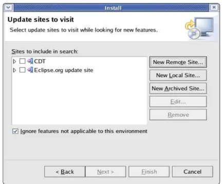
When Eclipse loads, a screen will appear. Check Use this as the default and do not ask again. Click OK to continue. Go to Help -> Software Updates -> Find and Install... from the main menu. You will be presented with following screen:
Click on the Search for new features to install and then click on Next> button. A screen will appear that allows you to specify the update sites to visit. Click on New Remote Site and the following screen will appear:
Enter CDT in the Name field, enter http://update.eclipse.org/tools/cdt/releases/new in the URL field and press the OK button. Once you press OK, the pop-up in Figure 1-2 will disappear, leaving you with the menu shown in Figure 1-3. Check the box on the left side of the CDT (Figure 1-3) and then click on the Next> button. This will cause the menu shown in Figure 1-4 to appear.
Figure 1-1. Feature Updates
Figure 1-3. New Update Site
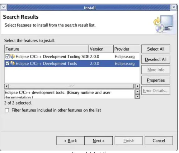
Check all available features (Figure 1-4) for CDT version 2.0.2 and click the button Next>. You will be prompted to read and accept license agreement. Click on I accept the terms in the license
agreements, click on the Next> button and then click on the Finish button. You will get a warning that
you are about to install an unsigned feature. Click on the Install button to continue with the installation. The C/C++ plug-in will then be downloaded and installed. Once the installation is complete, you will be prompted to restart the workbench. Click Yes to continue. When the Eclipse environment restarts, it is ready for use.
2.4. Step 4 – Setup Completion
To complete the setup, create the nrcswg userid and then reboot the PC.
2.4.1. The nrcswg user
A nrcswg user account is created to minimize the customization of paths used in various configuration files. All common files will be located under the nrcswg directory created for this account. The
directory structure to be created under /home/nrcswg is shown below:
/home/nrcswg |--target |-- baselinefs |-- workingfs |-- kernel |-- tftpboot |-- nfs
To create the nrcswg user, go to System Settings -> Users and Groups. Click on the Add User button, and enter following:
1. User Name: nrcswg
2. Password: type_password_here
3. Confirm Password: type_password_here
4. Uncheck the Create a private group for the user option 5. Click OK to continue
The next step is to add your the development account (not the nrcswg account) to the users group. Highlight your user account, and than click the Properties button. Choose the Groups tab and check the users group. Click OK to continue. The nrcswg account should be modified in order for you to have write access from your user account. Open a terminal window, login as root, and type:
1. cd ..
2. chmod 770 nrcswg
You should now reboot your PC before continuing.
After the PC reboots, login as the development user, open a terminal, change to the nrcswg directory (cd /home/nrcswg) and enter the following commands:
1. mkdir target 2. cd target
3. mkdir baselinefs workingfs kernel tftpboot tools tmp
2.4.2. PXELINUX Boot Loader Set-up
PXE (Preboot eXecution Environment) allows the target to boot a Linux image retrieved over a
network using information supplied by a DHCP server and then using tftp to retrieve the image. PXE is part of an Intel initiative called Wired for Management. The Wired for Management (WfM) initiative enables such features as instrumentation, use of the network as a boot device, remote wake-up, and power management.
The VMIVME-7700 target board comes with the PXE built-in. In order to enable the target to load the Linux kernel over network and to mount its root filesytem using NFS, the pxelinux boot loader must be configured. The pxelinux boot loader is part of syslinux rpm package that is installed on the
development PC as part of Fedora Core 2. To enable PXE, copy the configuration file pxelinux_conf to your download directory from the directory /develop/host/scripts/pxelinux on the ftp site. Using a terminal window enter following commands:
1. cp /usr/lib/syslinux/pxelinux.0 $TARGET/tftpboot 2. mkdir $TARGET/tftpboot/pxelinux.cfg
3. mv $DOWNLOAD/pxelinux_conf $TARGET/tftpboot/pxelinux.cfg/
The configuration file for pxelinux needs to named according to hexadecimal representation of the target IP address. The gethostip tool can be used to provide the hexadecimal representation for an IP address, for example:
gethostip 192.168.1.10 returns: C0A8010A
The following section shows the use of the output from gethostip to rename the configuration file: 1. gethostip 192.168.1.10
2. cd $TARGET/tftpboot/pxelinux.cfg 3. mv pxelinux_conf C0A8010A The development PC setup is now complete.
3. VMIVME-7700 Target Setup
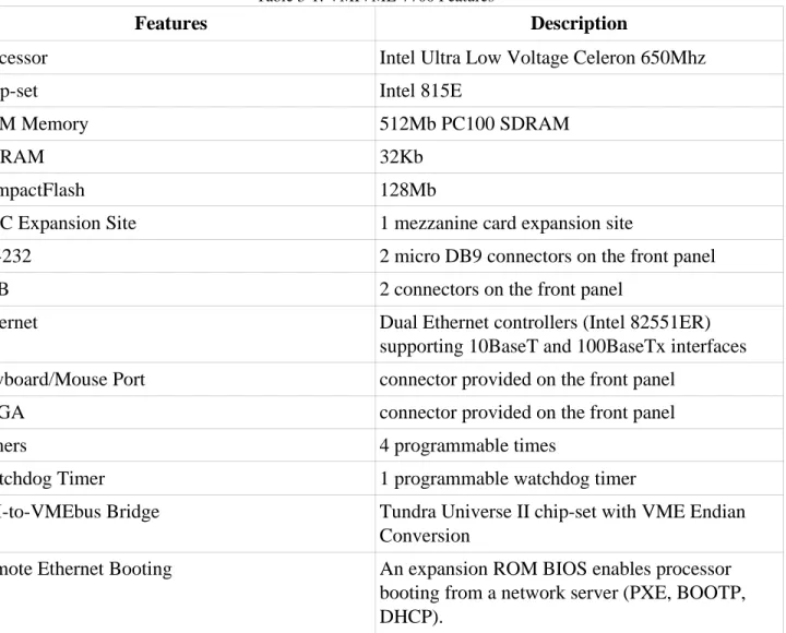
This chapter describes the installation, configuration, connection, and use of the VMIVME-7700 board from VMIC. The VMIVME-7700 board is a highly integrated single-board computer (SBC) based on the Intel Ultra Low Voltage Celeron 650 Mhz processor. Hardware components of the target board are presented in Table 3-1:
Table 3-1: VMIVME-7700 Features
Features Description
Processor Intel Ultra Low Voltage Celeron 650Mhz
Chip-set Intel 815E
RAM Memory 512Mb PC100 SDRAM
NVRAM 32Kb
CompactFlash 128Mb
PMC Expansion Site 1 mezzanine card expansion site
RS-232 2 micro DB9 connectors on the front panel
USB 2 connectors on the front panel
Ethernet Dual Ethernet controllers (Intel 82551ER) supporting 10BaseT and 100BaseTx interfaces Keyboard/Mouse Port connector provided on the front panel
SVGA connector provided on the front panel
Timers 4 programmable times
Watchdog Timer 1 programmable watchdog timer
PCI-to-VMEbus Bridge Tundra Universe II chip-set with VME Endian Conversion
Remote Ethernet Booting An expansion ROM BIOS enables processor booting from a network server (PXE, BOOTP, DHCP).
The setup of the target includes the following steps:
1. download and installation of software and documentation 2. configuration and installation of the target board
3. connection of the target to the host PC 4. target boot
3.1. Documentation Download
The documentation set provided by VMIC includes the following: 1. VMIVME-7700 Product Manual.pdf (Product manual) 2. VMIVME-7700.pdf (Overview)
The complete documentation set is available on the ftp site under the directory: /develop/target/VMIVME-7700/docs
After copying the files to the host/download directory, the following commands will move the documents to the /target/docs/VMIVME-7700 directory:
cd ~/target/docs mkdir VMIVME-7700
mv $DOWNLOAD/* VMIVME-7700
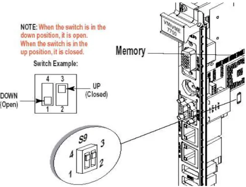
3.2. VMIVME-7700 Board Configuration
In order to enable writing to the CompactFlash device installed on board, switch (S9) number 1-4 should be changed from the UP position (default) to the DOWN position. The location of switch (S9) is shown in Figure 3-1.
The definition of switch (S9) is shown in Table 3-2.
Table 3-2: Switch (S9) Number 1-4
Select Switch Position Switch Number
CompactFlash not Write Protected Open 1 - 4 CompactFlash Write Protected Closed (default) 1 - 4
3.3. Installation
The VMIVME-7700 conforms to the VMEbus physical specification for a single slot 6U Eurocard (dual height). It can be plugged directly into any standard chassis accepting this type of board. The following steps describe the VMIC recommended method for VMIVME-7700 installation and power-up:
1. Make sure power to the equipment is off.
2. Choose a chassis slot. The documentation received with the board indicates that the VMIVME-7700 must be attached to a dual P1/P2 VMEbus backplane. However, after checking with the factory, it was confirmed that this is not mandatory; for the configuration used, the P2 connector is not required. Since the VMIVME-7700 is the only CPU board in the system, it can be placed in any slot. However, we recommend inserting the card into slot 1.
3. Connect all needed peripherals (monitor and keyboard) to the front panel. 4. Apply power to the system.
3.4. Connection
This section describes the connections required to prepare the target for power-up and boot. Figure 3-2 shows available connectors on the VMIVME-7700 board.
3.4.1. Keyboard, mouse and monitor connections
A keyboard and a mouse can be connected through M/K dual mouse/keyboard connector provided on the front panel of the board (Figure 3-2). Connection is made using the supplied “Y” Splitter Cable. A Monitor can be connected to the SVGA video connector on the front panel of the board (Figure 3-2).
3.4.2. Network Connection
A network connection is also required between the VMIVME-7700 board and the host PC. This connection can be made through a network hub or a network switch.
To connect the target to the development PC via a hub or a switch, use a standard Ethernet patch cable connected between the RJ-45 Ethernet LAN1 port on the VMIVME-7700 board (Fig. 3-2) and a free port on the hub or switch.
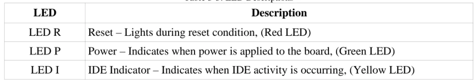
3.4.3. LED Description
Once power has been applied to the target, the board will go through a boot sequence and set board LEDs. Table 3-3 describes the indications for the VMIVME-7700 board LEDs. Refer to Figure 3-2 for the locations of the LEDs.
Table 3-3: LED Descriptions
LED Description
LED R Reset – Lights during reset condition, (Red LED)
LED P Power – Indicates when power is applied to the board, (Green LED) LED I IDE Indicator – Indicates when IDE activity is occurring, (Yellow LED)
LED Description
LED B Booting – Indicates BIOS Boot is in progress. When LED is off, CPU has finished POST ans is ready, (Red LED)
LAN1,2 Active Indicates the Ethernet is active, (Yellow LED) LAN1,2
10/100BaseTx
Indicates whether 10BaseT (Yellow LED) or 100BaseTx mode (Green LED)
3.5. BIOS Configuration
In order to access the PhoenixBIOS Setup Utility, turn on the CPU board and then wait for the Num Lock LED to light. When it does, press F2. You will hear a beep and see an error on the monitor; press F2 again to enter setup. The setup screen presents you with an intuitive interface including the
following menus: Main, Advanced, Security, Power, Boot, and Exit. You will need to modify some options in Main, Advanced, and Boot. You can navigate between different menu options using LEFT and RIGHT arrow keys. Different options provided by a menu can be navigated using the UP and DOWN arrow keys. The value of these options can be changed with +/- keys and sub-menus can be entered by pressing the Enter key.
Choose the Main menu and change following options to values indicated in square brackets: QuickBootMode: [Enabled]
LegacyDiskette A: [Disabled]
Choose the Advanced menu and change following options to values indicated in square brackets: I/O Device Configuration
Floppy disk controller: [Disabled] Installed O/S: [Other]
Large Disk Access Mode: [Other] Assign interrupt to USB [Disabled] Legacy USB support: [Disabled]
Choose the Boot menu and use the + and – keys to set the following boot sequence: MBA UNDI (Bus1 Slot6) LAN1
MBA UNDI (Bus1 Slot7) CD-ROM Drive
Hard Drive
Save your settings and exit PhoenixBIOS Setup Utility by selecting the Exit menu and the Exit Saving Changes option.
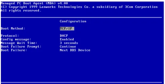
3.6. Managed Boot Agent Configuration
The managed boot agent (MBA) allows the target to be booted over a network. To configure the MBA, press Ctrl + Alt + B when you see the following message displayed on the monitor:
“ Initializing MBA. Press Ctrl+Alt+B to configure…”
If you press the hot keys while the message is displayed, you will enter the MBA-based Configuration Screen.
The Boot Method should be set to PXE. Once you have made the change, press F10 to save the configuration and exit.
3.6.1. Obtaining the Target MAC Address
The target prints out the MAC address of the network adapter when it first boots. Power on the target and then record the client MAC address. For the target used for this initial development, the following line is displayed on the terminal:
CLIENT MAC ADDR: 00 20 38 00 F5 3B
Use this information to edit the file /etc/dhcpd.conf to update the target configuration block:
host nrcswg {
# Set this to the MAC address of the target hardware ethernet 00:20:38:00:F5:3B; ...
}
Use the su command to login as root to edit this file. After the file has been edited and saved, enter the following commands to restart the DHCP server. Note that the commands assume that you are still logged in as root from the file edit step.
/sbin/service dhcpd restart exit
Your target is now ready to use.
3.7. Console I/O
The console over serial link is supported. In order to use this feature minicom terminal emulation program must be configured. Next section explains this in detail.
3.7.1. Minicom setup
The minicom program is used to provide a debug terminal for the target. Open a terminal window, login as root and type:
minicom -s
Minicom presents you with a setup menu the first time the program is run. The following steps will correctly configure the program for communication with the target:
1. Select Serial port setup
2. Set serial device to the desired serial port (for example /dev/ttyS0) 3. Set Bps/Par/Bits to 9600 8N1
4. Press F to set hardware flow control to NO 5. Press Enter
6. Select Modem and Dialing
7. Clear the Init string, Reset string, and Hang-up string 8. Press Enter
10.Select Exit
In order to use minicom from your user account some more configuration is required. The first step is to add your user account to uucp and lock groups:
1. Choose Users and Groups from System settings menu 2. Enter root password
3. Highlight your user account and select Properties 4. From the Groups tab check the uucp and lock groups 5. Exit the systems settings menu
The last step is to change permissions on the /dev/ttyS0 serial device: -| Open a terminal window, login as root
-| Type chmod 660 /dev/ttyS0 -| Close a terminal
You will need to logout from your user account and login again. Once you login, minicom is ready for use.
3.7.2. Telnet login
Beside login through serial link using minicom, it is possible to telnet into the target. For example: telnet 192.168.1.10
4. Creating a Custom Image
A custom image requires a Linux kernel and a number of other components integrated onto a root filesystem. The baseline filesystem for this projects includes the following components:
Table 4-1: Software components
Component Description
Linux kernel Linux kernel version 2.4.27 glibc GNU C library version 2.3.3 BSP package Drivers provided by VMIC
BusyBox Subset of Linux commands typically required for embedded systems libcli Library for building a Cisco-like CLI
TinyLogin Login program
gdbserver Remote debugging server scripts rcS, fstab and mtab
The following sections describe the root filesystem and all of the software components included in the baseline version of the custom image.
4.1. Root Filesystem
The basic filesystem for an embedded system includes the directories shown in the table below. The table also describes the contents of each of the top-level directories in the root filesystem.
Table 4-2: Directory structure
Directory Content
bin User command binaries dev Devices
etc System configuration files lib Essential libraries
mnt Mount point
proc Virtual filesystem for kernel
sbin Essential system administration binaries tmp Temporary files
Directory Content
usr Applications
var Variable data stored by daemons
The target directory structure includes two directories for the root filesystem – the baselinefs directory and the workingfs directory. The baselinefs directory contains the software components required in the baseline configuration. The workingfs is a copy of the baselinefs to which the user can add application software and/or experiment with customization of the software components. The image build process that is defined later in this document creates the baselinefs and then copies it to the workingfs.
The root filesystem is the set of directories and files usually found on any Unix (Linux) based system. The Filesystem Hierarchy Standard (FHS) maintained by the Filesystem Hierarchy Standard Group specifies the content of a Linux root tree. The root filesystem typically used in embedded systems differ from the root filesystem found on workstations and servers in the number of directories and files found on the filesystem.
The default root filesystem used on the target platform looks like following: / |-- bin |-- dev |-- etc |-- lib |--mnt | |-- nfs |-- proc |-- sbin |-- tmp |-- usr | |-- bin | |-- lib | |-- sbin |-- var |-- log |-- run
The directory structure must first be created by logging in as the user and entering the following commands:
2. mkdir bin dev etc lib mnt proc sbin tmp usr var 3. cd mnt
4. mkdir nfs 5. cd ../usr
6. mkdir bin lib sbin 7. cd ../var
8. mkdir log run
This empty directory structure is populated with BusyBox (binary goes into /bin, and sym-links go into /bin, /sbin, /usr/bin and /usr/sbin), libcli (goes into /usr/lib), TinyLogin (binary goes into /bin, and sym-links go into /bin, /sbin, and /usr/bin), gdbserver (binary goes into /usr/bin), and scripts (rcS goes into / etc/init.d; fstab and mtab into /etc).
4.2. Software Components
Each of the software components that make up the baseline configuration must be downloaded from the ftp site, compiled and copied to the root filesystem. The tar file downloaded from the ftp site includes all of the source code, makefiles, configuration files and some documentation. Further documentation is also available on the websites for the components.
The sections below provide details on the download and build process for the components. A fully populated baseline root filesystem is created as you execute the various steps.
4.2.1. Linux Kernel
The initial Linux kernel used for the project is the 2.4.27 Linux kernel downloaded from www.kernel.org. The kernel (linux-2.4.27.tar.bz2, and default_config files), and install script
(install_kernel.sh) are located on the ftp server. These files can be found under the following directories on the ftp site:
develop/target/VMIVME-7700/kernel develop/host/scripts/kernel
Copy all of the files on each of these directories to the host download directory. Once the downloads have been completed, open a terminal window, login as the user and execute the following commands:
1. cd $DOWNLOAD
2. chmod 777 install_kernel.sh 3. ./install_kernel.sh
This script will complete the installation of the kernel. Once all of the kernel software is in place, the kernel image can be built.
The kernel files copied in the previous step include the kernel configuration file. This file has been setup to enable the kernel options that are most likely to be required for the project.
To build a Linux kernel image that uses NFS to mount the root filesystem, open a terminal (as user), and complete the following:
1. cd $KERNEL/linux
2. make menuconfig (don't need to change the config; save and exit) 3. make dep
4. make clean 5. make bzImage 6. cd arch/i386/boot
7. cp bzImage $TARGET/tftpboot
This kernel image file will expect to find the root filesystem over the NFS.
4.2.2. Compiling Linux BSP Package
The Linux BSP package is provided by the VMIC and offers drivers for the Universe chip-set, the non-volatile RAM memory, on-board timers and the watchdog timer used on the board. The drivers are designed to work with the Linux 2.4 kernel. The package can be found on the ftp site in the / develop/target/VMIVME-7700/BSP directory. Download the vmisft-7433-3.3.tar.gz file into your download directory. In order to compile these drivers open a terminal window and enter following commands: 1. mv $DOWNLOAD/vmisft-7433-3.3.tar.gz $BUILD 2. cd $BUILD 3. gzip -d vmisft-7433-3.3.tar.gz 4. tar xvf vmisft-7433-3.3.tar 5. rm vmisft-7433-3.3.tar 6. cd vmisft-7433-3.3 7. su (enter root password) 8. cd vme_universe
9. make KERNELSRC=$KERNEL/linux KERNELREV=2.4.27 \ prefix=../../VMIVME-7700 \
DEVDIR=../../VMIVME-7700/dev/bus/vme all install 10. cd ../vminvr
11. make KERNELSRC=$KERNEL/linux KERNELREV=2.4.27 \ prefix=../../VMIVME-7700 \
DEVFILE=../../VMIVME-7700/dev/nvram all install 12. cd ../vmitmrf
13. make KERNELSRC=$KERNEL/linux KERNELREV=2.4.27 \ prefix=../../VMIVME-7700 \
DEVFILE=../../VMIVME-7700/dev/timer all install 14. cd ../vmiwdtf
15. make KERNELSRC=$KERNEL/linux KERNELREV=2.4.27 \ prefix=../../VMIVME-7700 \
DEVFILE=../../VMIVME-7700/dev/watchdog all install 16. cp -r ../../VMIVME-7700/* $BASEFS
17. exit
The drivers are now built and copied into the baselinefs directory. The drivers can be loaded manually or, eventually, the loading will be added to the system initialization code.
4.2.3. glibc
The standard C run-time library glibc has been selected for this project. The pre-built version of glibc is included with the Fedora Core 2 installation is also used on the target board. Of the many libraries that make up glibc, only the basic library file and the symbolic links for the basic library file are copied to $BASEFS/lib directory. The symbolic linker executable and the symbolic links for the dynamic linker must also be copied to $BASEFS/lib directory. To copy the files to the correct directory, open a terminal and type following commands:
1. cd /lib
2. su (enter root password when prompted)
3. cp ld-2.3.3.so ld-linux.so.2 libc-2.3.3.so libc.so.6 $BASEFS/lib
4. cp libcrypt.so.1 libcrypt-2.3.3.so libthread_db-1.0.so libthread_db.so.1 $BASEFS/lib 5. exit
The libthread_db-1.0.so library is needed only during the development cycle for remote debugging with gdbserver.
4.2.4. BusyBox
BusyBox combines tiny versions of many common UNIX utilities into a single small executable. It provides minimal replacements for most of the utilities you usually find in GNU coreutils, util-linux, etc. The utilities in BusyBox generally have fewer options than their full-featured GNU
The source code for the BusyBox is available from ftp site under the directory: develop/host/x86_tools/busybox
Download BusyBox version 1.00-rc3 into your host download directory. Next download the config file busybox_config from the ftp site directory /develop/host/scripts/busybox. Open a terminal window, and enter the following commands:
1. mv $DOWNLOAD/busybox-1.00-rc3.tar.bz2 $BUILD 2. cd $BUILD 3. bzip2 -d busybox-1.00-rc3.tar.bz2 4. tar xvf busybox-1.00-rc3.tar 5. rm busybox-1.00-rc3.tar 6. cd busybox-1.00-rc3 7. mv $DOWNLOAD/busybox_config ./.config
This version includes a terminal-based menu utility for configuring options. To configure and build BusyBox use following commands:
1. make menuconfig (no changes are required; save and exit) 2. make dep
3. make all install
This process results in the installation of BusyBox under the _install directory. The contents of this directory must be copied to the baselinefs root filesystem. The following command copies all of the files in the $BUILD/busybox-1.00-rc3/_install directory to the $BASEFS directory:
cp -r _install/* $BASEFS
The documentation for BusyBox is available in txt format, html format, and also as a man page on the ftp site under the directory:
develop/host/docs/busybox
The documentation files can be downloaded at any time.
4.2.5. Libcli
Libcli provides a telnet, command-line environment which can be embedded in other programs. This environment includes useful features such as automatic authentication, history, and command-line editing.
The source code for the libcli is available on ftp site under the directory: develop/host/x86_tools/libcli
Download version 1.8.1 into your host download directory, open a terminal window and execute the following commands: 1. mv $DOWNLOAD/libcli-1.8.1.tar.gz $BUILD 2. cd $BUILD 3. gzip -d libcli-1.8.1.tar.gz 4. tar xvf libcli-1.8.1.tar 5. rm libcli-1.8.1.tar 6. cd libcli-1.8.1 7. make
8. make PREFIX=lib_install install The final make will build the libcli libraries.
After compilation process has completed, copy all contents of $BUILD/libcli-1.8.1/lib_install/lib directory to $BASEFS/usr/lib directory. This will copy the necessary files to the baseline root filesystem. The following command will complete the copy:
cp lib_install/lib/* $BASEFS/usr/lib
The html format documentation for libcli is available on the ftp site under the directory: develop/host/docs/libcli
4.2.6. TinyLogin
TinyLogin is a collection of login utilities into a single binary. It provides the following commands: addgroup, adduser, delgroup, deluser, getty, login, passwd, su, sulogin, and vlock.
The source code for the tinylogin is available from ftp site under the directory: develop/host/x86_tools/tinylogin
Download version 1.4 into your host download directory, open a terminal window (as user) and execute the following commands:
1. mv $DOWNLOAD/tinylogin-1.4.tar.bz2 $BUILD 2. cd $BUILD 3. bzip2 -d tinylogin-1.4.tar.bz2 4. tar xvf tinylogin-1.4.tar 5. rm tinylogin-1.4.tar 6. cd tinylogin-1.4 7. make
8. su – enter root password 9. make install
10. exit
The last two make commands will build tinylogin and will install them under _install directory.
After compilation process has completed, copy all contents of $BUILD/tinylogin-1.4/_install directory to $BASEFS directory. This will copy the necessary files to the baseline root filesystem. The following command will complete the copy:
cp -r _install/* $BASEFS
The html, txt, and man pages format documentation for tinylogin is available on the ftp site under the directory:
develop/host/docs/tinylogin
A tar file will be created to make it easier to copy and install the documentation on your development PC.
4.2.7. GDB Server
The GDB server software is required to allow a development PC host debugger (gdb) to connect to the target. This software must be downloaded from the ftp site, compiled and added to the baseline root filesystem. The source code for gdbserver is available on the ftp site under the directory:
develop/host/x86_tools/gdbserver
Download version gdb-6.2.1 into your host download directory, open a terminal window (as user) and execute the following commands:
1 mv $DOWNLOAD/gdb-6.2.1.tar.bz2 $BUILD 2 cd $BUILD
3 bzip2 -d gdb-6.2.1.tar.bz2 4 tar xvf gdb-6.2.1.tar 5 rm gdb-6.2.1.tar 6 cd gdb-6.2.1/gdb/gdbserver 7 ./configure --prefix=/usr 8 make 9 strip gdbserver
These commands will build gdbserver, and strip all debug information from the executable. After compilation process has completed, copy /gdb-6.2.1/gdb/gdbserver/gdbserver file to
$BASEFS/usr/bin directory. The following command will copy the necessary file to the baseline root filesystem:
cp gdbserver $BASEFS/usr/bin
The README file for gdbserver is available on the ftp site under the directory: develop/host/docs/gdbserver
Copy the documentation to ~/target/docs.
4.2.8. init.d
System software initialization is carried out by BusyBox. The BusyBox looks for the rcS file in the / etc/init.d directory. A copy of the rcS file is stored on the ftp site under the directory /
develop/host/scripts/init.d. Download all files from the directory into your host download directory, open a terminal window (as user) and complete the following steps:
1. mkdir $BASEFS/etc/init.d 2. chmod +x $DOWNLOAD/rcS2
3. mv $DOWNLOAD/rcS $BASEFS/etc/init.d The current version of the rcS file is shown below:
#!/bin/sh
# Prepared by Akamina Technologies # 01-Oct-2004
#
# Configuration script: started by BusyBox at boot-up time #
echo
echo Execution of the /etc/init.d/rcS file started ... # Remount root filesystem r/w
echo Remounting root file system r/w ... /bin/mount -w -v -n -o remount / # Mount proc file system
echo Mounting proc file system ... /bin/mount -t proc none /proc # Configure loopback echo Starting loopback ... /sbin/ifconfig lo 127.0.0.1 up # Configure eth0 interface echo Configuring eth0 interface ... /sbin/ifconfig eth0 192.168.1.10 # Configure telnet
echo Configuring telnetd /usr/sbin/telnetd -l /bin/login
echo Execution of the /etc/init.d/rcS file ended.
The contents of the file will be extended as application software is added.
Also, the files /etc/fstab and /etc/mtab are provided. These files can be moved into the $BASEFS/etc directory using the command:
mv $DOWNLOAD/fstab $DOWNLOAD/mtab $BASEFS/etc
The file fstab contains descriptive information about the various file systems. The file mtab contains information for each mounted filesystem.
In order for serial console to work correctly file inittab is provided. It gets processed by init process which in turn starts getty process which waits for user logins. It shoud be copied under $BASEFS/etc directory:
mv $DOWNLOAD/inittab $BASEFS/etc
4.3. Root Filesystem – Final Steps
The root filesystem must include the files group, passwd and shadow to allow login. Default files have been created and must be downloaded from the ftp site. These files are available under the directory:
develop/host/scripts/passwd
Download these files to the host download directory and then move them to the /etc directory using the commands:
1. cd $DOWNLOAD
2. mv group passwd shadow $BASEFS/etc
The instructions above have resulted in the creation of the root filesystem on the baselinefs directory on the development PC. This root filesystem should be copied into the workingfs directory intended to be used for development. If, at any time, there is a need to revert back to the baseline filesystem, the working filesystem can be deleted and the baseline filesystem can be recopied into the working filesystem.
The following commands will delete the working filesystem and recreate it from the baseline filesystem:
1. cd $TARGET 2. rm -r -f workingfs 3. mkdir workingfs
4. cp -r baselinefs/* workingfs
This sequence of commands can be re-entered at any time to restart with the baseline software.
4.3.1. NFS Mounted Filesystems
An NFS mounted root filesystem is the most efficient configuration for early software development. It allows the target to access the root filesystem created on the development PC as if it where a local file system. Since the filesystem is local to the development PC, new versions of application software can be made available to the target simply by copying the files to the correct local directory. There will be a decrease in execution speed caused by network traffic but it will not be noticed during the initial phases of development and the debug-edit-download cycle is much faster with NFS. The NFS root filesystem is mounted during the Linux kernel boot process.
4.3.2. The First Target Boot
After applying power to the target board the Linux kernel is loaded into memory and the start-up scripts will complete the necessary set-up, you will be presented with a login prompt. You can use root
password as is defined on your development PC. Upon successful login it is necessary to change the root password and to create one user account. To set the root password and create a user account, enter following commands:
1. password root3
2. mkdir /home
3. adduser -h /home/admin -s /bin/ash admin4
4.4. The BusyBox prompt
With the successful completion of all of the previous steps, you will be presented with the BusyBox pound character (#) prompt.
3You will be asked to enter a password and then re-enter it for verification.
5. Adding Application Software
The following section describes the procedures for running the Hello World application on the target including:
● where to get the code
● how to compile it
● where to store the executable on the root filesystem
● how to execute the program
● how Eclipse fits in and
● using Eclipse.
5.1. Without Eclipse
The source code and makefile for the Hello World application can be found under the
develop/target/demo directory on the ftp site. Download both files into your host download directory, open a terminal window and execute the following commands:
1. mkdir $BUILD/demo
2. mv $DOWNLOAD/* $BUILD/demo 3. cd $BUILD/demo
4. make
Copy the hello.i386 executable file onto the root filesystem under the $WORKFS/usr/bin directory. With an NFS mounted root filesystem, copying the executable to the workingfs filesystem is sufficient to make it available to the target for execution. To execute the code, boot your target (if necessary), change to the /usr/bin directory on the target and type ./hello.i386.
5.2. Using Eclipse
As indicated earlier, Eclipse is the framework that provides the integrated development environment for software development. The steps below provide instructions for building the same Hello World
application as an Eclipse project.
The development code will be stored under a new directory called working. Code will be developed, compiled and then moved to the root filesystem for execution and debugging. The following steps will take you through the creation of the directory, the configuration of Eclipse and the use of Eclipse to create an executable.
From a terminal, logged in as user, execute the following commands: 1. mkdir working
3. ~/host/apps/eclipse/eclipse
At this point, Eclipse will start. The configuration of Eclipse involves the following steps: 1. Click on the Workbench icon
2. Under the File menu, select Switch Workspace ...
3. Set the workspace to the working directory that you created above. This causes Eclipse to restart with the new workspace
4. Click on the Workbench icon
5. Under the Window -> Open Perspective menu, select C/C++ 6. Select the C/C++ Projects tab
7. In the projects window, right click and then select Project...
8. Double click on C, select Standard Make C Project and then click on Next 9. Enter Demo as the Project Name and then click Finish
10. Under the Project menu uncheck Build Automatically option
At this point, the project is created but the code has yet to be added and the makefile has yet to be created. The following steps guide you through this process:
1. Right click in the projects window, select New and then select File 2. Enter makefile as the File name and then click on Finish
3. Cut and paste the code from $BUILD/demo/makefile into the makefile file that was just created. Use the Text Editor under Accessories under the main menu to open the source makefile.
4. Under the gcc line, enter the following:
cp hello.i386 $(WORKFS)/usr/bin (use the Tab key to indent)
to have the makefile copy the executable file to the correct location when it completes 5. Click on the save icon to save the file
6. Right click in the projects window, select New and then select File 7. Enter hello.c as the File name and then click on Finish
8. Cut and paste the code from $BUILD/demo/hello.c into the hello.c file that was just created. 9. Click on the save icon to save the file.
At this point, the makefile is not correctly configured to make the executable. To configure it as a makefile, complete the following steps:
1. In the projects window, right click and then select Create Make Target. 2. When the menu opens, click on Create
The executable has now been created and copied to the correct directory. Follow the steps at the end of section 5.1 to test the executable on the target.
6. Remote Debugging
6.1. Remote Debugging using gdb
Gdbserver must be started on the target board before remote debugging is possible. The gdbserver is started with the following command entered on the target:
gdbserver host_name:portNumber programNameToDebug
For host_name type anything you want. For portNumber choose for example 1234. An example command could look like:
gdbserver swg:1234 hello.i386
On the host machine start gdb by entering the following command: gdb When the gdb prompt appears type:
file /home/nrcswg/target/workingfs/usr/bin/hello.i386 (the name of the program to be debugged)
target remote 192.168.1.10:1234 (the port number you entered above) Now you can use the standard gdb commands to debug the running application.
Note: after you terminate a gdb session on the development PC, you will have to restart the gdb server on the target system before gdb can be started again.
6.2. Remote Debugging using Eclipse (version 3.0)
This section describes how to use Eclipse as the debugger. Eclipse provides a graphical front end that uses gdb as the back end. The instructions that follow assume that you have used Eclipse to create the Demo project with the Hello World application described in section 5.
To start Eclipse enter the following commands from a terminal window: 1. cd ~/host/apps/eclipse
2. ./eclipse
When Eclipse starts, it should automatically open any projects that you have created. In this case, the Demo project will be the only project defined. To ensure that the Demo project is up-to-date, right click
on the project and select Rebuild Project. Before the debugger can be used on the project, it must be configured. This is accomplished by completing the following steps:
1 From the main menu select Window -> Open Perspective and choose C/C++ 2 Start the debug feature by selecting the Run -> Debug... menu option.
3 Highlight C/C++ local and click on the New button 4 Enter the name of the item to be debugged (Demo) 5 Enter the project name (Demo)
6 Enter the name of the executable (hello.i386) 7 Select the Debugger tab
8 In the Debugger field choose GDB server 9 Change connection type to TCP
10 Enter the IP address of the target board
11 Enter the port number as assigned to the gdbserver on the target board (the example used 1234)
12 Click on the Shared Libraries tab
13 Click on Add... and locate the directory /lib.
14 Click on Apply and then click Close (we do not want to start the debugger just yet) The following table describes the steps necessary to debug hello.c
Command Description
In the terminal window for the target, enter the commands:
1. cd /usr/bin
2. gdbserver swg:1234 hello.i386
These commands start the gdb server on the target for the hello executable. The target is fairly unforgiving at this point in the development of these procedures. If something fails, you will often need to reset the target and start again. In the Eclipse window:
1. Under Run, select Debug 2. Under C/C++ select Demo (the
item to be debugged) 3. Click on Debug
This will start the debugger, connect to the target and you will see the debug window open. You can now inspect variables, single-step, ...
If the program being debugged exits or if you exit from Eclipse, the gdbserver application on the target will also exit. To start the debug session again, execute the same steps shown in the table above. If you edit the software you will need to make the new executable, make the new executable available to the target and then enter the commands in the table again. This process is fastest and easiest if you have the root filesystem NFS mounted to the target. In this configuration, the new executable is made available to the target when it is copied to the workingfs directory.