HAL Id: hal-00871235
https://hal.archives-ouvertes.fr/hal-00871235
Submitted on 9 Oct 2013
HAL is a multi-disciplinary open access
archive for the deposit and dissemination of sci-entific research documents, whether they are pub-lished or not. The documents may come from teaching and research institutions in France or abroad, or from public or private research centers.
L’archive ouverte pluridisciplinaire HAL, est destinée au dépôt et à la diffusion de documents scientifiques de niveau recherche, publiés ou non, émanant des établissements d’enseignement et de recherche français ou étrangers, des laboratoires publics ou privés.
Charge storage mechanism in nanoporous carbons and
its consequence for electrical double layer capacitors
Patrice Simon, Yury Gogotsi
To cite this version:
Patrice Simon, Yury Gogotsi. Charge storage mechanism in nanoporous carbons and its consequence for electrical double layer capacitors. Philosophical Transactions of the Royal Society A: Mathe-matical, Physical and Engineering Sciences, Royal Society, The, 2010, vol. 368, pp. 3457-3467. �10.1098/rsta.2010.0109�. �hal-00871235�
To link to this article : DOI:10.1098/rsta.2010.0109 URL : http://dx.doi.org/10.1098/rsta.2010.0109
This is an author-deposited version published in: http://oatao.univ-toulouse.fr/ Eprints ID: 8670
To cite this version:
Simon, Patrice and Gogotsi, Yury Charge storage mechanism in nanoporous
carbons and its consequence for electrical double layer capacitors. (2010) Philosophical Transactions A: Mathematical, Physical and Engineering Sciences, vol. 368 (n° 1923). pp. 3457-3467. ISSN 1364-503X
O
pen
A
rchive
T
oulouse
A
rchive
O
uverte (
OATAO
)
OATAO is an open access repository that collects the work of Toulouse researchers and makes it freely available over the web where possible.
Any correspondence concerning this service should be sent to the repository administrator: [email protected]!
doi:10.1098/rsta.2010.0109
Charge storage mechanism in nanoporous
carbons and its consequence for electrical
double layer capacitors
BY PATRICE SIMON1,* AND YURY GOGOTSI2 1Université de Toulouse, CIRIMAT, UMR-CNRS 5085,118 route de Narbonne, 31062 Toulouse Cedex, France
2Department of Materials Science and Engineering and A.J. Drexel
Nanotechnology Institute, Drexel University, Philadelphia, PA 19104, USA
Electrochemical capacitors, also known as supercapacitors, are energy storage devices that fill the gap between batteries and dielectric capacitors. Thanks to their unique features, they have a key role to play in energy storage and harvesting, acting as a complement to or even a replacement of batteries which has already been achieved in various applications. One of the challenges in the supercapacitor area is to increase their energy density. Some recent discoveries regarding ion adsorption in microporous carbon exhibiting pores in the nanometre range can help in designing the next generation of high-energy-density supercapacitors.
Keywords: energy storage; electrochemical capacitors; microporous carbons
1. Introduction
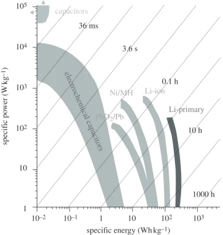
Batteries, electrochemical capacitors (ECs) and capacitors are the three main electrochemical systems that can be used to store energy (fuel cells being considered energy conversion systems). As described in the Ragone plot presented in figure 1, each of these systems offers different characteristics in terms of specific power and energy. From a general point of view, batteries, such as Li-ion batteries, can have high energy densities (up to 180 Wh kg−1
) with low power densities (up to 1 kW kg−1
). ECs, also called supercapacitors, can deliver very high power density (15 kW kg−1
) with a lower stored energy than batteries (5 Wh kg−1 ; Conway 1999). These characteristics originate from the way the energy is stored in the batteries and supercapacitors. Accordingly, supercapacitors are particularly appropriate for applications where high power is needed for a few seconds (Miller & Burke 2008; Simon & Burke 2008; Simon & Gogotsi 2008). They can also be seen as a complement to Li-ion batteries in applications where both high energy (Li-ion batteries) and high power delivery/uptake (supercapacitors) have to be achieved.
*Author for correspondence ([email protected]).
10–2 10–1 102 103 specific energy (Whkg–1) specif ic po wer (W kg –1 ) 1 1 10 102 103 104 36 ms electrochemical capacitors 3.6 s Ni/MH Li-ion PbO2/Pb Li-primary 0.1 h 10 h 1000 h capacitors 105 10
Figure 1. Ragone plot for electrochemical energy storage devices: batteries, capacitors and electrochemical capacitors (Simon & Gogotsi 2008).
2. Electrical double layer capacitors (a) Charge storage mechanism
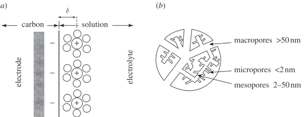
EC is a generic name used to describe various systems that can use different active materials (carbon, oxides or conducting polymers). Here, we will discuss only ECs using carbon as the active electrode material that are used today in the majority of commercialized systems (about 95%). These ECs are also called electrical double layer capacitors (EDLCs; Conway 1999). They store energy at the electrolyte–carbon interface through reversible ion adsorption onto the carbon surface, thus charging the so-called ‘double-layer capacitance’. This double-layer capacitance, firstly defined by Helmholtz (1879) and later refined by Gouy & Chapman and Stern & Geary, is schematically shown infigure 2a. This is the main differentiation from batteries, since no redox reaction is involved in the charge storage mechanism and the charge is stored only on the surface of the carbon. The capacitance can be described according to
C = 3A
d , (2.1)
where 3 is the electrolyte dielectric constant, A the surface area accessible to ions and d the distance between the centre of the ion and the carbon surface.
Double-layer capacitance for carbon materials in liquid electrolytes is in the range of 5 to 20 mF cm−2
, depending on the electrolyte. To increase the charge stored, it is necessary to increase the carbon surface area; this is achieved using
+ carbon (a) (b) solution macropores >50nm micropores <2nm mesopores 2–50nm δ electrode electrolyte + +
Figure 2. (a) Cation adsorption onto the surface of a negatively polarized electrode, charging the double-layer capacitance. (b) Pores created inside a carbon particle (about 10 mm in diameter) to develop a high surface area.
different carbon precursors as well as different synthesis techniques. Surface area is generally increased by the development of porosity in the bulk of carbon materials, leading to a porous network inside the carbon particle (figure 2b). Unfortunately, there is no simple linear relationship between the surface area and the capacitance (Barbieri et al. 2005). Indeed, more than the total porous volume, it is the way this porosity is created—i.e. the control of the pore size as well as the pore size distribution (PSD)—that has a great impact on the carbon capacitance (Simon & Gogotsi 2008). This will be discussed in §4. Activated carbon (AC) specific capacitance ranges from 100 to 200 F g−1
in aqueous medium and from 80 to 100 F g−1
in organic medium (Pandolfo & Hollenkamp 2006). The very large majority of the supercapacitors commercialized today use organic electrolytes based on fluorinated salts dissolved in carbonate- or acetonitrile (AN)-based solvents; note that the use of AN might be limited in some specific applications because of the low flash point (2◦
C). In these electrolytes, the operating voltage of a single carbon–carbon cell reaches 2.5 V.
(b) Key features
Charge storage is achieved at the surface of the carbon-active material, unlike in batteries where the charge is stored in the bulk of the material (in the chemical bonds) through electrochemical redox reactions. This surface storage first explains the low energy density (typically 5 Wh kg−1
) of the supercapacitors when compared with Li-ion cells (typically 150 Wh kg−1
). However, this storage mechanism also allows a very fast delivery of the stored charge. Thus, supercapacitor devices can deliver all the stored energy in a short time, about 5 s; this process is fully reversible and energy update can be achieved within the same time period (Simon & Gogotsi 2008).
Cyclability (or cycling stability) of supercapacitors is not limited by active material volume change between the charged and the discharged states (and associated ageing) such as in batteries. Being an electrostatic charge storage mechanism, the faradic efficiency (discharge time per charge time at the same current) is close to 100 per cent, which is higher than that of batteries. According
to supplier data sheets, supercapacitor cyclability is quasi-infinite, and Maxwell claims more than 500 000 cycles for its products with less than 20 per cent decrease of capacitance and less than 100 per cent increase of resistance (Bootscap 2009). The low temperature behaviour of supercapacitors is different from that of batteries since there is no limitation in the choice of solvent, as no carbonate is needed (Miller & Burke 2008; Simon & Gogotsi 2008). Using AN as a solvent guarantees an operation at temperatures down to −40◦
C although with degraded performances. Maximum temperature is in the same range as that of batteries, i.e. +70◦
C. This limitation is a result of electrolyte decomposition onto the high-surface-area carbon electrodes as well as of carbon oxidation.
3. Applications of electrical double layer capacitors
ECs are used when there is a high power demand, not only for power buffer and power saving units, but also for energy recovery (Kotz & Carlen 2000; Miller & Burke 2008; Simon & Burke 2008; Simon & Gogotsi 2008). Small devices (a few farads) are widely used for power buffer applications or for memory back-up in toys, cameras, video recorders, mobile phones, and so forth. Cordless tools such as screwdrivers and electric cutters using EDLCs are already available in the market (Miller & Burke 2008). A recent application that has been achieved is the emergency door opening of the Airbus A380 jumbo jet. Each of the 16 doors is powered by a 35 V/28.5 F supercapacitor module designed from series–parallel 100 F cells (Maxwell company). This application is obviously a niche market, but it is a demonstration that the EDLC technology is mature in terms of performance, reliability and safety. The Nippon Chemi-Con company has equipped several harbour cranes in Japan with a large 7 MJ supercapacitor module for energy harvesting (Miller & Simon 2008). It is constituted of 523 series–parallel connected 2.3 V/3000 F cells, combined with a standard diesel engine. During container loading operations, the supercapacitor module delivers power to assist the diesel engine. During downloading operations, the supercapacitor module is charged back. Up to 7600 forty-foot containers with mass up to 40 tonnes can be lifted up and down. The ship load can be up to 157 000 tonnes. This load can fill 35 hundred-car trains. Fuel consumption decrease of 38 per cent has been obtained using such combination and CO2 emissions have been reduced by 25 per cent (Miller & Simon 2008).
The transportation market will be a major target of EDLC manufacturers in the coming years, including hybrid electric vehicles, metro trains and tramways. Supercapacitors are already used in tramways and buses (Furubayashi et al. 2001; Bombardier 2008). In a standard tramway line, when a tram brakes, there is no way to recover the braking energy except if one tram needs to accelerate at the same time. The Mitrac system (Bombardier 2008), designed by Maxwell, enables time-shifted delivery of the braking energy for tramway re-acceleration, thus recovering the braking energy. This system has been in operation in Manheim in Germany since 2003, achieving 30 per cent energy saving.
For automotive applications, manufacturers are already proposing solutions for electrical power steering, where ECs are used for load levelling in stop-and-go traffic (Faggioli et al. 1999). The general trend is to increase the hybridization
degree of the engines in hybrid electric vehicles, to allow fast acceleration (boost) and braking energy recovery. On-board energy storage systems will be in higher demand, and a combination of batteries and EDLCs will increase the battery life cycle, explaining why EDLCs are viewed as a complement to Li-ion batteries for this market (Faggioli et al. 1999). Currently, high price limits the use of both Li-ion batteries and EDLCs in large-scale applications (e.g. load levelling). But the surprisingly high cost of materials used for EDLCs is due to a limited number of suppliers rather than the intrinsically high cost of porous carbon. Decreasing the price of carbon materials for ECs would remove the main obstacle holding them back from wider use (Chmiola & Gogotsi 2007).
4. What are the next challenges for EDLCs?
Although ECs can deliver/recover very high power peaks, today’s limitation is clearly the energy density, which is about 5 Wh kg−1
for commercial devices. This energy density limits the use of supercapacitors to a few seconds, typically within the range of 1–5 s. Increasing the energy density up to 10 Wh kg−1
would lead to an increase of the time constant and open the supercapacitor market to a wider application range where high power delivery could be achieved up to 10 s and more. With this aim, two main research axes have been developed during the past 5 years.
The first route is to design so-called hybrid systems where one supercapacitor electrode is associated with a faradic electrode in organic or aqueous electrolyte. The AC/MnO2 (Toupin et al. 2002; Fischer et al. 2007) or the AC/Ni(OOH) hybrid systems in aqueous electrolytes are being extensively investigated today. However, despite a good cyclability and an environmentally friendly electrolyte, energy density is not so greatly increased owing to the narrower voltage window (about 1.5 V). Li-based hybrid systems using organic electrolytes were firstly introduced by Amatucci’s group (Amatucci et al. 2000) with the nanostructured Li4Ti5O12/AC system, which was one of the first to reach 10 Wh kg−1
with a high power density, thanks to the use of AN as a solvent of the electrolyte. One of the most recent examples is the Li-ion capacitor from the JM Energy company that combines a pre-lithiated graphite negative intercalation electrode to a positive AC electrode (JM Energy 2009). Using this design, energy density of 15 Wh kg−1
and a power density of 10 kW kg−1
have been achieved (JM Energy 2009), which is a real advance as compared with the standard symmetric carbon systems. However, using Li intercalation-based electrodes, such energy gain is generally obtained detrimentally to the cyclability at high depth of discharge in carbonate-based electrolytes. Accordingly, important research efforts are being directed towards the increase of the stability during long-term cycling in these hybrid systems.
The second route to improve the energy density of supercapacitors is to design carbons with optimized pore structure to increase their specific capacitance. This approach allows one to retain the symmetric carbon–carbon EDLC systems that guarantees a very high power density, very high cyclability and a low temperature operation. Initial research on AC was directed towards increasing the pore volume by developing high specific surface area (SSA) and refining the activation process (§2a). However, the capacitance increase was limited even for the most porous samples. Realizing the importance of how this specific surface was created rapidly
changed the situation, and research was then directed to the understanding of the relationship between the electrolyte ion size and the carbon pore size in trying to answer the basic question: what is the optimal pore size needed in the volume of AC grains to optimize charge storage at the carbon–electrolyte interface?
The pores, which are at the origin of the increase in the developed surface area, are usually created inside carbon particles during the activation treatment. Three different pore groups are defined by IUPAC (Sing et al. 1985): micro, meso and macro pores with diameters less than 2 nm, between 2 and 50 nm, and more than 50 nm, respectively (figure 2b). These pores must be neither too big, to provide sufficient SSA (m2g−1
), nor too small to host the solvated ions from the electrolyte (average size between 1 and 2 nm in organic electrolytes; Lin et al. 2009) during the capacitor charge–discharge. The first progress in this area was to formulate carbon materials with a pore structure adapted to the size of the solvated ions in order to optimize charge storage. This is how porous ACs have been developed, with a pore size centred on small mesoporosity (3 to 5 nm), i.e. about twice the size of the solvated ions to allow ion adsorption on both pore walls. The physical or chemical activation that is used to prepare the ACs does not allow the fine control of the PSD; therefore, new routes were created to prepare materials with fine-tuned pores, such as the ‘template’ route that revealed itself as particularly efficient (Fuertes 2003; Vix-Guterl et al. 2004; Fuertes et al. 2005). Thanks to this technique, about 10–20% capacitance gains were obtained (up to 110 F g−1 in organic electrolytes).
If the above mentioned mesoporous carbons can be an alternative in terms of improving charge storage capacity, a major breakthrough was still to be found to drastically increase this capacitance. It is within this context that carbons with sub-nanometric pore size, such as carbide-derived carbons (CDCs;Chmiola et al. 2006), come into play. They are obtained from metal carbides by chlorination at temperatures ranging from 200◦
C to 1000◦
C according to the following reaction:
MC + nCl2−→MCl2n +C. (4.1)
This method allows the synthesis of carbons with a controlled pore size, since porosity originates from the leaching out of metal atoms M. By varying the temperature and duration of the process, TiC-derived carbons with porosity ranging from 0.6 to 1.2 nm were prepared. These carbons were firstly tested in an AN-based electrolyte containing 1 M NEt4BF4, for which the size of the solvated ions is 1.3 nm and 1.2 nm for (NEt+
4–7ACN) and (BF
−
4–9ACN), respectively. The change of the gravimetric capacitance (F g−1
) and the volumetric capacitance (F cm−3
) versus the CDC pore size brings out two remarkable points. First, the values of the CDCs’ gravimetric and volumetric capacitances are notably higher (140 F g−1
and 85 F cm−3
) than those of commercial ACs measured under the same conditions (approx. 100 F g−1
and approx. 45 F cm−3
), that is an increase of almost 100 per cent in the volumetric energy. Additionally, the change of CDC normalized capacitance (mF cm−2
) versus the carbon pore size was quite unexpected (figure 3;Chmiola et al. 2006). Infigure 3, the normalized capacitance was obtained by dividing the gravimetric capacitance (F g−1
) by the SSA (m2g−1 ) for each of the tested samples. Down to a pore size of 1 nm, the normalized capacitance decreases simultaneously with the decrease of the pore size, following the traditional behaviour reported in the literature (dotted line). For pore sizes
15 (a) (b) (c) (d) 10 5 normalized capacitance ( µ F cm –2) 0 CG-high CV-high CS-high CG-med CV-med CS-low CG-med new results III II TiC-CDC NPAC & SPAC
I traditional view region I d d d region II region III CV-low CS-med 1 2 3
average pore size (nm)
4 5
Figure 3. (a) Plot of specific capacitance normalized by SSA for carbons (TiC CDC (filled circles) and natural and synthetic porous activated carbons (filled squares)) in the study ofChmiola et al. (2006) and two other studies with identical electrolytes (open squares and open diamonds). Also shown are schematics of solvated ions residing in pores with distance between adjacent pore walls, (b) greater than 2 nm, (c) between 1 and 2 nm and (d) less than 1 nm.
less than 1 nm, the normalized capacitance dramatically increases, contrary to what was expected. When the size of the pores is decreased to be smaller than the size of the solvated ions, the capacitance increases in obvious contradiction to traditional beliefs, which anticipated that mesopores with a size close to twice that of the solvated ions lead to the maximum specific capacitance. This figure clearly shows the very significant contribution of the sub-nanometric pores to the charge storage mechanism. The proposed hypothesis to explain this unexpected result is the distortion of the ion solvation shell and partial desolvation of the ions, which enables the ions to access pores of a size equal to or slightly larger than the size of the bare ion (Chmiola et al. 2006). With the reduced distance (d) between the ion and the carbon surface, the capacitance increases according to equation (2.1).
Recent results obtained in organic electrolytes confirm this hypothesis of the partial desolvation of the ions when entering small pores (Aurbach et al. 2008; Chmiola et al. 2008; Lin et al. 2009). The study of the electrochemical behaviour of these CDCs in ionic liquids revealed that in these solvent-free electrolytes, the maximum capacitance was achieved when the pore size was in the range of the
carbon
(a) (b)
carbon
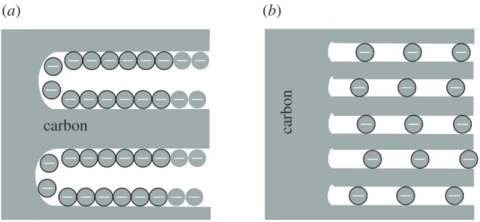
Figure 4. Electrochemical double-layer charge (a) according to the Helmholtz model and (b) in sub-nanometre pores.
ion size (Largeot et al. 2008). Accordingly, it seems that we have to reconsider the way the charge is stored in these sub-nanometre pores where no diffuse layer can be formed, moving from the traditional Helmholtz model with ions adsorbed on each side of the carbon pore walls, as presented in figure 4a, to a situation where ions can be stacked into the pores along the pore axis (figure 4b).
Recently, Meunier’s group (Huang et al.2008a,b) proposed some mathematical models to describe the ion adsorption on carbon with pore size from 0.5 up to 5 nm. They found that below 1 nm pore size, the ion adsorption could be described by an ‘electrical wire in cylinder’ model corresponding to ions aligned along the pore axis. Capacitance was calculated from the following equation:
C A =
3r30
bln(b/a0), (4.2)
where 3r is the electrolyte dielectric constant, 30 is the dielectric constant of the vacuum, b is the pore radius and a0 is the ion size in the pore. This model nicely matches with the normalized capacitance change versus pore size in zone I in figure 5 (Huang et al. 2008a,b; Simon & Gogotsi 2008). In these conditions, the NEt+
4 and BF −
4 ion diameters inside the pores (a0) were close to the bare ion sizes, confirming that at least partial desolvation was needed to access these small pores and leading to a capacitance increase according to equation (4.2).
Beyond the obtained results, the evidence of the strong contribution of the sub-nanometre (smaller than 1 nm) pores to the capacitive storage raises a number of questions for several reasons. First, it shows the limitations of fundamental understanding of ion adsorption and transport in nanoporous materials. It is very important to understand the physics of the ionic transport and the charge storage in confined pores that eliminate a diffuse layer. Also, these results have a direct consequence for applications since they demonstrate the interest in going from today’s ACs to nanostructured porous carbons and other materials. A new generation of high-energy-density supercapacitors could result from this improved understanding, thus paving the way to applications in the field of transportation in gasoline and hybrid vehicles, in particular for use with Li-ion batteries. Decorating these nanoporous carbons with nanosized oxides, for instance manganese oxide (Fischer et al. 2007), may lead to an additional pseudo-capacitance or the development of hybrid supercapacitors.
normalized capacitance (
µ
F
cm
–2)
average pore size (nm)
0 1 δ– δ– δ– δ– δ– δ– δ– δ– 2 – – + + + + b a d + + + + + + + – + + + + + + + + + + – – – – – – – – – – – 3 4 5 15 25 35 45 15 I II III IV 10 5
Figure 5. Specific capacitance normalized by SSA as a function of carbon pore size for various carbon samples. All samples were tested in the same electrolyte (NEt+
4–BF −
4 in AN at concentrations of 1.5 M (filled circles, filled squares, filled triangles), 1.0 and 1.4 M (open circles) and 1.7 M (open diamonds)). Symbols show experimental data for CDCs, templated mesoporous carbons and ACs, and curves show model fits (Huang et al.2008a,b).
Finally, these sub-nanometre porous materials can also be used as model materials to further investigate the influence of the pore size/solvated pore size ratio on the capacitance of the carbon double layers for improving our understanding of the ion transport in small pores for supercapacitors as well as other applications, such as water desalinization or medicine.
The authors thank all their students and post-docs who have contributed to this work, especially J. Chmiola (Drexel University, presently at the Lawrence Berkeley National Laboratory), C. Largeot (Université Paul Sabatier in Toulouse) and P. L. Taberna (CNRS researcher at CIRIMAT). P.S. was supported by Délégation Générale pour l’Armement in France. Y.G. was supported in part by the Fluid Interface Reactions, Structures and Transport (FIRST) Center, an Energy Frontier Research Center funded by the US Department of Energy, Office of Science, Office of Basic Energy Sciences under award no. ERKCC61. Collaboration between the participating universities was supported by a Partnership University Fund (PUF) grant.
References
Amatucci, G. G., Badway, F. & DuPasquier, A. 2000 Novel asymmetric hybrid cells and the use of pseudo-reference electrodes in three electrode cell characterization. In Intercalation compounds
for battery materials (eds G.-A. Nazri, M. Thackeray & T. Ohzuku), pp. 344–359. Pennington,
NJ: Electrochemical Society.
Aurbach, D., Levi, M. D., Salitra, G., Levy, N., Pollak, E. & Muthu, J. 2008 Cation trapping in highly porous carbon electrodes for EDLC cells. J. Electrochem. Soc. 155, A745–A753. (doi:10.1149/1.2957911)
Barbieri, O., Hahn, M., Herzog, A. & Kotz, R. 2005 Capacitance limits of high surface area activated carbons for double layer capacitors. Carbon 43, 1303–1310. (doi:10.1016/j.carbon. 2005.01.001)
Bombardier. 2008 Mitrac energy saver system. Seehttp://www.bombardier.com/files/en/supporting _docs/BT-ECO4-MITRAC_Energy_Saver.pdf.
Bootscap. 2009 Bootscap ultracapacitors. Seehttp://www.maxwell.com/ultracapacitors/datasheets /20090319_DATASHEET_PC10_1003996.9.pdf.
Chmiola, J. & Gogotsi, Y. 2007 Supercapacitors as advanced energy storage devices. Nanotechnol.
Law Bus. 4, 577–584.
Chmiola, J., Yushin, G., Gogotsi, Y., Portet, C., Simon, P. & Taberna, P.-L. 2006 Anomalous increase in carbon capacitance at pore sizes less than 1 nanometer. Science 313, 1760–1763. (doi:10.1126/science.1132195)
Chmiola, J., Largeot, C., Taberna, P. L., Simon, P. & Gogotsi, Y. 2008 Desolvation of ions in subnanometer pores and its effect on capacitance and double-layer theory. Angew. Chem. Int.
Ed. 47, 3392–3395. (doi:10.1002/anie.200704894)
Conway, B. E. 1999 Electrochemical supercapacitors: scientific fundamentals and technological
applications. Dordrecht, The Netherlands: Kluwer.
Faggioli, E., Rena, P., Danel, V., Andrieu, X., Mallant, R. & Kahlen, H. 1999 Supercapacitors for the energy management of electric vehicles. J. Power Sources 84, 261–269. (doi:10.1016/ S0378-7753(99)00326-2)
Fischer, A. E., Pettigrew, K. A., Rolison, D. R., Stroud, R. M. & Long, J. W. 2007 Incorporation of homogeneous, nanoscale MnO2 within ultraporous carbon structures via self-limiting electroless deposition: implications for electrochemical capacitors. Nano Lett. 7, 281–286. (doi:10.1021/nl062263i)
Fuertes, A. B. 2003 Template synthesis of mesoporous carbons with a controlled particle size.
J. Mater. Chem. 13, 3085–3088. (doi:10.1039/b307373d)
Fuertes, A. B., Lota, G., Centeno, T. A. & Frackowiak, E. 2005 Templated mesoporous carbons for supercapacitor application. Electrochim. Acta 50, 2799–2805. (doi:10.1016/j. electacta.2004.11.027)
Furubayashi, M., Ushio, Y., Okumura, E., Takeda, T., Andou, D. & Shibya, H. 2001 Application of high power supercapacitors to an idling stop system for city buses. Proc. 18th Int. Electric,
Fuel Cell and Hybrid Vehicle Symp., Berlin, Germany.
Helmholtz, H. V. 1879 Uber den Einfluß der elektrischen Grenzschichten bei galvanischer Spannung und der durch Wasserströmungerzeugten Potentialdiffernz. Ann. Phys. 29, 337.
Huang, J. S., Sumpter, B. G. & Meunier, V. 2008a A universal model for nanoporous carbon supercapacitors applicable to diverse pore regimes, carbon materials, and electrolytes. Chem.
Eur. J. 14, 6614–6626. (doi:10.1002/chem.200800639)
Huang, J. S., Sumpter, B. G. & Meunier, V. 2008b Theoretical model for nanoporous carbon supercapacitors. Angew. Chem. Int. Ed. 47, 520–524. (doi:10.1002/anie.200703864)
JM Energy. 2009 Introducing JM Energy lithium ion capacitor, ULTIMO. See http://www. jmenergy.co.jp/en/product.html.
Kotz, R. & Carlen, M. 2000 Principles and applications of electrochemical capacitors. Electrochim.
Acta 45, 2483–2498. (doi:10.1016/S0013-4686(00)00354-6)
Largeot, C., Portet, C., Chmiola, J., Taberna, P.-L., Gogotsi, Y. & Simon, P. 2008 Relation between the ion size and pore size for an electric double-layer capacitor. J. Am. Chem. Soc.
Lin, R., Taberna, P. L., Chmiola, J., Guay, D., Gogotsi, Y. & Simon, P. 2009 Microelectrode study of pore size, ion size, and solvent effects on the charge/discharge behavior of microporous carbons for electrical double-layer capacitors. J. Electrochem. Soc. 156, A7–A12. (doi:10.1149/ 1.3002376)
Miller, J. R. & Burke, A. F. 2008 Electrochemical capacitors: challenges and opportunities for real-world applications. Electrochem. Soc. Interface 17, 53–57.
Miller, J. R. & Simon, P. 2008 Electrochemical capacitors for energy management. Science 321, 651–652. (doi:10.1126/science.1158736)
Pandolfo, A. G. & Hollenkamp, A. F. 2006 Carbon properties and their role in supercapacitors.
J. Power Sources 157, 11–27. (doi:10.1016/j.jpowsour.2006.02.065)
Simon, P. & Burke, A. F. 2008 Nanostructured carbons: double-layer capacitance and more.
Electrochem. Soc. Interface 17, 38–43.
Simon, P. & Gogotsi, Y. 2008 Materials for electrochemical capacitors. Nat. Mater. 7, 845–854. (doi:10.1038/nmat2297)
Sing, K. S. W., Everett, D. H., Haul, R. A. V., Moscou, L., Pierotti, R. A., Rouquerol, J. & Siemieniewska, T. 1985 Reporting physisorption data for gas/solid systems with special reference to the determination of surface area and porosity. Pure Appl. Chem. 57, 603–619. (doi:10.1351/ pac198557040603)
Toupin, M., Brousse, T. & Belanger, D. 2002 Influence of microstucture on the charge storage properties of chemically synthesized manganese dioxide. Chem. Mater. 14, 3946–3952. (doi:10.1021/cm020408q)
Vix-Guterl, C., Saadallah, S., Jurewicz, K., Frackowiak, E., Reda, M., Parmentier, J., Patarin, J. & Beguin, F. 2004 Supercapacitor electrodes from new ordered porus carbon materials obtained by a templating procedure. Mater. Sci. Eng. B 108, 148–155. (doi:10.1016/j.mseb.2003.10.096)