HAL Id: tel-01961806
https://tel.archives-ouvertes.fr/tel-01961806
Submitted on 20 Dec 2018HAL is a multi-disciplinary open access
archive for the deposit and dissemination of sci-entific research documents, whether they are pub-lished or not. The documents may come from teaching and research institutions in France or abroad, or from public or private research centers.
L’archive ouverte pluridisciplinaire HAL, est destinée au dépôt et à la diffusion de documents scientifiques de niveau recherche, publiés ou non, émanant des établissements d’enseignement et de recherche français ou étrangers, des laboratoires publics ou privés.
high-intensity focussed ultrasound guided by magnetic
resonance imaging
Pierre Bour
To cite this version:
Pierre Bour. Non-invasive treatment of cardiac arrhythmias by high-intensity focussed ultrasound guided by magnetic resonance imaging. Cardiology and cardiovascular system. Université de Bor-deaux, 2017. English. �NNT : 2017BORD0731�. �tel-01961806�
THESE PRESENTEE
POUR OBTENIR LE GRADE DE
DOCTEUR DE
L’UNIVERSIT ´
E DE BORDEAUX
ECOLE DOCTORALE SCIENCES DE LA VIE ET DE LA
SANTE
SPECIALITE: BIOIMAGERIE
PAR PIERRE BOUR
Traitement non invasif des arythmies
cardiaques par ultrasons focalis´
es de haute
intensit´
e guid´
es par imagerie de r´
esonance
magn´
etique
Sous la direction de: Dr. Quesson Bruno Soutenue le 17/11/2017
Membres du jury :
Dr. KOBER Frank , Directeur de recherche CNRS, CMRBM, Marseille Rapporteur Dr. VAPPOU Jonathan, Charg´e de recherche CNRS, ICUBE, Strasbourg Rapporteur Dr. DUMONT Erik , PDG de la soci´et´e Image Guided Therapy, Pessac Examinateur Dr. QUESSON Bruno, Directeur de recherche CNRS, CRCTB, Bordeaux Examinateur
Titre: Traitement non invasif des arythmies cardiaques par ultrasons focalis´es de haute intensit´e guid´es par imagerie de r´esonance magn´etique
R´esum´e: Les ultrasons focalis´es de hautes intensit´es ont la capacit´e de d´eposer de l’´energie ultrasonore localement et de fa¸con non invasive dans les tissus biologiques. Il est possible d’exploiter les effets m´ecaniques et/ou thermiques en fonction des param`etres ultrasonores utilis´es. Guid´ee par un syst`eme d’Imagerie de R´esonance Magn´etique, cette technologie se voit dot´ee d’une modalit´e de planification et le suivi en temps r´eel de la proc´edure. Les applications actuelles des ultrasons focalis´es guid´es par IRM sont sur des organes fixes, notamment le cerveau et l’os ou le fibrome ut´erin. Dans le cas du cœur, d’une part la pr´esence de mouvements cardiaques et respiratoires constitue une difficult´e importante, tant pour le traitement ultrasonore (balistique) que pour l’IRM de temp´erature (art´efacts sur les images). D’autre part, la cage thoracique joue le rˆole de barri`ere pour la propagation des ultrasons.
Dans ce travail de th`ese, un ensemble de techniques nouvelles pour l’ablation et la stim-ulation cardiaque non invasive par ultrasons focalis´es guid´es par IRM ont ´et´e d´evelopp´ees. Une premi`ere ´etude montre la faisabilit´e technique de contrˆoler le rythme cardiaque par des impulsions ultrasonores br`eves dirig´ees vers le myocarde. L’influence des param`etres des impulsions ont ´et´e ´etudi´es quantitativement sur cœur isol´e battant puis in vivo sur un mod`ele pr´eclinique. Pour cela, un dispositif original a ´et´e d´evelopp´e. Une seconde ´
etude pr´esente des nouvelles m´ethodes rapides d’IRM permettant de cartographier simul-tan´ement la temp´erature et le d´eplacement local induit par les ultrasons focalis´es. La m´ethode est valid´ee sur le foie sur un mod`ele pr´eclinique et d´emontre qu’il est possible de corr´eler la dose thermique obtenue par thermom´etrie IRM `a un changement des propri´et´es m´ecaniques des tissus trait´es mesur´es simultan´ement.
Une troisi`eme ´etude a consist´e `a d´evelopper une technique de mesure de position de la cible en 3D temps r´eel par quelques ´el´ements de l’´emetteur ultrasonore op´erant en r´eception. Cette mesure permet de corriger dynamiquement la position du foyer ultra-sonore pour maximiser le d´epˆot d’´energie au point cibl´e, le tout monitor´e par thermom´etrie IRM temps r´eel `a une cadence de 10 images par seconde. L`a encore une validation pr´eclinique est pr´esent´ee. Ce travail de th`ese propose donc des avanc´ees importantes pour lever les verrous actuels de la technologie permettant d’envisager des traitements non in-vasifs des pathologies cardiaques par voie non invasive, le tout guid´e par IRM en temps r´eel.
Mots cl´es : coeur, ultrasons th´erapeutiques, imagerie par r´esonance magn´etique
3 Title: Non-invasive treatment of cardiac arrhythmias by high-intensity focussed ultra-sound guided by magnetic resonance imaging
Abstract: High intensity focused ultrasound has the ability to deposit ultrasonic energy locally and non-invasively into biological tissues. It is possible to exploit the mechanical and/or thermal effects according to the ultrasonic parameters used. Guided by a Magnetic Resonance Imaging (MRI) scanner, this technology is equipped with a planning modality and real-time monitoring of the procedure. As of now, applications of MRI-guided focused ultrasound are on fixed organs, including brain and bone or uterine fibroid. For the heart, the presence of cardiac and respiratory movements constitutes an important difficulty, both for the ultrasonic (ballistic) treatment and for the temperature monitoring under MRI (artefacts on images). In addition, the rib cage acts as a barrier for the propagation of ultrasounds.
In this thesis work, a set of new technological development have been developed for ablation and non-invasive cardiac stimulation using focussed MRI-guided ultrasound. A first study shows the technical feasibility of controlling heart rhythm by short ultrasound pulses targeted to the myocardium. The influence of the parameters of the pulses (dura-tion, amplitude, emission time in the cardiac cycle) were studied quantitatively on isolated beating heart then in vivo on a preclinical model. For this, an original device was de-veloped. A second study presents new rapid MRI methods for simultaneously mapping the temperature and local displacement induced by focused ultrasound. The method is validated on the liver on a preclinical model and demonstrates that it is possible to cor-relate the thermal dose obtained by MR-thermometry with a change in the mechanical properties of the treated tissues measured simultaneously.
A third study consisted in developing a technique for measuring the position of the target in 3D real-time using some elements of the ultrasonic transmitter as receivers. This measure allows to dynamically correct the position of the ultrasonic focus to maximize energy deposition at the targeted point. In addition, we monitored in real-time the pro-cedure using MR-thermometry at a rate of 10 images per second. Here again a preclinical validation is presented. This thesis work proposes important advances to remove the current locks of the technology allowing to envision non invasive treatments of cardiac pathologies, all guided by MRI in real-time.
5
Unit´e de recherche
LIRYC - L’Institut de Rythmologie et Mod´elisation Cardiaque. Centre de Recherche Cardio-Thoracique de Bordeaux - INSERM U1045
REMERCIEMENTS
A l’issue de la r´edaction de ce travail de recherche, je suis convaincu que la th`ese est loin d’ˆetre une ”course en solitaire”. En effet, je n’aurais jamais pu r´ealiser ce travail doc-toral sans le soutien d’un grand nombre de personnes dont les comp´etences, la g´en´erosit´e, la bonne humeur et l’int´erˆet manifest´es `a l’´egard de ma recherche m’ont permis de tou-jours progresser, d’apprendre et d’avancer.
En premier lieu, je tiens `a remercier mon directeur de th`ese, M. BRUNO QUESSON, et le directeur de la soci´et´e Image Guided Therapy, M. ERIK DUMONT. Je remercie M. BRUNO QUESSON pour la confiance qu’il m’a accord´ee en acceptant d’encadrer ce travail doctoral, pour ses multiples conseils et pour toutes les heures qu’il a consacr´e `a ma recherche. Il aura ´et´e d’une grande aide dans les moments de r´edaction mais ´egalement durant les exp´erimentations et ce, jusque tard le soir. Je tiens ´egalement `a le remercier pour la libert´e d’initiative qu’il m’a accord´e toute au long de ce travail doctoral. Je re-mercie M. ERIK DUMONT pour m’avoir apport´e un soutien logistique et de nombreuses r´eponses aux questions techniques que j’ai pu rencontrer tout au long de ce travail de recherche. Aussi, je remercie l’ensemble des employ´es de la soci´et´e, qui m’ont prodigu´e conseils et qui ont pu apporter des solutions concr`etes `a mes probl`emes.
Mes remerciements vont ´egalement `a FABRICE MARQUET, post-doctorant dans l’´equipe imagerie pour avoir partag´e ses connaissances dans le domaine des ultrasons et plus largement. Il m’a aid´e sur l’ensemble du travail r´ealis´e durant cette th`ese. Il a pu r´epondre `a mes interrogations et les discussions scientifiques que l’on a pu avoir durant cette th`ese m’ont beaucoup apport´e.
Je tiens ensuite `a remercier VALERY OZENNE, SOLENN TOUPIN, MATTHIEU LEPETIT-COIFFE et MARYLENE DELCEY, qui ont partag´e mon bureau durant ces 3 ann´ees. L’alternance de nos discussions scientifiques et d’autres, un peu moins, ont rythm´e ce travail et l’ont rendu tr`es convivial. Enfin, je tiens `a remercier l’ensemble de l’´equipe imagerie pour le partage de connaissances et les moments divers que nous avons partag´es.
con-seils et soutiens, tout au long de ce travail de th`ese.
Je souhaiterais exprimer ma gratitude au Pr. MICHEL HAISSAGUERRE, directeur du laboratoire et chef du service de cardiologie - ´electrophysiologie et stimulation car-diaque du CHU de Bordeaux, ainsi qu’au Pr. OLIVIER BERNUS, directeur scientifique, pour m’avoir accueilli au sein de L’Institut de RYthmologie et de mod´elisation Cardiaque.
Merci ´egalement aux rapporteurs de ce travail de th`ese, M. JONATHAN VAPPOU et M. FRANK KOBER. Les discussions et questions ont ´et´e tr`es enrichissantes.
Je remercie ma famille, mes parents et ma sœur de m’avoir soutenue durant toutes ces ann´ees et d’avoir su s’int´eresser `a mon travail. Ils ont toujours cru en moi. Je remercie ´
egalement mon parrain pour avoir assist´e `a la soutenance o`u j’ai pu concr`etement montrer le travail que j’ai effectu´e durant ces trois ann´ees. Je remercie ´egalement tous les autres membres de ma famille qui ont pens´e `a moi lors de la soutenance.
Enfin je souhaite remercier l’ensemble de mes amis ”Strasbourgeois”: Roxane, Manon, Laura, Morgane, Thomas, Arnaud, Pierre, et bien-entendu Simon. Merci `a toi d’avoir fait le d´eplacement et d’avoir ”essay´e” de me d´etendre avant la soutenance. Merci ´egalement d’avoir r´ealis´e cette petite vid´eo forte en ´emotions.
Pour finir, je souhaiterais remercier MARION, qui partage maintenant ma vie. Cette th`ese fut l’occasion de te rencontrer et de ne plus te quitter. Ton amour et ton soutien quotidien m’ont beaucoup aid´e, tu m’as donn´e le courage et la force de toujours pers´ev´erer.
3
Contents
6
7 List of Figures 9 List of Tables 13 1 Introduction 211.1 Magnetic Resonance Imaging guided HIFU . . . 21
1.2 The heart . . . 24
1.2.1 Cardiac electrophysiology . . . 25
1.2.2 Electrocardiogram . . . 26
1.2.3 Catheters . . . 27
1.2.4 Cardiac stimulation . . . 28
1.2.5 Abnormal conduction pathways . . . 29
1.3 Potential applications of HIFU on the heart . . . 31
1.3.1 Application 1: Cardiac ablation . . . 31
1.3.2 Application 2: Heart failure and cardiac pacing . . . 33
1.4 Challenges of cardiac application of HIFU therapies . . . 35
1.4.1 Motion . . . 35
1.4.2 Anatomical structures and acoustic windows . . . 36
1.4.3 Review of cardiac therapeutic ultrasound . . . 36
1.5 Context of this thesis . . . 37
1.6 References . . . 38
2 Materials and methods 45 2.1 Materials . . . 45
2.1.1 MRI system . . . 45
2.1.2 MR-data reconstruction . . . 46
2.1.3 MR-compatible HIFU system . . . 46
2.1.5 Acquisition board and ultrasound receiver . . . 51
2.1.6 Overview of the MRgHIFU platform at LIRYC . . . 52
2.2 Methods . . . 53
2.2.1 Basics of magnetic resonance imaging . . . 53
2.2.2 From MR-sequence to biomarker monitoring . . . 54
2.2.3 MR-temperature . . . 60
2.2.4 MR-ARFI . . . 62
2.2.5 Motion correction in MRI . . . 65
2.2.6 Cavitation detection . . . 69
2.3 Signal processing . . . 73
2.4 References . . . 74
3 Non-invasive cardiac pacing under MRI 81 3.1 Introduction . . . 82
3.1.1 Literature . . . 82
3.1.2 Objectives . . . 84
3.2 Materials and methods . . . 84
3.2.1 Isolated heart perfusion in Langendorff mode . . . 84
3.2.2 Physiological response monitoring . . . 87
3.2.3 Experimental protocol . . . 89
3.2.4 Feasibility of cardiac MR-ARFI monitoring . . . 90
3.3 Results . . . 92
3.3.1 Various ultrasound-induced electrical effects . . . 94
3.3.2 Feasibility of cardiac MR-ARFI monitoring . . . 96
3.3.3 In vivo proof of feasibility of HIFU stimulation . . . 97
3.3.4 Passive cavitation detection . . . 99
3.3.5 Preliminary safety assessment . . . 103
3.4 Discussion . . . 104
3.5 Conclusion . . . 107
3.6 Perspectives . . . 107
3.6.1 Acoustic windows optimization . . . 107
3.6.2 Choice of ultrasound operating frequency . . . 108
3.6.3 Sonication patterns optimization . . . 109
CONTENTS 5 4 Simultaneous monitoring of temperature and displacement under MRI113
4.1 Introduction . . . 114
4.1.1 Literature . . . 114
4.1.2 Objectives . . . 115
4.2 Materials and methods . . . 116
4.2.1 Theory on temperature and displacement monitoring . . . 116
4.2.2 MR-sequence . . . 117
4.2.3 Reconstruction & pipeline . . . 119
4.2.4 Ex vivo experiments . . . 119
4.2.5 Animal preparation . . . 119
4.2.6 Human study . . . 120
4.2.7 Optimization of the experimental parameters . . . 121
4.3 Results . . . 122
4.3.1 Calibration . . . 122
4.3.2 In vitro and in vivo . . . 124
4.3.3 Results on Volunteers . . . 128
4.4 Discussion . . . 129
4.5 Conclusion . . . 133
4.6 Perspectives . . . 134
4.7 References . . . 135
5 3D ultrasound-based motion tracking 141 5.1 Introduction . . . 141
5.1.1 Literature . . . 142
5.1.2 Objective . . . 143
5.2 Materials and Methods . . . 143
5.2.1 3D ultrasound motion correction . . . 143
5.2.2 MR acquisition and reconstruction pipeline . . . 149
5.2.3 Evaluation platform . . . 150
5.2.4 In vivo study . . . 151
5.2.5 Navigator feedback and slice following . . . 152
5.3 Results . . . 153
5.3.1 In vitro . . . 153
5.3.2 In vivo . . . 155
5.5 Conclusion . . . 160 5.6 Perspectives . . . 160 5.7 References . . . 161 6 General conclusion and perspectives 165 6.1 Patents . . . 170
7
2D Two Dimensional 3D Three Dimensional RF Radiofrequency
Heart
CRT Cardiac Resynchronization Therapy ECG Electrocardiogram
EP Electro-Physiology HF Heart Failure LA Left Atrium LV Left Ventricle
P V C Premature Ventricular Contractions RA Right Atrium
RV Right Ventricle
MR-imaging
EP I Echo Planar Imaging F OV Field Of View
GRAP P A Generalized Autocalibrating Partially Parallel Acquisitions LT D Lethal Thermal Dose
M EG Motion Encoding Gradient M R Magnetic Resonance
M RgHIF U Magnetic Resonance guided High Intensity Focused ultrasound M RI Magnetic Resonance Imaging
P RS Proton Resonance Frequency Shift
ssGE − EP I Single shot Gradient Echo Echo-Planar Imaging sequence ssSE − EP I Single shot Spin-Echo Echo-Planar Imaging sequence T D Thermal Dose
T E Echo Time T R Repetition Time
Ultrasound
ARF I Acoustic Radiation Force Impulse HIF U High Intensity Focused ultrasound M I Mechanical Index
P CD Passive Cavitation Detection U S Ultrasound
9
List of Figures
1.1 Screenshot of a focused ultrasound brain therapy . . . 23
1.2 Anatomy of the anterior surface of the heart in cross section. . . 25
1.3 Electrical conduction system of the heart. . . 25
1.4 Position of three electrodes for ECG recording. . . 26
1.5 QRS complex . . . 26
1.6 Electro-physiological catheter . . . 28
1.7 Refractory and non refractory periods . . . 29
1.8 Pacing examples . . . 29
1.9 Examples of cardiac arrhythmias . . . 30
1.10 Radiofrequency ablation . . . 31
1.11 Representative high-intensity ultrasound (HIU) and radiofrequency (RF) ablations . . . 33
1.12 Pacemaker implantation . . . 34
2.1 Transducer . . . 47
2.2 HIFU focus size . . . 48
2.3 256 elements, large animal HIFU platform . . . 48
2.4 Calibration of the 256 channel transducer . . . 49
2.5 Monitoring interface. . . 50
2.6 HIFU control tab . . . 51
2.7 Passive cavitation detection . . . 51
2.8 MRgHIFU platform at IHU-LIRYC . . . 52
2.9 Fourier transform of k-space . . . 54
2.10 Echo planar imaging sequence . . . 56
2.11 Image aliasing . . . 57
2.12 Schematic description of GRAPPA weights determination . . . 58
2.13 Pipeline of reconstruction . . . 58
2.14 MRI vendor versus the gadgetron reconstruction . . . 60
2.15 MR-Thermometry . . . 61
2.16 Displacement and shear wave generation . . . 63
2.18 Examples of rapide ARFI sequences . . . 65
2.19 Crossed-pair echo navigator . . . 67
2.20 Susceptibility artifact corrections . . . 68
2.21 MR-Thermometry in a specific slice orientation . . . 68
2.22 MR-Thermometry using an echo navigator . . . 69
2.23 Cavitation . . . 70
2.24 Cavitation detection . . . 72
3.1 Non-invasive cardiac pacing . . . 84
3.2 Langendorff setup. . . 87
3.3 64 MHz band rejecter filter. . . 88
3.4 ECG recording prototype. . . 88
3.5 Schematic of the ex vivo experimental setup and corresponding MR image. 89 3.6 Sequence user interface. . . 91
3.7 ARFI monitoring on the heart. . . 92
3.8 Example of ultrasound-induced premature ventricular contraction. . . 93
3.9 Comparison of stimulation threshold with conventional electrical pacing. . 94
3.10 Displacement monitoring during focus steering . . . 95
3.11 Monitoring of displacement during cardiac stimulation . . . 96
3.12 Monitoring of displacement along the cardiac cycle . . . 97
3.13 Displacement monitoring during electronic steering . . . 97
3.14 In vivo proof of concept of non-invasive cardiac stimulation. . . 98
3.16 Cardiac stimulation monitored by PCD . . . 101
3.17 Cavitation metrics . . . 102
3.18 Passive cavitation tresholds for sucessfull stimulation . . . 103
3.19 Examples of safety reports from the 4 in vivo cases . . . 104
3.20 Thoracic cage and registration of the heart position of a humain in red. . 108
4.1 Sequence user interface. . . 118
4.2 Description of the MR thermometry-ARFI method. . . 121
4.3 Sequence parameter optimization . . . 123
4.4 Representative results of the calibration step (ST HERM O=0) . . . 125
4.5 Results of representative ex vivo and in vivo experiments during HIFU sonication . . . 126
LIST OF FIGURES 11 4.6 Examples of temporal evolution of displacement (D), temperature (T) and
accumulated thermal dose (TD) . . . 127
4.7 Summary of results for all the sonications . . . 128
4.8 Standard deviation maps of temperature and displacement obtained on one volunteer. . . 129
4.9 Susceptibility artifact . . . 134
5.1 3D ultrasound-based motion tracking and MRI thermometry pipeline. . . 146
5.2 Displacement estimation pipeline. . . 148
5.3 Screen capture of the real-time monitoring interface . . . 149
5.4 In vitro and in vivo validation. . . 151
5.5 Schematic representation of remote computer and MRI communication. . 153
5.6 Displacement estimation validation in vitro. . . 154
5.7 Representative in vitro MR-Thermometry. . . 155
5.8 Displacement estimation in vivo on pig liver. . . 156
13
List of Tables
1.1 Publications in the field of cardiac applications of therapeutic ultrasounds . . . 37
15
R´
esum´
es en fran¸
cais
Introduction
Les ultrasons focalis´es de hautes intensit´es ont d´emontr´e leur int´erˆet dans le traitement non invasif d’organes ou de tissus pathologiques. Combin´ee `a l’imagerie par r´esonance magn´etique, cette th´erapie peut ainsi ˆetre guid´ee (ciblage) et monitor´ee grˆace `a des m´ethodes, telles que le suivi de temp´erature sous imagerie par r´esonance magn´etique ou encore le suivi du d´eplacement, induit par la force de radiation ultrasonore. Son ap-plication telle que mentionn´ee pr´ec´edemment a ´et´e r´ealis´ee avec succ`es pour le traitement du rein, du foie, de l’ut´erus et du cerveau. Deux effets de l’action des ultrasons sur les tissus peuvent ˆetre exploit´es. Le premier vient de l’absorption de la puissance ultra-sonore par les tissus qui engendre une ´el´evation de temp´erature au niveau du foyer. Si l’augmentation de temp´erature est suffisante, les tissus se n´ecrosent et meurent. Ce pro-cessus est particuli`erement int´eressant dans les cas de cancers, en permettant de d´etruire les cellules canc´ereuses de mani`ere non invasive. Un second effet est l’action m´ecanique des ultrasons sur l’organe cible. Cette action vise `a promouvoir des effets biologiques tels que la perm´eabilisation de la membrane endoth´eliale des vaisseaux sanguins ou en-core l’excitation m´ecanique des membranes cellulaires, et ceci tout en pr´eservant le tissu sous-jacent. Ces processus sont principalement domin´es par des effets de cavitations o`u de petites bulles de gaz viennent cr´eer des forces m´ecaniques oscillatoires au voisinage de la cible, au passage de l’onde ultrasonore. Dans la litt´erature, ce processus a ´et´e d´emontr´e comme permettant l’ouverture de la barri`ere h´emato-enc´ephalique, la stimula-tion de certaines r´egions du cortex moteur ou encore le d´eclenchement de contractions non spontan´ees du cœur.
Jusqu’`a pr´esent, le cœur reste un organe tr`es peu explor´e par les ultrasons focalis´es. Pourtant, plusieurs applications ont ´et´e propos´ees chez l’homme et/ou chez le petit ani-mal, qui tendent `a montrer l’int´erˆet des ultrasons dans certains traitements de maladies cardiaques. Durant cette th`ese, nous avons cibl´e deux applications : d’une part, l’ablation non invasive de r´egions pathologiques du cœur et d’autre part, la stimulation non inva-sive du cœur dans le cas de l’insuffisance cardiaque. Dans ce but, nous avons r´ealis´e une premi`ere preuve de faisabilit´e de la stimulation cardiaque sur un mod`ele gros
an-imal. Cette ´etude pr´eclinique a ´et´e suivie de deux d´eveloppements m´ethodologiques : dans un premier temps, la validation d’une m´ethode de suivi simultan´e de temp´erature et de d´eplacement sous imagerie par r´esonance magn´etique, compatible avec l’application cardiaque et dans un second temps, une m´ethode de correction 3D et temps r´eel du foyer ultrasonore.
Etude # 1
`
A l’heure actuelle, il n’existe pas de dispositif de stimulation cardiaque non invasif acceptable pour une utilisation prolong´ee chez des patients conscients. Depuis 2004, les ultrasons focalis´es de hautes intensit´es ont ´et´e propos´es et ´etudi´es pour r´ealiser des stim-ulations `a distance en utilisant la r´eversibilit´e du couplage ´electrom´ecanique des cellules cardiaques. Dans cette ´etude, nous avons design´e un dispositif de stimulation cardiaque extracorporelle et test´e son efficacit´e et sa s´ecurit´e. Nous avons men´e des exp´eriences ex vivo et in vivo sur un mod`ele gros animal (cochon) pour ´evaluer les perspectives clin-iques d’une telle technique, en se rapprochant le plus possible des contraintes anatomclin-iques retrouv´ees chez l’homme. Le seuil de stimulation cardiaque a ´et´e d´etermin´e sur 10 cœurs ex vivo diff´erents (pression acoustique n´ecessaire de 4 MPa). Diff´erents effets ´electriques, cliniquement pertinents, tels que des stimulations cons´ecutives de diff´erentes chambres cardiaques avec une seule sonde ultrasonore, une stimulation continue ou l’induction de tachycardies ventriculaires ont ´et´e montr´es. En utilisant un agent de contraste ultrasonore, la stimulation cardiaque s’est av´er´ee reproductible in vivo pour des s´eances allant jusqu’`a 1 heure, sur 4 animaux diff´erents. Aucune l´esion n’a pu ˆetre observ´ee sur l’imagerie de r´esonance magn´etique r´ealis´ee in vivo sur les 4 animaux. L’analyse histologique n’a r´ev´el´e aucune diff´erence entre les r´egions stimul´ees et les r´egions contrˆoles, pour tous les cas ex vivo et in vivo.
Dans la perspective du transfert vers le patient, diff´erents axes de recherches restent `
a explorer. D’une part, le design d’une sonde ultrasonore d´edi´ee aux applications car-diaques, de mani`ere `a optimiser la d´epose d’´energie et ainsi ´eviter l’injection d’un agent de contraste ultrasonore. D’autre part, des ´etudes sur la fr´equence d’´emission ultrasonore et sur la distribution de la d´epose d’´energie dans le cœur est `a envisager.
Etude #2
Actuellement, le crit`ere d’arrˆet d’une ablation r´ealis´ee par ultrasons de hautes inten-sit´es guid´ees par l’imagerie de r´esonance magn´etique, est le d´epassement de la dose
ther-17 mique l´etale du tissu cibl´e. Bien que ce param`etre soit fortement corr´el´e `a la viabilit´e du tissu, il apporte tr`es peu d’informations sur les changements des propri´et´es m´ecaniques du tissu au cours de l’ablation. Dans cette ´etude, nous avons d´evelopp´e une nouvelle s´equence d’acquisition, rapide et multi-coupes, qui permet de suivre simultan´ement l’´evolution de la temp´erature et du d´eplacement des tissus cibl´es. Une s´equence d’imagerie echo-planar a ´et´e modifi´ee pour int´egrer une paire de gradients d’encodage du mouvement, avec une polarit´e altern´ee `a chaque r´ep´etition. Une premi`ere impulsion ultrasonore a ´et´e synchro-nis´ee sur le second lobe du gradient d’encodage de mouvement, suivi d’un tir continu pour induire une augmentation locale de la temp´erature. Cette m´ethode a ´et´e valid´ee ex vivo dans le muscle et in vivo sur le foie de porc. La s´equence utilis´ee est compatible avec l’application cardiaque. Les r´esultats de cette ´etude ont montr´e que pour des doses thermiques sup´erieures au seuil l´etal, l’amplitude de d´eplacement a ´et´e progressivement r´eduite au point focal de 21 % dans les muscles et de 28 % dans le foie. La valeur du d´eplacement est rest´ee constante pour les valeurs de doses thermiques non l´etales. Ainsi, cette nouvelle s´equence d’imagerie rapide donne une mesure en temps r´eel de la r´epartition de la temp´erature et du d´eplacement, en plus d’une information qualitative de l’´elasticit´e du tissu apport´ee par la variation du d´eplacement. L’application de cette m´ethode sur le cœur, n´ecessite des modifications de la chaˆıne de traitement, qui ont ´et´e identifi´ees au cours de cette th`ese mais ´egalement, une instrumentation adapt´ee pour le ciblage de cet organe.
Etude #3
Les traitements par ultrasons focalis´es de hautes intensit´es, destin´es aux organes mo-biles (cœur, foie), n´ecessitent le verrouillage du faisceau ultrasonore sur le tissu cibl´e, ceci, afin de maximiser l’efficacit´e du chauffage. Dans ce ´etude, nous proposons d’utiliser une technique autonome de correction en trois dimensions du mouvement, en utilisant le trans-ducteur ultrasonore en mode pulse-´echo. La validation de cette m´ethode a ´et´e effectu´ee in vitro et in vivo dans le foie de porc en monitorant l’´el´evation de temp´erature sous im-agerie par r´esonance magn´etique. L’estimation du mouvement a ´et´e r´ealis´ee en utilisant la corr´elation temporelle de deux signaux radiofr´equences cons´ecutifs, r´etrodiffus´es par le speckle du tissu cibl´e. Le d´eplacement a ´et´e ainsi estim´e selon quatre sous-ouvertures du transducteur ultrasonore, en calculant la corr´elation crois´ee des signaux r´etrodiffus´es suivie d’un algorithme de triangulation. La position du faisceau ultrasonore a ensuite ´et´e d´eplac´ee pour compenser le mouvement, et l’´energie perdue par d´eflection ´electronique
a ´et´e corrig´ee. Ce processus a ´et´e contrˆol´e par thermom´etrie temps-r´eel sous imagerie par r´esonance magn´etique (jusqu’`a 5 coupes toutes les 700 ms, en utilisant la m´ethode de changement de la fr´equence de r´esonance de protons en fonction de la temp´erature, combin´ee `a une compensation de mouvement en ligne et `a une correction des artefacts de susceptibilit´e magn´etique associ´es). Un ´echo navigateur positionn´e selon l’axe principal de d´eplacement, a ´et´e utilis´e pour ´evaluer la qualit´e de la correction de mouvement pro-pos´ee. Les r´esultats obtenus par l’estimation du d´eplacement ´etaient en bon accord avec le signal de l’´echo navigateur. In vitro, l’augmentation maximale de la temp´erature a ´et´e am´elior´ee de 38 % par rapport aux exp´eriences r´ealis´ees sans correction de mouvement et la r´epartition de la temp´erature est rest´ee beaucoup plus localis´ee. Des r´esultats similaires ont ´et´e montr´es in vivo, avec une augmentation de 34 % de la temp´erature maximale `a l’aide de ce verrouillage de la position du foyer ultrasonore. Cette technique autonome de correction de mouvement 3D, bas´ee sur le signal ultrasonore, s’est montr´ee robuste pour des mouvements respiratoires, tout en offrant une grande flexibilit´e sur la param´etrisation de la s´equence de thermom´etrie. Les r´esultats in vitro et in vivo ont montr´e environ 35 % d’am´elioration de l’efficacit´e du chauffage lorsque la position de focalisation est verrouill´ee sur la cible en utilisant la technique propos´ee. La faisabilit´e de cette m´ethode pour une application cardiaque reste `a ˆetre d´emontr´ee.
Conclusion et perspectives
Le traitement du cœur `a l’aide des ultrasons focalis´es est un grand d´efi car il com-bine deux limitations bien connues de l’application des ultrasons : `a savoir, les mou-vements physiologiques et une fenˆetre acoustique limit´ee. Au cours de ce travail de th`ese, nous avons identifi´e deux applications potentielles d’ultrasons th´erapeutiques util-isant des approches totalement non invasives. Premi`erement, les ablations cardiaques en cas d’arythmie et, deuxi`emement, la stimulation cardiaque en cas de bradycardie ou d’asystolie. La premi`ere ´etape consistait `a valider les d´eveloppements m´ethodologiques en imagerie de r´esonance magn´etique, requis pour la surveillance des proc´edures ultrasons de hautes intensit´es, sur le cœur.
Malgr´e l’int´erˆet ´evident de ces deux m´ethodes pour les applications cardiaques des ultrasons th´erapeutiques, leurs validations sur le cœur n’ont pas ´et´e possibles dans le calendrier de cette th`ese. La principale limitation a ´et´e la conception de notre dis-positif d’ultrasons focalis´es qui n’a pas pu fournir une puissance acoustique suffisante pour le traiter. N´eanmoins, pour les deux m´ethodes, nous avons identifi´e des points de
19 d´eveloppement pr´ecis pour rendre possible leurs applications.
La preuve de faisabilit´e de la stimulation cardiaque a pu ˆetre faite in vivo avec le syst`eme d’ultrasons focalis´es `a disposition. Nous avons pu ´evaluer la pertinence d’une telle technologie, ses possibilit´es et ses contraintes. Cette ´etude nous a ´egalement permis de valider des moyens de suivi du traitement en monitorant par exemple le d´eplacement et les effets de cavitation. L`a aussi, des points cl´es dans l’am´elioration du syst`eme ont ´et´e identifi´es.
21
CHAPTER
1
Introduction
Contents
1.1 Magnetic Resonance Imaging guided HIFU . . . 21 1.2 The heart . . . 24 1.2.1 Cardiac electrophysiology . . . 25 1.2.2 Electrocardiogram . . . 26 1.2.3 Catheters . . . 27 1.2.4 Cardiac stimulation . . . 28 1.2.5 Abnormal conduction pathways . . . 29 1.3 Potential applications of HIFU on the heart . . . 31 1.3.1 Application 1: Cardiac ablation . . . 31 1.3.2 Application 2: Heart failure and cardiac pacing . . . 33 1.4 Challenges of cardiac application of HIFU therapies . . . 35 1.4.1 Motion . . . 35 1.4.2 Anatomical structures and acoustic windows . . . 36 1.4.3 Review of cardiac therapeutic ultrasound . . . 36 1.5 Context of this thesis . . . 37 1.6 References . . . 38
1.1
Magnetic Resonance Imaging guided HIFU
Magnetic Resonance-guided High Intensity Focused Ultrasound (MRgHIFU) combines two modalities: a therapeutic ultrasound device (HIFU) and MRI as a planning and moni-toring system. MRgHIFU is seen as a promising method for the non-invasive treatment of
pathological tissues, and has already been evaluated for numerous pathologies [1]. Under MRI, these procedures can benefit from 2D/3D imaging to localization the transducer and monitor the energy deposition. In addition, an excellent soft tissue contrast is provided by MRI, which helps to precisely target the tissue of interest (tumor, organ). During therapeutic ultrasound delivery, MRI allows real-time monitoring of biomarkers such as the temperature (MR-temperature) [2] and/or the displacement induced at the focus by the acoustic radiation force (MR-ARFI) [3]. These biomarkers are particularly interesting to monitor during HIFU treatments as they characterize the results of ultrasound inter-actions with the tissue, which can be used to improve the treatment efficacy and safety. At the end of the procedure, MR-imaging with or without injection of contrast agent can highlight the treated area [4]. MRgHIFU applications can be coarsely divided in two categories: one employing thermal effects of ultrasounds and another using mechanical effects. We will illustrate both strategies on the brain, where these effects have been extensively explored under MR-guidance.
Thermal effects: Absorption of ultrasound energy by soft tissues leads to local heating at the focal point of the transducer. The increase of temperature follows the Bioheat transfer equation: ρCt ∂T ∂t = Kt∇ 2T − W bCb(T − Tb) + Qm+ Qv (1.1)
Where ρ ,Ct, and Ktare the density, specific heat capacity, and thermal conductivity
of the tissue respectively, T is the temperature of the biological tissue, Tb is the tem-perature of blood, Qm (often negligible) and Qv are the rate of heat generation per
unit volume due to the metabolism and ultrasound external heat source respectively, Wb and Cb are perfusion rate and specific heat capacity for blood,respectively. Qv is
related to tissue absorption of ultrasounds. Note that the ultrasound tissue absorp-tion is defined by several parameters. It depends on the tissue, on its temperature and, on the operating frequency used for sonication [5].
During ultrasound delivery, temperature at the focus will increase depending on energy delivery. If the accumulated heating reaches a threshold defined as a lethal thermal dose [6], biological changes occur at the cell level and irreversible cells dam-ages can be induced, resulting in a coagulation necrosis. Several applications exploit this energy deposition to resect pathological tissues which was sucessfully demon-strated on the brain, muscle, liver, breast and pancreas [7]. For instance, Figure
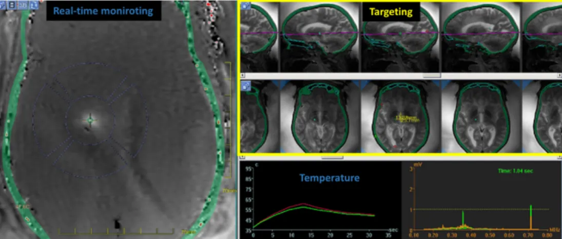
1.1. MAGNETIC RESONANCE IMAGING GUIDED HIFU 23 1.1 (Graphical interface of InsightecT M software) shows a real-time monitoring of MR-Thermometry during an MRgHIFU procedure on the brain. This treatment consists in ablating a pathological region of the brain causing essential tremors to the patient. In this procedure, a low temperature increase (< 4◦C) is used to local-ize the focus position, and during the ablation, the temperature evolution defines the therapy end-point.
In terms of sonication patterns, thermal effects often require high sonication duty cycles and high acoustic powers, in order to compete with cooling factor such as the perfusion (see WbCb term in equation 1.1). For moving organs, motion correction
of the position of the focus is often mandatory to preserve surrounding tissues and enhance the heating efficiency at the desired location [8, 9, 10, 11, 12].
Figure 1.1: Screenshot of a focused ultrasound brain sonication showing anatomical and real-time thermal data.
Mechanical effects: This strategy exploits the ultrasound cavitation effects to promote bioeffects, while preserving the underlying tissue. Acoustic cavitation mediates US’s tissular effects through three potential mechanisms [13]. One of these mechanisms is microstreaming. It describes the transmission of shear stress from fluid motion generated by oscillating bubbles at the ultrasound frequency, to cell membranes and endothelial surfaces (stable cavitation). Another mechanism is jetting from asymmetric collapse of a bubble (inertiel cavitation). Jetting of bubbles from vessel lumen into tissue, or from tissue into the lumen, can potentially increase vascular permeability and allows therapeutic agents to enter the cells. Cells permeability may also be enhanced by expanding and compressing bubbles in direct contact with its surface. Even-though mechanical effects tend to preserve the underlying tissue, these mechanisms could also lead to soft tissue damages when inertial cavitation becomes predominant. This is particularly the case during jetting, where temperature and
local pressures can reach extreme values.
However, with careful titration of US parameters, non-thermal effects can be ex-ploited for therapeutic purposes. Compared to thermal effects, mechanical effects usually involves low/medium acoustic power deposition. In the literature, it has been shown to promote beneficial bioeffects such as drug delivery [14], thrombolysis [15, 16], disruption of the blood brain barrier [17, 18], cardiac stimulation [19, 20] and neuro stimulation [21, 22].
As of today, mechanical and thermal applications of MRgHIFU on the brain are clearly identified and their feasibility is now widely accepted. Other organs such as the heart, could also benefit from similar approaches (i.e. thermal and mechanical effects). The main objective of this thesis work is to develop methods and evaluate the feasibility of cardiac applications of therapeutic ultrasounds. MRI will be used for real-time targeting and monitoring as well as for safety assessments. We have tried during this work to target cardiac applications with a clear relevance in cardiology and with concrete clinical perspectives. The following of this chapter will give a quick overview on the heart and on cardiac electrophysiology. Then, based on clinical needs and possible gain for the patient, several applications of ultrasounds on the heart are presented.
1.2
The heart
The heart is composed of four chambers, two atria and two ventricles. The right heart collects the venous blood and sends it to lungs for blood reoxygenation.Then, the blood comes back in the left atrium and is transferred to the left ventricle in order to be expelled in rest of the body. The separation of atria and ventricles is made by valves in order to ensure the blood transfer into the different cavities (Figure 1.2).
1.2. THE HEART 25
Figure 1.2: Anatomy of the anterior surface of the heart in cross section. The heart is divided into four heart chambers : two atria and two ventricles separated by the septum. LV ejects blood to the aorta to ensure blood perfusion of the body. The RV pushes blood through the pulmonary arteries to the lungs for blood reoxygenation.
1.2.1
Cardiac electrophysiology
The cardiac contraction of the heart is driven by the propagation of an electric wave. Cardiac electrophysiology (EP) is the study of this electrical system. The heart has a cardiac automatism which confers its properties of spontaneous and regular contraction at about 65-90 beats per minutes for an healthy patient at rest. In physiological conditions also referred as sinus rhythm, the electrical activity is initiated at the sinoatrial node (SAN) and propagates toward the atrioventricular node (AVN). During the propagation of the wave, cardiomyocytes of atria are successively electrically depolarized that triggers their mechanical contractions. Then the electrical wave follows the left and right bundle brunch and purkinje fibers in order to depolarize the ventricles (see Figure 1.3).
Figure 1.3: Electrical conduction system of the heart. Schematic representation of the heart chambers and conduction pathways. The home of cardiac automatism is at the SAN . The wave of depolarization spreads to both atria and converges to the AVN . Then, it propagates in the His bundle, which splits into two branches for each ventricle and arborizes in many branches called Purkinje fibers.
1.2.2
Electrocardiogram
Figure 1.4: Position of three electrodes for ECG recording
There are numerous ways to explore cardiac electro-physiology, the gold standard electrophysiological exam in clinic being the 12 derivations ElectroCardioGram (ECG). However a simpler configuration is the two derivations ECG. It has the advantage of being non-invasive and easily achievable with the use of 3 electrodes positioned on the chest (see Figure 1.4). On the ECG trace the activity of the different cardiac chambers can be observed. The ECG trace is thus a good surrogate for cardiac activity. Figure 1.5 presents a schematic representation of one derivation of an ECG. Several peaks can be depicted: termed the P, Q, R, S and T waves.
Figure 1.5: QRS complex. Schematic representation of an ECG recording
• P wave corresponds to the depolarization of the atria.
• PQ or PR interval represents the electrical conduction delay between the NAV and branches of the bundle of His.
• QRS complex depicts the depolarization of both ventricles. Note that repolar-ization of the atria occurs during this period of time and is often hidden by the
1.2. THE HEART 27 amplitude of the QRS complex.
• ST segment indicates the period during which the ventricular contractile fibers are completely depolarized and no depolarization can occur.
• T wave corresponds to ventricular repolarization. After this wave, the heart is in resting state before a new depolarization.
In the context of cardiac MRI, the ECG trace is used to synchronize the MR-acquisition on cardiac rhythm by detecting the R wave of the QRS complex (see Figure 1.5). If MR-acquisitions are fast and if they are always performed at the same time point within the cardiac cycle, the heart motion can be artificially frozen on resulting images. Note that cardiac contraction occurs predominantly during the QT interval, called systole, and the rest of the cardiac cycle, termed diastole, is the resting state of the heart. ECG gating in diastole is thus widely-used in cardiac MRI and in interventional MRI, as it can avoid motion of the target during treatment monitoring (see section 2.2.5.2 for more details).
Despite its good ability to characterize cardiac contraction state, the ECG trace turns out to be insufficient for a precise cardiac diagnosis. It only gives an ”averaged” ac-tivity of the heart due to its non localized feature. In addition, the torso acts as low-pass filter, which avoids precise electrical activity measurement of the local depolariza-tion/repolarization.
1.2.3
Catheters
To overcome the lacks of the ECG trace to perform precise electrophysiology mea-surements at the desired locations, cardiac catheters have been developed. Catheter are medical devices used to map electrical activity of the heart. The catheter is inserted under mini-invasive access inside vascular routes, in order to reach heart cavities. This proce-dure is routinely performed under x-ray guidance. To reach the LV or RV, the catheter can be inserted in the femoral artery or in the femoral vein, respectively. A catheter is usually made up of two to four electrodes but multiple electrodes systems are constantly developed to map more efficiently the 3D electrical activity of a cardiac chamber.
Figure 1.6: Electro-physiological catheter. The catheter is inserted in vascular routes to reach heart cavities. Once in contact with the cardiac wall, electric activity of this region can be measured.
1.2.4
Cardiac stimulation
In previous section (section 1.2.1), we have seen that cardiac contractions are induced by an electrical depolarization initiated by the SAN, which propagates to the rest of the heart. Similarly to the SAN, it is possible to induce a local depolarization anywhere in the heart by sending an external stimulus, such as an electrical impulse. Then, this local depolarization propagates, following the cardiac conduction pathways. To produce this local depolarization, an electrical lead can be inserted inside a cardiac cavity and put in contact with the cardiac wall. The other end is connected to a pacemaker (see Figure 1.8 D and F). Typical pulse settings to produce a stimulation are a duration of 1-2 ms and an amplitude of 5-10 Volts for the ventricles. Note that cardiac stimulation can only occur during a specific timing window in the cardiac cycle. When cardiomyocytes are depolarized (i.e. ST segment) no stimulation can be induced. This is called the refractory period (see red box on Figure 1.7). After the T wave, the cardiomyocytes are repolarized and can be stimulated again. This period is referred as the non refractory period (see green box on Figure 1.7).
1.2. THE HEART 29
Figure 1.7: Refractory and non refractory periods. Red and green box represent the refractory period and the non refractory period, respectively.
It is possible to repeat this stimulation over several repetitions (at a fixed frequency). This procedure is called continuous cardiac pacing. If the pulse frequency is greater than the SAN activity, electrical impulses will overdrive the SAN activity and force the heart to beat a the same frequency. In clinic, pacing can be performed on the atria, on a single ventricle or on both ventricles (see Figure 1.8A,B and C).
Figure 1.8: Pacing examples. A, Atrial pacing. B, Ventricular pacing. C, Dual-chamber pacing (atrial and ventricular pacing). Each asterisk represents a pacemaker impulse.
1.2.5
Abnormal conduction pathways
As described in section 1.2.1, for healthy subjects, the electrical conduction pathway is well organized and regular. However in pathological conditions, the heart conduction pathways can be deeply modified, altering its capacity to pump blood to the rest of the body. Origins of arrhythmias are numerous: it can involve arythmogenic subtrates [23],
conduction abnormalities [24] or can result from environmental factors. Figure 1.9 shows different types of ventricular arrhythmias:
Tachycardia corresponds to a increase in heart rate.
Fibrillation is a complete and permanent disorganized electrical activity of the heart. In this condition, the heart does not pump blood anymore and its defibrillation is the only way to restore the cardiac function.
Heart failure occurs when the heart is unable to pump blood sufficiently to maintain blood flow to meet the body’s needs. Common cause of heart failure is ventricular dyssynchrony. This cardiomyopathy is diagnosed in patient with a QRS complex larger than 120 ms and reduced ejection fraction (lower than 35 %).
Figure 1.9: Examples of cardiac arrhythmias. ECG recordings in sinus rhythm (A), during a ventricular tachycardia episode (B) and ventricular fibrillation (C).
Atrioventricular block is a failure of the AVN. The conduction pathway from the atria to the ventricles is not functional anymore. Patients suffering from this disease have often a slow and irregular rhythm which results from the capacity of regions in the ventricles to trigger local depolarizations (ectopic foci). This rhythm is called the escape rhythm. Due to the severe bradycardia, these patients are often in really bad conditions.
Cardiovascular disease is the first cause of mortality in the whole world. In 2008, the world health organization reported that it is responsible for 29% of deaths, followed
1.3. POTENTIAL APPLICATIONS OF HIFU ON THE HEART 31 by infectious diseases (16.2%) and cancers (12.6%)1. The economic burden related to cardiac diseases will grow with the ageing European population making cost management of Public Health more challenging.
1.3
Potential applications of HIFU on the heart
1.3.1
Application 1: Cardiac ablation
1.3.1.1 Clinical context
Radiofrequency ablation is a medical procedure used in cardiology for the treatment of a number of cardiac rhythm disorders and complements antiarrhythmic drug thera-pies. This surgical procedure consists in eliminating ectopic depolarisation foci (local depolarization) or undesired conduction pathways. To this end, a catheter is inserted in contact with the myocardium, under X-ray guidance to burn the abnormal conductions sites. For the treatment of atrial tachysystolia or certain ventricular tachycardias, a pre-liminary step consists in mapping the electrical activity of the heart using catheters to identify pathological regions. Then, a 3D rendering of parametric electrical signals (am-plitude, frequency,...) is performed on a dedicated software (Figure 2-E) such as NavX (St Jude Medical, St Paul, MI, U.S.A.) or CARTO (BiosenseWebster, Diamond Bar, CA, U.S.A.), in order to assist the clinician during the ablation. The therapeutic outcome of the ablation depends highly on the identification of origin sites of the arrhythmia.
Figure 1.10: Radiofrequency ablation. a) 3D mapping of an artia using a CARTO. Red dots represent the ablation points. b) Isolation of pulmonary veins using a catheter inserted in the heart cavity. c) Schematic representation of an radiofrequency ablation procedure
1.3.1.2 MRgHIFU for cardiac ablations
As for now, combining an HIFU device and MRI for cardiac ablations is a major step forward compared to the current patient care or even current preclinical studies. However, their gains for the improvement of ablation therapies have been demonstrated indepen-dently. For instance, studies have inverstigated HIFU ablations under X-ray [25, 26], and some others have monitored the temperature evolution during radiofrequency ablation under MRI[27, 28, 29]. Combining both methods could potentially bridge therapeutic dead-ends and provide the operator with new information on the intervention process. MR-monitoring versus X-ray guidance: Compared to X-ray, MRI has a greater soft
tissue contrast, which allows precise targetting of the pathological cardiac tissue. In addition, as proposed by De Senneville et al. [28] real-time monitoring of the procedure could be performed using MR-thermometry, which has proven its ability to predict the lesion size, while controlling the energy delivered. Finally, 3D post-ablation imaging can attest the extension of the lesion and could give insights of the need of other ablation point. As of now, MRI is the only imaging modality that provides imaging at every stages of the ablation procedure.
HIFU versus radiofrequency ablation Compared to radiofrequency ablation, HIFU ablation has the possibility to target deeper cardiac tissues and can be made non-invasive (see epicardial catheter ablation on Figure 1.11, extracted from [26] ). As shown in Figure 1.11, for radiofrequency ablations the catheter tip has to be in contact with the tissue to deliver the electric power. As a consequence, the lesion enlarges from this contact (see Figure 1.10c) with limited ability to reach the other side of the cardiac wall for cardiac wall thickness of 1 cm and more in the LV. In this context, common strategies to improve lesion sizes are: to increase electric power de-livery and/or lengthen the ablation duration. These strategies are accompanied with possible adverse effects which are: induction a coagulum, which prevents deeper ab-lations, or increase the risk of steam pop resulting in cardiac perforations [30]. Also note that application of radiofrequency energy on the epicardium is often limited by epicardial fat that reduces electrical current intensity, or proximity to the phrenic nerve or coronary arteries present on the epicardium [31]. The hot spot generated by an HIFU ablation is located at the focus of the transducer, without the need of a physical contact with the cardiac tissue to be treated. The only requisite is an ultrasound coupling, from the transducer to the target. As shown by 1.11, HIFU
1.3. POTENTIAL APPLICATIONS OF HIFU ON THE HEART 33 ablation shapes could be more suited to perform transmural ablations or target the endocardium or the epicardium, respectively.
Figure 1.11: Ablation comparison Representative high-intensity ultrasound (HIU) and radiofrequency (RF) epicardial lesions. Triphenyl-2H-tetrazolium chloride–stained cross-sections of left ventricular myocardium shown with epicardial surface on top.
Technological considerations apart, cardiac ablations under MRI using an external HIFU device could allow non-invasive ablation of cardiac muscle, while providing biomark-ers monitoring such as temperature and/or displacement. Finally, post-ablation imaging would attest the resulting lesion extension from consecutive individual ablations
1.3.2
Application 2: Heart failure and cardiac pacing
1.3.2.1 Clinical context
Current patient treatment for heart failure consist in electrical pacing of the heart using a pacemaker. To this end, a surgical approach is done under x-rays guidance to insert electrical leads into heart cavities (see Figure 1.12). Lead placement depends on the patient disease but most often a lead is placed in a coronary sinus for LV pacing in addition to a conventional RV endocardial lead. This therapy is referred as the resynchronization therapy [32]. In France, patients suffering form heart failure in 2001 were 500 000, with 120 000 new cases each year [33].
Figure 1.12: Pacemaker implantation. One lead is placed in the right ventricle. A second one inserted in the coronary sinus, passing though the right atria, for left ventricular pacing.
This procedure is currently the gold-standard for the treatment of this disease. Even though clear improvement of patient condition have been demonstrated, there are still 1/3 whom are non-respondent. In addition, several limitations are inherent to this surgical procedure:
• Newborn patients and patients with infections cannot be implanted.
• Operating room and medical staff have to be available. This can be problematic when patients arrive in emergency.
• During pacemaker replacement, patient is not paced anymore.
As of now, for clinical contraindications mentioned earlier, temporary pacing has to be performed to prevent patients death. Indeed, the two most common reasons for using temporary pacing is to maintain an optimal cardiac output when patients have developed a symptomatic bradycardia or are asystolic. Two temporary pacing methods are currently available in clinic [34]:
Temporary pacing using a catheter. An electrical lead is inserted through vascular routes to pace the heart [35]. However, several complications are observed during long duration catheter pacing. The two greatest are: a loss of capture as the catheter in not in contact with the myocardium, and the risk of heart perforation if the catheter is inserted too far into the cavity.
Transcutaneous cardiac electrical pacing. This procedure consists in stimulating the heart using electrodes positioned on the patient’s chest [36, 37]. Simulation in this manner, is often not well accepted by patient due to discomfort of muscle stimulation.
1.4. CHALLENGES OF CARDIAC APPLICATION OF HIFU THERAPIES 35 1.3.2.2 Non-invasive cardiac pacing using HIFU
One application of mechanical effect of ultrasounds on the heart is to produce pre-mature cardiac contractions [19, 20]. Its application would benefit highly in clinical cardiology and electro-physiology as it would allow non-invasive stimulation of targeted areas of the myocardium using an extra-corporeal non electric energy and could be used for diagnostic as well as therapeutic purposes. Such an ultrasound system, with all of its components external to the body, would not require any surgical or catheterization procedures, implanted receivers, or intra-vascular leads. It could hence, dramatically reduce device related complications, including vascular rupture, infection, and need for extraction.
1.4
Challenges of cardiac application of HIFU
ther-apies
During this thesis, we have envisioned fully non-invasive applications of therapeutic ultrasounds on the heart. Two applications are targeted: non-invasive cardiac ablation and non-invasive cardiac stimulation. However fully non-invasive cardiac applications of ultrasounds are particularly challenging as they combine two well-known limitations of ultrasounds: namely motion of the target and the capacity of ultrasounds to propagate through the thoracic cage.
1.4.1
Motion
The motion of the heart is complex and has two main components: one due to the respiration and an other due to cardiac contractions. Both motion components are asyn-chronous with different amplitudes, directions and speeds.
1.4.1.1 Respiratory motion
The heart lays upon the liver which moves with the respiration due to inhalation and exhalation of air in lungs. Breathing induces predominantly a translation of the heart in the head-feet direction at a rate ranging from 10 to 15 breaths per minute with amplitudes from 1 to 2 cm [38].
1.4.1.2 Cardiac motion
Cardiac contractions occur at about one beat per minute. As compared to respiratory motion, cardiac motion is more complex. There are three components of motion in cardiac contraction: first a radial and longitudinal component of contraction combined with a twist along its longitudinal direction [39]. Note that the heart is at resting state during a limited period of time, around 200-300 ms during the diastole.
1.4.2
Anatomical structures and acoustic windows
Many anatomical structures, with very poor ultrasound propagation capabilities, are included in the beam path, before reaching the heart. The main constrain is the thoracic cage, which surrounds the heart and acts as an aberration, decreasing the focusing quality of the ultrasonic beam [40, 41]. Other organs such as lungs, positioned from each side of the heart, and on its posterior side, reduce even more the acoustic window available. In summary, only intercostal acoustic windows could propagate ultrasound waves with a good efficiency. Nevertheless, the acoustic window varies greatly during respiratory cycle and also change according to the position of the patient. This adds more complexity to target a precise location of the heart.
1.4.3
Review of cardiac therapeutic ultrasound
Cardiac applications of therapeutic ultrasounds have been explored since early 90’s. Table 1.1 sums up some of cardiac applications of HIFU, divided in two categories: thermal applications and mechanical applications.
Cardiac ablation using HIFU could potentially bridge current limitations of radiofre-quency ablations (as introduced in section 1.3.1.2). However, only two studies have demonstrated the feasability of a fully non-invasive cardiac ablation in vivo, in dog [42, 43]. This observation highlights the complexity of non-invasive approaches on the heart (limited acoustic window, anatomical structures, motions). This is all the more so, when long duration HIFU exposures are required. In others in vivo studies, a mini-invasive ap-proach is preferred (Trans-oesophagus [44] or catheters [26] ) or midline sternotomy [45]. These approaches allow to circumvent transthoracic sonications and optimize the ultra-sound power deposition. Nevertheless, catheter apart, ultraultra-sound ablations might remain suboptimal in absence of physiological motion compensations and real-time update of the focus position.
1.5. CONTEXT OF THIS THESIS 37 Several mechanical applications of ultrasounds have been proposed in the literature. Overall, they also suffer from the same aforementioned limitations. Note that some ap-plications such as the treatment of thrombolysis or angiogenesis [46, 47], tend to be cumulative over sonication repetitions. In these cases, the delivery of therapeutic ul-trasounds should hence be easier to achieve. For cardiac stimulations, several studies have investigated the feasibility on small animal models. Nevertheless, given the acoustic power needed to depolarize the heart, it may require some ingenuity and technological developments to translate this application toward large animal models.
Authors Methods
Thermal
effect
Bessiere et al. 2016 [44] In vitro Trans-oesophagus prob for cardiac abla-tion
Zheng et al. 2014 [42] In vivo (dog) HIFU myocardial ablation and bio-logical response
Laughner et al 2012 [48] Ex vivo HIFU myocardial ablation on wedge prep Schopka et al. 2010 [45] In vivo (Humain patients) AF ablation with
ultra-sound probe
Strickberger et al. 1999 [49] Ex vivo HIFU myocardial ablation
Mec
hanical
effect
Unger et al. 2014 [14] Cardiovascular drug delivery with ultrasound and microbubbles (clinical trial)
Livneh et al. 2014 [19] In vivo (rat) cardiac stimulation and passive cavi-tation detection
Hanawa et al. 2009 [47] Pulsed Ultrasound Induces Angiogenesis and Ame-liorates Left Ventricular Dysfunction (pig)
Wright et al. 2012 [46] In vitro and in vivo HIFU thrombolysis (rabbit) Dalecki et al 1991 [50] In vivo (frog) cardiac stimulation
Table 1.1: Publications in the field of cardiac applications of therapeutic ultrasounds
1.5
Context of this thesis
This thesis was granted by the company Image Guided Therapy via a CIFRE contract with ”L’Institut de RYthmologie et Mod´elisation Cardiaque” in Pessac. This institute is one of the six ”Institut Hospitalo-Universitaire” in France, and it is dedicated to heart diseases. The bulk of the thesis work, focused on the application of MRgHIFU on the heart using fully non-invasive HIFU devices. At the beginning of the thesis, an HIFU
device and an MRI were available but without any technological development toward this application. The thesis can be coarsely divided in two parts.
Cardiac stimulation: Investigation of the clinical applications of using HIFU to per-form non-invasive cardiac stimulation in a preclinical large animal model (Chapter 3).
Methodological developments: These developments were required for non-invasive cardiac ablation and stimulation. It consisted first, in novel monitoring methods combining MR-temperature and MR-ARFI (Chapter 4) for ablations monitor-ing and/or safety assessments. The second methodological development concerned the management of the physiological motions during MR-thermometry monitoring and correction of the focus position for MRgHIFU applications on moving organs (Chapter 5).
1.6
References
[1] Jean-Michel Escoffre and Ayache Bouakaz, eds. Therapeutic Ultrasound. Advances in Experimental Medicine and Biology. Cham: Springer International Publishing, 2016.
[2] Bruno Quesson et al. “Real-time volumetric MRI thermometry of focused ultra-sound ablation in vivo: a feasibility study in pig liver and kidney”. en. In: NMR in Biomedicine (Feb. 2011).
[3] Nathan McDannold and Stephan E. Maier. “Magnetic resonance acoustic radiation force imaging”. In: Medical Physics (2008).
[4] T. Leslie et al. “High-intensity focused ultrasound treatment of liver tumours: post-treatment MRI correlates well with intra-operative estimates of post-treatment volume”. en. In: British Journal of Radiology (Jan. 2012).
[5] P. N. T. Wells. “Absorption and dispersion of ultrasound in biological tissue”. In: Ultrasound in Medicine & Biology (Mar. 1975).
[6] Stephen A. Sapareto and William C. Dewey. “Thermal dose determination in cancer therapy”. In: International Journal of Radiation Oncology*Biology*Physics (Apr. 1984).
1.6. REFERENCES 39 [7] Samantha Ellis et al. “Clinical applications for magnetic resonance guided high intensity focused ultrasound (MRgHIFU): Present and future: Clinical applications for MRgHIFU”. en. In: Journal of Medical Imaging and Radiation Oncology (Aug. 2013).
[8] Baudouin Denis de Senneville et al. “Real-time adaptive methods for treatment of mobile organs by MRI-controlled high-intensity focused ultrasound”. en. In: Mag-netic Resonance in Medicine (Feb. 2007).
[9] Mario Ries et al. “Real-time 3D target tracking in MRI guided focused ultrasound ablations in moving tissues”. en. In: Magnetic Resonance in Medicine (Dec. 2010). [10] W. Apoutou N’Djin et al. “An ultrasound image-based dynamic fusion modeling method for predicting the quantitative impact of in vivo liver motion on intraoper-ative HIFU therapies: Investigations in a porcine model”. In: PloS one (2015). [11] Zarko Celicanin et al. “Real-time method for motion-compensated MR thermometry
and MRgHIFU treatment in abdominal organs: MRgHIFU Treatment Method in Abdominal Organs”. en. In: Magnetic Resonance in Medicine (Oct. 2014).
[12] Philippe Louren¸co de Oliveira et al. “Rapid motion correction in MR-guided high-intensity focused ultrasound heating using real-time ultrasound echo information”. en. In: NMR in Biomedicine (Nov. 2010).
[13] H. G. Flynn. “Generation of transient cavities in liquids by microsecond pulses of ultrasound”. In: The Journal of the Acoustical Society of America (Dec. 1982). [14] Evan Unger et al. “Cardiovascular drug delivery with ultrasound and microbubbles”.
en. In: Advanced Drug Delivery Reviews (June 2014).
[15] Kathryn E. Hitchcock et al. “Ultrasound-Enhanced rt-PA Thrombolysis in an ex vivo Porcine Carotid Artery Model”. en. In: Ultrasound in Medicine & Biology (Aug. 2011).
[16] Saurabh Datta et al. “Ultrasound-Enhanced Thrombolysis Using Definity as aR
Cavitation Nucleation Agent”. en. In: Ultrasound in Medicine & Biology (Sept. 2008).
[17] Alison Burgess and Kullervo Hynynen. “Drug delivery across the blood–brain barrier using focused ultrasound”. en. In: Expert Opinion on Drug Delivery (May 2014).
[18] Fabrice Marquet et al. “Real-Time, Transcranial Monitoring of Safe Blood-Brain Barrier Opening in Non-Human Primates”. en. In: PLoS ONE (Feb. 2014). Ed. by Stefan Liebner.
[19] Amit Livneh et al. “Extracorporeal acute cardiac pacing by High Intensity Focused Ultrasound”. en. In: Progress in Biophysics and Molecular Biology (Aug. 2014). [20] Anat Hersch and Dan Adam. “Premature cardiac contractions produced efficiently
by external high-intensity focused ultrasound”. eng. In: Ultrasound in Medicine & Biology (July 2011).
[21] Thomas Deffieux et al. “Low-intensity focused ultrasound modulates monkey visuo-motor behavior”. eng. In: Current biology: CB (Dec. 2013).
[22] E. Rezayat and I. Ghodrati Toostani. “Review Paper: A Review on Brain Stimula-tion Using Low Intensity Focused Ultrasound”. In: Basic and Clinical Neuroscience Journal (2016).
[23] Michel Ha¨ıssaguerre et al. “Spontaneous Initiation of Atrial Fibrillation by Ectopic Beats Originating in the Pulmonary Veins”. In: New England Journal of Medicine (1998).
[24] David J Wilber et al. Catheter ablation of cardiac arrhythmias: basic concepts and clinical applications. English. OCLC: 608624157. Malden, Mass.: Blackwell, 2008. [25] Simon Schopka et al. “Ablation of atrial fibrillation with the Epicor system: a
prospective observational trial to evaluate safety and efficacy and predictors of suc-cess”. In: Journal of cardiothoracic surgery (2010).
[26] Babak Nazer et al. “Epicardial Catheter Ablation Using High-Intensity Ultrasound”. In: Circulation: Arrhythmia and Electrophysiology (2015).
[27] Aravindan Kolandaivelu et al. “Cardiovascular magnetic resonance guided electro-physiology studies”. en. In: Journal of Cardiovascular Magnetic Resonance (2009). [28] De Senneville et al. “Feasibility of fast MR-thermometry during cardiac
radiofre-quency ablation”. en. In: NMR in Biomedicine (Apr. 2012).
[29] Solenn Toupin et al. “Feasibility of real-time MR thermal dose mapping for pre-dicting radiofrequency ablation outcome in the myocardium in vivo”. In: Journal of Cardiovascular Magnetic Resonance (Jan. 2017).
[30] Hubert Cochet et al. “Steam pop during radiofrequency ablation”. In: Circulation: Arrhythmia and Electrophysiology (2014).
1.6. REFERENCES 41 [31] Jacob S. Koruth et al. “Unusual complications of percutaneous epicardial access and epicardial mapping and ablation of cardiac arrhythmias”. eng. In: Circulation. Arrhythmia and Electrophysiology (Dec. 2011).
[32] Kenneth A. Ellenbogen, ed. Clinical cardiac pacing, defibrillation, and resynchro-nization therapy. eng. 4. ed. OCLC: 774433798. Philadelphia, PA: Elsevier/Saunders, 2011.
[33] F. Delahaye et al. “[Epidemiology and prognosis of cardiac insufficiency]”. fre. In: Archives Des Maladies Du Coeur Et Des Vaisseaux (Dec. 2001).
[34] Michael D. Gammage. “Temporary cardiac pacing”. In: Heart (2000).
[35] Robert G. Tancredi et al. “Temporary transvenous catheter-electrode pacing of the heart”. In: Circulation (1967).
[36] B. Gamrath et al. “Noninvasive pacing: what you should know”. eng. In: Journal of emergency nursing: JEN: official publication of the Emergency Department Nurses Association (June 1998).
[37] E Rosenthal et al. “Transcutaneous pacing for cardiac emergencies.” In: Pacing and clinical electrophysiology : PACE (1988).
[38] S. C. Davies et al. “Ultrasound quantitation of respiratory organ motion in the upper abdomen”. In: The British journal of radiology (1994).
[39] Tetsuya Horiuchi et al. “Heart motion measurement with three dimensional sonomi-crometry and acceleration sensing”. In: IEEE, Oct. 2012.
[40] Hao-Li Liu et al. “Focal beam distortion and treatment planning in abdominal focused ultrasound surgery”. In: Medical Physics (2005).
[41] Svetlana Bobkova et al. “Focusing of High-Intensity Ultrasound Through the Rib Cage Using a Therapeutic Random Phased Array”. en. In: Ultrasound in Medicine & Biology (June 2010).
[42] Minjuan Zheng et al. “High-Intensity Focused Ultrasound Ablation of Myocardium In Vivo and Instantaneous Biological Response”. en. In: Echocardiography (Oct. 2014).
[43] Shunkang Rong et al. “Septal Ablation Induced by Transthoracic High-Intensity Focused Ultrasound in Canines”. In: Journal of the American Society of Echocar-diography (Oct. 2013).