HAL Id: tel-01303407
https://tel.archives-ouvertes.fr/tel-01303407
Submitted on 18 Apr 2016HAL is a multi-disciplinary open access archive for the deposit and dissemination of sci-entific research documents, whether they are pub-lished or not. The documents may come from teaching and research institutions in France or abroad, or from public or private research centers.
L’archive ouverte pluridisciplinaire HAL, est destinée au dépôt et à la diffusion de documents scientifiques de niveau recherche, publiés ou non, émanant des établissements d’enseignement et de recherche français ou étrangers, des laboratoires publics ou privés.
Video compression based on smart decoder
Dang Khoa Vo Nguyen
To cite this version:
Dang Khoa Vo Nguyen. Video compression based on smart decoder. Other. Université Nice Sophia Antipolis, 2015. English. �NNT : 2015NICE4136�. �tel-01303407�
UNIVERSITE NICE-SOPHIA ANTIPOLIS
ECOLE DOCTORALE STIC
SCIENCES ET TECHNOLOGIES DE L’INFORMATION ET DE LA COMMUNICATION
T H E S E
p
our l’obtention du grade de
Docteur en Sciences
d
e l’Université Nice-Sophia Antipolis
Mention : Automatique, Traitement du Signal et des Images
présentée et soutenue par
Dang Khoa VO NGUYEN
Compression vidéo basée sur
l’exploitation d’un décodeur intelligent
Thèse dirigée par
Marc ANTONINI, Directeur de Recherche, CNRS
Equipe d’accueil : Laboratoire I3S, UNS-CNRS
et
Joël JUNG, Ingénieur de Recherche, Orange Labs
Equipe d
’accueil : CVA, Orange Labs
soutenue le 18/12/2015
Jury :
Amel BENAZZA-BENYAHIA Ecole Supérieure des Communications de Tunis, Tunisie Rapporteur Marco CAGNAZZO CNRS-Télécom ParisTech, France Rapporteur Marc ANTONINI CNRS-Université Nice-Sophia Antipolis, France Directeur de thèse Joël JUNG Orange Labs, France Encadrant de thèse
Jean-Luc DUGELAY Eurecom, France Examinateur
Remerciements
T
outd’abord, je tiens à exprimer ma sincère gratitude à mon encadrant de thèse, Dr. Joël JUNG, pour son soutien dans ma recherche pendant les trois années de doctorat, pour sa patience, sa motivation et son ent-housiasme. C’est grâce à sa direction et son immense compétence que j’ai pu progresser dans ma recherche et dans la rédaction de ce manuscrit. Son oeil critique m’a été très précieux pour structurer le travail et pour améliorer la qualité des travaux réalisés.Je tiens aussi à remercier mon directeur de thèse, Marc ANTONINI, pour son soutien, ses observations judicieuses, ses idées intéressantes et ses suggestions constructives. Qu’il trouve ici l’expression de ma profonde reconnaissance
Je tiens également à remercier Amel BENAZZA-BENYAHIA, pro-fesseur à l’Ecole Supérieure des Communications de Tunis, et Marco CAGNAZZO, maitre de conférence à CNRS-Télécom ParisTech, d’avoir accepté d’être les rapporteurs de ce manuscrit. Je remercie Jean-Luc DUGELAY, professeur à Eurecom, et Luce MORIN, maitre de conférence à INSA Rennes, d’avoir accepté d’évaluer ce travail de thèse.
Mes sincères remerciements vont aussi à toute l’équipe de Compres-sion Vidéo Avancée d’Orange Labs. J’ai passé de très agréables moments avec vous lors des réunions d’équipes à Rennes. Je souhaite remercier particulièrement mon manager Didier GAUBIL pour ses encouragements ainsi que son aide pour des problèmes administratifs.
Je remercie mes collègues de bureau: Kartik, Elie, et Antoine pour les discussions stimulantes et pour tout le plaisir que nous avons eu au cours de ma thèse. J’ai beaucoup apprécié leur compétences et leur aide qui m’ont permis à progresser dans ma recherche.
Finalement, je tiens à remercier ma famille et mes parents pour m’avoir soutenir spirituellement tout au long de ma vie. Aucun mot ne peut ex-primer ma gratitude envers ma mère qui a sacrifié toute sa vie pour ma réussite.
Table of Contents
Table of Contents vii
List of Figures xi
List of Tables xvi
List of Acronyms xxi
Introduction 1
1 Video coding and HEVC standard 5
1.1 Context . . . 7 1.2 HEVC standard . . . 7 1.2.1 Coding stucture . . . 7 1.2.2 Intra prediction . . . 9 1.2.3 Inter prediction . . . 11 1.2.4 Residual coding . . . 13 1.2.5 Other tools . . . 13 1.3 3D-HEVC standard . . . 15 1.3.1 Coding structure . . . 15 1.3.2 Disparity-Compensated Prediction (DCP) . . . 16
1.3.3 Inter-View Motion Prediction (IVMP) . . . 17
1.3.4 Sub-PU Inter-View Motion Prediction (SP-IVMP) . . . 17
1.3.5 Advanced Residual Prediction (ARP) . . . 18
1.4 Video coding techniques exploiting a complex decoder 19 1.4.1 Basic decoder to a more complex decoder with joint com-putation . . . 19
1.4.2 Complex decoder with R-D competition . . . 20
1.5 Improvement techniques related to our works . . . 21
1.5.1 Intra 1D . . . 21
1.5.2 Warped Optical Flow (WOF). . . 22
1.5.3 Machine learning based approaches . . . 23
1.5.3.1 Overview on machine learning . . . 24
1.5.3.2 Video coding techniques based on machine learning . . . 25
Conclusion . . . 26
2 Video coding scheme based on Smart Decoder (SDec) 31 2.1 Motivation . . . 33
2.2 General description of SDec based video coding scheme 34 2.2.1 Encoding scheme . . . 35
2.2.2 Decoding scheme . . . 37
2.3 Advantages and drawbacks of the SDec design . . . 38
2.4 Selection of the SDec reference . . . 39
2.5 Partial standardization of the encoder using the SDec scheme . . . 43
Conclusion . . . 44
3 SDec based coding scheme using Intra mode 45 3.1 Description . . . 47
3.2 A study on different parameters of proposed scheme . 48 3.2.1 Signaling method for the SDec flag . . . 48
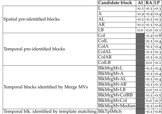
3.2.2 Block candidates for the SDec reference . . . 51
3.2.3 Number of Intra directions used in the SDec competition 54 3.2.4 Number of candidates for the SDec reference . . . 56
3.2.5 Selection of the SDec reference based on the Intra most probable modes. . . 62
3.3 Best configuration . . . 64
3.3.1 Experimental results . . . 64
3.3.2 Statistical analysis . . . 65
3.3.2.1 SDec selection rate . . . 65
3.3.2.2 Coding modes replaced by SDec mode . . . 66
3.4 Perspectives . . . 67
Conclusion . . . 68
4 SDec based coding scheme using Intra 1D mode 69 4.1 Implementation of Intra 1D . . . 71
4.2 Analysis on different parameters of Intra 1D . . . 72
4.2.1 Direction of 1D-partitions . . . 72
4.2.2 Selection of scan order for 1D-partitions . . . 74
4.2.3 Number of Intra directions for 1D-partitions . . . 76
4.2.4 Analysis of the impact of Intra 1D on HEVC Intra . . . . 77
4.2.5 Best configuration . . . 78
4.3 Intra 1D used as a coding mode in the SDec scheme . . 80
4.3.1 Description . . . 80
4.3.2 Parameters related to the SDec reference . . . 82
4.3.3 Selected SDec configurations. . . 85
4.3.4 Statistical analysis . . . 87
4.4 Perspectives . . . 89
Conclusion . . . 89
5 SDec based coding scheme inheriting re-estimated mo-tion parameters 91 5.1 General description . . . 93
5.2 Advantages and drawbacks . . . 93
5.3 Implementation with motion parameters re-estimated using block matching technique . . . 94
5.3.1 Description . . . 94
5.3.2 Experimental results . . . 95
5.3.2.1 Selection of block to be the SDec reference 96 5.3.2.2 Search range for the block matching based motion re-estimation . . . 97
5.3.2.3 Position of the SDec reference in the Merge
list . . . 98
5.3.2.4 Best configuration . . . 99
5.3.3 Statistical analysis . . . 101
5.4 Implementation with motion parameters re-estimated usingOptical Flow technique . . . 101
5.4.1 Application in 2D coding . . . 101 5.4.1.1 Description . . . 101 5.4.1.2 Experimental results . . . 102 5.4.2 Application in 3D coding . . . 105 5.4.2.1 Description . . . 105 5.4.2.2 Implementation of WOF . . . 106
5.4.2.3 Competition between WOF and SP-IVMP . 107 5.4.3 Perspectives. . . 111
Conclusion . . . 112
6 SDec based coding scheme combining a multitude of coding modes 113 6.1 SDec scheme exploiting several coding modes applied in 2D . . . 115
6.1.1 Description . . . 115
6.1.2 Experimental results . . . 115
6.2 SDec scheme exploiting several coding modes applied in 3D . . . 118
6.2.1 Description . . . 118
6.2.2 Experimental results . . . 119
6.3 Improvement using adaptive selection depending on the visual content . . . 121
Conclusion . . . 123
7 Improvement for Intra MPM signaling scheme 127 7.1 Basic idea . . . 129
7.2 Preliminary observations . . . 129
7.3 Proposed method and experimental results . . . 130
7.4 Perspectives . . . 132
Conclusion . . . 134
8 Video coding scheme based on machine learning 135 8.1 Background . . . 137
8.1.1 Video coding methods based on machine learning . . . . 137
8.1.2 Exploitation of histograms as block features . . . 139
8.1.2.1 Using histogram as a local descriptor of blocks . . . 139
8.1.2.2 Using Bag-of-Feature framework as a global descriptor . . . 140
8.2 Proposed method . . . 142
8.2.1 General description. . . 142
8.2.2 Possible variants . . . 144
8.2.3 Features to be used in block classification . . . 145
8.3 Proposed practical applications . . . 146
8.3.1.1 Signaling scheme . . . 149
8.3.1.2 Selection of features to be exploited . . . . 150
8.3.1.3 Number of frames in training set . . . 151
8.3.1.4 Coding gain . . . 151
8.3.2 Application for classifying Intra MPM flags. . . 153
8.3.2.1 Signaling scheme . . . 153
8.3.2.2 Selection of features to be exploited . . . 153
8.3.2.3 Selection of training set . . . 154
8.3.2.4 Coding gain . . . 154
8.4 Perspectives . . . 156
Conclusion . . . 157
Conclusion and future works 159
Publications 163
Bibliography 165
List of Figures
1.1 Typical HEVC video encoder (with decoder modeling ele-ments shaded in light gray) (Source: (Sullivan et al. 2012)). . 8 1.2 GOP structures with different types of frame highlighted in
colors. Arrows indicate references of a frame. The number under each frame indicates its order of processing. (a) AI. (b) LP. (c) RA. . . 9 1.3 Subdivision of a CTB into CUs, PUs and TUs. Solid lines
indicates CU boundaries. Dashed lines indicates PU bound-aries. Dotted lines indicates TU boundbound-aries. . . 9 1.4 Modes and directional orientations for Intra prediction
(Source: (Sullivan et al. 2012)). . . 10 1.5 Intra MPM signaling scheme. . . 11 1.6 (a) Motion estimation. (b) Motion compensation. . . 12 1.7 Positions of possible MVP candidates for a current PU X. (a)
Spatial MVP candidate positions. (b) Temporal MVP candi-date positions, where Y is the collocated block of X in a reference picture (Source: (Helle et al. 2012)). . . 12 1.8 Computing the context initial value for a flag element
in-volves plotting the probability of this flag being equal to 1. . 14 1.9 A depth map with its associated texture frame. The higher
the luminance value (brighter), the closer the object is to the camera. . . 15 1.10 Intermediate synthesized views (V2, V3, V4) interpolated
from main views (V1, V5). . . . 16 1.11 Motion-compensated (red) and Disparity-compensated
pre-dictions (blue). . . 17 1.12 Correlation between motion vectors in base view and in
de-pendent view. . . 17 1.13 Inheritance of MVs on sub-PU level from base view to
de-pendent view in SP-IVMP . . . 18 1.14 Inheritance of MVs (red arrows) to compute residual
pre-dictor in Advanced Residual Prediction. . . 19 1.15 Video coding scheme with passive decoder. . . 20 1.16 Video coding scheme with active decoder able to perform
Template Matching process. . . 20 1.17 Video coding scheme with complex decoder able to perform
R-D competition. . . 21 1.18 Different shapes of 1D partitions, obtained by propagating
initial 1D-partition (in darkest color) (Source: (Thiesse et al. 2009)). . . 22
List of Figures
1.19 Different scan orders for 1D partitions in block (Source: (Laroche et al. 2009)). . . 22 1.20 DVMF computed using OF based on reconstructed frames
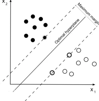
in base view at instant ti and ti−1 is inherited to encode a PU in dependent view at instant ti in Warped Optical Flow technique. . . 23 1.21 Maximum-margin hyperplane and margins for an SVM
trained with samples from two classes. . . 24 1.22 Compressing entire luminance frame (a) using
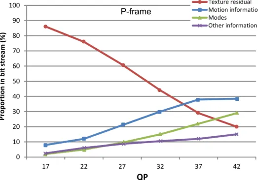
learn-ing method based on representative pixels (b) (Source: (Bai et al. 2009)). . . 25 1.23 Decision tree for Intra block partitions and directions. . . 26 2.1 Proportion in bit stream for different syntax elements in
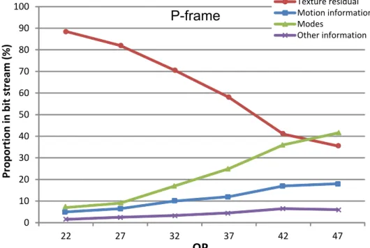
H.264/AVC. . . 33 2.2 Proportion in bit stream for different syntax elements in
HEVC. . . 34 2.3 Basic idea of the SDec scheme: use the optimal coding mode
computed on a causal reference P′ located in an already decoded frame at instant tj to encode the current block P located in the frame at instant ti. . . 35 2.4 General outline of the SDec encoding scheme. . . 36 2.5 General outline of the SDec decoding scheme. . . 38 2.6 Example of efficiently selecting blocks to be the SDec
refer-ence: being more similar to P than P2′, P1′ is a better choice. . 40 2.7 Example of efficiently selecting blocks to be the SDec
refer-ence: despite being less similar to P than P1′, P2′ is as efficient as P1′ since they both yield the same optimal Intra vertical direction. . . 40 2.8 Example of efficiently selecting blocks to be the SDec
refer-ence: being more similar to P than P2′ in transform domain,
P1′ is the better choice. . . 41 2.9 Wedgelet partition (top) and contour partition (bottom)
of a depth block: original sample assignment to parti-tions P1 and P2 (left) and partition pattern (right) (Source: (Muller et al. 2012)). . . 42 2.10 Scope of video coding standardization . . . 43 2.11 Partial standardization of the encoder to be compatible with
the SDec scheme. . . 43 3.1 Principle of the SDec scheme using Intra mode: optimal
In-tra direction computed on P′ in the already reconstructed frame at instant tj is inherited to encode P in the current frame at instant ti. . . 47 3.2 Signaling scheme for the introduced SDec syntax elements
in the SDec scheme using Intra coding mode . . . 48 3.3 Proposed pre-identified spatial neighboring blocks as SDec
reference candidates for the current block P in the frame at instant ti. . . 51
List of Figures
3.4 Proposed pre-identified temporal blocks in a reconstructed frame at instant tj as the SDec reference candidates for the current block P in the frame at instant ti. . . 52 3.5 The neighbor surrounding region of the n×n current block
located in the frame at instant ti is used as template with thickness e. . . . 53 3.6 Spiral template matching search order from pixel to pixel
within search region of radius r. . . . 53 3.7 Signaling scheme for sdec_re f syntax element in case of
multiple candidates for the SDec reference. . . 56 3.8 Signaling of sdec_re f in case of 2 candidates for the SDec
reference. . . 57 3.9 Signaling of sdec_re f in case of 3 candidates for the SDec
reference. . . 59 3.10 Sequence "ChinaSpeed_1024×768" with blocks encoded in
SDec mode highlighted in yellow, blue and red for exploit-ing respectively the first, the second and the third block can-didate to be the SDec reference - AI configuration. . . 60 3.11 Signaling of sdec_re f in case of 4 candidates for the SDec
reference . . . 61 3.12 Distribution in percentage of classic coding modes replaced
by SDec for SDec 1 in MBR under LP configuration. . . . 67 4.1 Signaling scheme for introduced Intra 1D syntax elements. . 72 4.2 Blocks encoded with Intra 1D highlighted in yellow
and red for HOR and VER directions in the sequences
PartyScene_832×480 (above) and BQMall_832×480
(bot-tom). . . 74 4.3 Blocks with complex non linear texture (typing letters)
en-coded with Intra 1D in the sequence SlideEditing_1280×720. 75 4.4 Signaling of intra1D_scan in case all 3 scan orders Raster,
Bi-Dir and Hier are used. . . 75 4.5 Reducing the number of Intra directions used as predictors
for a 1D-partition from 35 to 11: only directions with in-dexes 0,1,2,6,10,14,18,22,26,30,34 are used. . . 77 4.6 Sequences containing complex texture suited for
Intra 1D mode: from the top, BasketBall_1080p, s8FootFranceRou_1080p and s18DavisCup_1080p. . . 81 4.7 SDec coding scheme using Intra 1D mode. . . 82 4.8 Signaling scheme for the introduced SDec syntax elements
in the SDec scheme using Intra 1D mode. . . 82 5.1 SDec scheme inheriting motion parameters re-estimated on
SDec reference. . . 93 5.2 Merge block candidates covering different positions
are used as candidates for the SDec reference (Source: (Helle et al. 2012)). . . 95 5.3 Signaling scheme of the SDec approach using re-estimated
List of Figures
5.4 Sequence "RollingTomatoes_1080p" containing motion dif-ficult to be predicted. . . 100 5.5 SDec scheme inheriting dense MVs field computed using
OF technique. . . 102 5.6 Videoconferencing sequence "KristenAndSara_720p"
con-taining little motion variation. . . 103 5.7 3D SDec scheme inheriting dense MVs field computed
us-ing Optical Flow technique. . . 105 5.8 DMVF and regular MV candidates are in competition on
each reference sub-PU re f SPiin base view. The optimal can-didate computed on re f SPiis inherited for SPiin dependent view. . . 108 6.1 SDec scheme with competition of several coding modes:
In-tra, Intra 1D and Inter with re-estimated motion. . . 115 6.2 Signaling scheme for the SDec mode in the proposed
prac-tical application. . . 116 6.3 Two SDec reference candidates for the current block in a
dependent view: the temporal Col in the same view or the inter-view IVref in the base view. . . 119 6.4 Test sequence "Paris_fade" with fading effect: the
illumina-tion is gradually decreased as seen from left to right. . . 122 6.5 Test sequences "BasketBall_1080p" with visual content
di-vided in particular regions highlighted in different colors: red region contains complex motion, green region contains complex texture in translational movement. . . 123 7.1 Signaling scheme of the proposed method adding a fourth
MPM value. . . 131 7.2 Blocks having Planar (red) or DC (green) as optimal
Intra direction in two consecutive frames, sequence
RaceHorses_832×480, QP 37. . . 133 7.3 Blocks having directions 7 (red), 8 (green), 9 (blue), 10 (cyan)
or 11 (olive) as optimal Intra direction in two consecutive frames, sequence ChinaSpeed_1024×768, QP 22. . . 134 8.1 Classification problem applied to video coding, with the
training step on the reconstructed frames (e.g. frames at in-stants ti−1, ti−2, etc.) and the classification step on the cur-rent frame at instant ti. . . 137 8.2 Conventional encoder scheme (a) and encoder scheme
based on machine learning from literature (b). . . 139 8.3 Conventional decoder scheme (a) and decoder scheme
based on machine learning from literature (b). . . 139 8.4 Grayscale constrast in LBP. . . 140 8.5 BoF descriptor with SIFT feature (Source: (Tomasik et al.
2009)). . . 141 8.6 Proposed encoder scheme based on machine learning. . . . 143 8.7 Proposed decoder scheme based on machine learning. . . . 144 8.8 Additional training step proposed in variant 1. . . 145
List of Figures
8.9 Computing histograms on causal neighboring blocks for the current block P in the frame at instant ti. . . 146 8.10 Different Gabor filters applied on a block. . . 146 8.11 Encoding scheme of the proposed practical applications: the
difference between the optimal mode computed by the R-D competition and the most probable mode predicted by the classification is signaled in the bit stream. . . 147 8.12 HEVC signaling scheme for different coding modes
Split/Skip/Inter/Intra . . . 148 8.13 HEVC Intra MPM signaling scheme. . . 149 8.14 HEVC signaling scheme for Split/Skip/NoSkip (left)
re-placed by proposed machine learning based signaling scheme (right). Each of three choices takes a value among Split/Skip/NoSkip. . . 150 8.15 HEVC Intra MPM signaling scheme (left) replaced by
pro-posed learning based signaling scheme (right). Each of three choices takes a value among NoIntraMPM, MPM1, or MPM2/MPM3. . . 154 8.16 Example of constructing three-level pyramid
List of Tables
3.1 Gain when signaling sdec_ f lag with 3 CABAC contexts, compared to the use of 1 CABAC context (Ref: SDec scheme with sdec_ f lag signaled with 1 context) . . . . 49 3.2 SDec compression performance when signaling sdec_ f lag
with 3 CABAC contexts based on neighboring blocks (Ref: HM12) . . . 50 3.3 SDec compression performance when signaling sdec_ f lag
using 4 CABAC contexts based on current block sizes (Ref: 3CABAC contexts based on neighboring blocks) . . . 51 3.4 Compression performance of SDec scheme using Intra
mode with different blocks used as unique candidate for SDec reference (Ref: HM12) . . . 54 3.5 SDec compression performance when using different
num-ber of Intra directions in SDec competition (Ref: HM12). . . 55 3.6 Approach using fast adaptive selection for restrained
num-ber of Intra directions in SDec competition (Ref: HM12). . . 56 3.7 SDec compression performance when using 2 candidates
for the SDec reference, configuration AI. . . 57 3.8 SDec compression performance when using 2 candidates
for the SDec reference, configurations RA and LP. . . 58 3.9 SDec compression performance when using 3 candidates
for the SDec reference, configuration AI. . . 59 3.10 SDec compression performance when using 3 candidates
for SDec reference, configurations RA and LP. . . 60 3.11 SDec compression performance when using 4 candidates
for the SDec reference. . . 61 3.12 Summary of the SDec performance when using different
number of candidates for the SDec reference (Ref: HM12). . 62 3.13 Block candidate is only selected to be the SDec reference
if its optimal Intra direction is not among Intra MPM val-ues - 2 candidates for the SDec reference (Ref: normal SDec scheme with {Col & ColAbove} as block candidates). . . 63 3.14 Shorcut approach deactivating the SDec mode when the
op-timal Intra direction is among Intra MPM values, a single candidate for the SDec reference is used (Ref: SDec scheme without the shortcut). . . 64 3.15 Bit rate savings (%) of SDec 1 (Ref: HM12) . . . . 65 3.16 Bit rate savings (%) of SDec 2 (Ref: HM12) . . . 66 3.17 Selection rate (%) of SDec mode for SDec 1 and SDec 2 in
MBR under LP configuration. . . 66
List of Tables
4.1 Coding performance of Intra 1D in function of the 1D-direction in used (Ref: HM12). . . 73 4.2 Percentage (%) of each 1D-direction when both HOR and
VER are used in competition with each other. . . 73 4.3 Compression performance of Intra 1D when different scan
orders of 1D-partitions are used (Ref: HM12). . . 76 4.4 Percentage of each 1D-direction when both HOR and VER
are used. . . 76 4.5 Intra 1D compression performance when using different
number of Intra directions as predictors for each 1D-partition. 77 4.6 Distribution (%) of HEVC Intra mode in function of block
sizes on the reference HM12. . . 78 4.7 Distribution (%) of HEVC Intra and Intra 1D modes in
func-tion of block sizes for the proposed method. . . 78 4.8 Percentage (%) of signaling cost in the total bit stream for
modes and predictors regarding HEVC Intra and Intra 1D. . 79 4.9 Bit rate savings (%) of Intra 1D (Ref: HM12) . . . 80 4.10 Compression performance of the SDec scheme using Intra
1D, with different number of candidates to be the SDec ref-erence, LP configuration (Ref: HM12). . . 83 4.11 Compression performance of the SDec scheme using Intra
1D, with different number of candidates to be the SDec ref-erence, AI configuration (Ref: HM12). . . 83 4.12 Intra 1D compression performance when using the template
matching technique to find the SDec reference in compari-son with using the colocated block, configuration LP (Ref: HM12). . . 84 4.13 Bit rate savings (%) of SDec 1 (Ref: HM12) . . . . 86 4.14 Bit rate savings (%) when exploiting the template matching
technique to find the SDec reference compared to the use of the colocated block (Ref: SDec 1) . . . 86 4.15 Bit rate savings (%) of SDec 2 (Ref: HM12) . . . . 87 4.16 Selection rate (%) of SDec using Intra 1D mode and
distri-bution (%) of blocks encoded in SDec mode in function of block sizes. . . 88 4.17 Distribution (%) of HEVC coding modes replaced by the
SDec mode for SDec 1 in MBR under LP configuration. . . . 88 5.1 Coding performance of the SDec scheme inheriting
re-estimated MV, with different Merge block candidates as the candidates for the SDec reference block (Ref: HM12). . . 96 5.2 Performance in function of the search range of the SDec
scheme inheriting the MV re-estimated using block match-ing technique - Full search (Ref: HM12). . . 97 5.3 Performance in function of search range of the SDec scheme
inheriting MV re-estimated using block matching technique - TZ fast search (Ref: HM12). . . 98 5.4 Gain of the SDec scheme inheriting re-estimated MV in
function of the position of the SDec reference Col-RB/Col in the Merge list (Ref: HM12). . . 99
List of Tables
5.5 Bit rate savings (%) of the SDec scheme inheriting MV re-estimated using block matching technique (Ref: HM2) . . . 100 5.6 Percentage of re-estimated MVs that are different than
orig-inal MVs - SDec scheme inheriting re-estimated MV with Col-RB/Col as SDec reference. . . 101 5.7 Compression performance of the SDec scheme which
inher-its the DMVF computed using OF technique, with different temporal Merge candidates as the SDec reference (Ref: HM12).103 5.8 Performance of the SDec scheme inheriting motion
param-eters re-estimated using OF technique (Ref: HM12). . . 104 5.9 Percentage distribution of Col Merge block candidate
among all Merge candidates in approaches using block matching based and OF based motion re-estimation. . . 104 5.10 Summary of tests related to the evaluation of SP-IVMP and
WOF techniques. Compression gain is obtained on the stan-dard 3D-HEVC test set. . . 107 5.11 Performance of the method exploiting the competition
be-tween WOF and SP-IVMP techniques using SDec scheme (Ref: HTM9.3), showing very good compression ratio. Se-vere loss is observed if the SDec scheme is not used. . . 110 5.12 Percentage of WOF based candidate when being in
compe-tition with SP-IVMP based candidate. . . 111 6.1 Coding performance of the SDec scheme exploiting
differ-ent combinations of coding modes during the SDec process (Ref: HM12). . . 117 6.2 Selection rate for each coding modes in the SDec scheme
that exploits a combination of coding modes during the SDec process, LP configuration. . . 117 6.3 Bit rate savings in percentage of SDec scheme exploiting a
combination of three coding modes (Intra, Intra 1D and re-estimated motion) during the SDec process (Ref: HM2) . . . 118 6.4 Comparison between temporal Col and inter-view IVref
blocks as candidates to be the SDec reference (Ref: HTM9.3). 120 6.5 Coding performance of the 3D SDec scheme using
differ-ent combinations of coding modes during the SDec process (Ref: HTM9.3). . . 120 6.6 Selection rate for each coding modes being used in the SDec
scheme combining several coding modes during the SDec process. . . 121 6.7 SDec performance on test sequence paris_ f ade_1920×1088
with different block candidate as the SDec reference (Ref: HM12). . . 122 7.1 Example of a table displaying data related to Intra MPM
values for encoded blocks. . . 129 7.2 Statistics on the number of times that conventional and
pro-posed MPM candidates match the optimal Intra direction of the current block. . . 130
List of Tables
7.3 Statistics on the efficiency of proposed MPM scheme (in brackets) compared to the reference HM. . . 131 7.4 Coding results of proposed method adding a fourth MPM
value, AI configurations 8 bits and 10 bits (Ref: HM10.1). . . 132 7.5 Coding results of proposed method adding a fourth MPM
value, LP and RA configurations (Ref: HM10.1). . . 133 8.1 Cost of some syntax elements signaling coding modes in the
total bit stream (%) in HEVC for some video sequences. . . 148 8.2 Cost of some syntax elements signaling Intra MPM in the
total bit stream (%) in HEVC for some video sequences. . . 149 8.3 Classifier accuracy when using different types of histograms
as block features for classifying Split/Skip/NoSkip modes. 151 8.4 B-D rate savings (%) of proposed method for classifying
Split/Skip/NoSkip modes with different widths of sliding training window (CABAC contexts disabled). . . 151 8.5 B-D rate savings (%) of proposed method classifying
Split/Skip/NoSkip modes with CABAC contexts en-abled/disabled for related syntax elements. Theoretical maximum gain is given in brackets. . . 152 8.6 Percentage of blocks and classifier accuracy for each
pre-dicted mode when classifying Split/Skip/NoSkip modes (CABAC contexts disabled). . . 153 8.7 B-D rate savings (%) of proposed method when classifying
NoIntraMPM/MPM1/MPM2-MPM3 with CABAC contexts enabled/disabled for related syntax elements. Theoretical maximum gain is given in brackets. . . 155 8.8 Percentage of blocks and classifier accuracy for each
pre-dicted mode when classifying NoIntraMPM/MPM1/MPM2-MPM3 (CABAC contexts disabled). . . 155
List of Acronyms
3D-HEVC Three-dimensional High Efficiency Video Coding AMVP Advanced Motion Vector Prediction
ARP Advanced Residual Prediction
AVC Advanced Video Coding
BD Bjøntegaard Delta
CABAC Context-Adaptive Binary Arithmetic Coding
CTC Common Test Conditions
CTU Coding Tree Unit
CU Coding Unit
DCP Disparity-Compensated Prediction
DMM Depth Modeling Modes
DMVF Dense Motion Vector Field
DV Disparity Vector
GOP Group Of Pictures
HEVC High Efficiency Video Coding
HM HEVC test Model (reference software for HEVC) IVMP Inter-View Motion Prediction
JCT Joint Collaborative Team
MCP Motion-Compensated Prediction
MPM Most Probable Mode
MV Motion Vector
OF Optical Flow
PSNR Peak Signal to Noise Ratio
PU Prediction Unit
QP Quantization Parameter
RD Rate-Distortion
SDec Smart Decoder
SP-IVMP Sub-PU Inter-View Motion Prediction
TU Transform Unit
Introduction
Context
During these last recent years, advances in technology make a revolu-tion in the field of digital video and transform the world of multimedia by multiplying the available content, creating new methods for captur-ing, transmitting and viewing videos. Display resolution continue to be increased with the widespread adoption of larger resolutions like High-Definition (HD) and Ultra-High-High-Definition (UHD). Numerous television channels are currently offering higher resolution than the standard SD res-olution of 720×576. The well-known DVD format is currently replaced by Blu-ray, a format that allows much larger video resolution by significantly increasing the storage capacity.
Furthermore, the rapid growth of video sharing platforms, such as YouTube which generates billion of video views per day, and the fast development of video on demand (VOD) services and Internet Protocol television (IPTV) networks are important factors contributing to the sig-nificant increase in video traffic within the Internet network. The forecast shows an even higher growth in video traffic in the near future. Indeed, according to recent studies conducted by Cisco (Cisco 2015), the global IP traffic in 2014 has increased more than fivefold in the past five years, and will increase nearly threefold over the next five years by 2019. The Internet video traffic will be 80 to 90 percent of all consumer Internet traffic in 2019. This ratio will be pushed further with the apparition of 3D super multi-view (3D SMV) video. Indeed, demand for 3D video is constantly increased and becomes very popular with the advertising of 3D cinema and devices dedicated for virtual reality such as 3D television or head-mounted display (HMD). Enhancing technologies on 2D video, such as high frame rate (HFR), high dynamic rate (HDR) or wide color gamut (HCG), also contribute a major part to the increase in the overall Internet video traffic.
Given the impact of video contents on the global Internet traffic, video compression becomes a very important challenge. Since digital video is one of the most demanding applications both in terms of space required for storage and bandwidth for distribution, a video requires to be compressed before being transmitted. Compression is the process by which large files are being reduced in size by deleting from these files all redundant information. Compression will therefore include determining these redundancies and eliminating them while preserving the capacity to reproduce the original files, intact or with minimal degradation.
Or-Introduction
ange has an interest in the development and the standardization of com-pression techniques in order to ensure that the best possible codec will be standardized, so that multimedia services become more accessible and continue to grow rapidly. This thesis has the objective to improve the cod-ing efficiency of existcod-ing codecs by proposcod-ing methods that break away from conventional technologies. Entire work in this thesis was performed within the Advanced Video Coding (CVA) team of Orange Labs, in collab-oration with the I3S laboratory of the university of Nice Sophia-Antipolis and the French National Centre for Scientific Research (CNRS).
Contributions
High Efficiency Video Coding (HEVC) recently becomes the video compression standard to succeed H.264/AVC. Considering HEVC as video coding basis, this thesis proposes to study a novel concept called Smart Decoder (SDec). A major part of our research is devoted to elab-orating the SDec coding scheme and several of its practical applications. Several contributions are identified as follows:
– General encoding and decoding scheme based on the SDec tech-nique are created to remove the limit of conventional coding schemes, which is related to the increased number of available coding modes. This approach is proposed with the objective to reduce the signaling cost of coding modes and associated coding parameters. It exploits a decoder that is able to simulate the encoder and to conduct the rate-distortion (R-D) competition in order to retrieve coding modes that are used by the encoder. In the SDec scheme, the coding mode of a block is not signaled in the bit stream, saving thus its signaling overhead.
– A first practical application of the SDec scheme is proposed, ex-ploiting the Intra coding mode. Up to 35 Intra directions are put in the competition with each other during the SDec process. The Intra direction does not need to be signaled for a block encoded in SDec mode, reducing in consequence the signaling overhead.
– A second practical application of the SDec scheme where Intra 1D coding mode is exploited is proposed. Intra 1D mode has the par-ticularity of having numerous parameters, making it hard to apply in real applications due to the costly signaling overhead. Integrating Intra 1D in the SDec scheme has the advantange of removing the signaling cost of its intrinsic parameters.
– A third practical application of the SDec scheme is proposed, where motion vector (MV) is re-estimated based on the causal information using a more relevant criterion. This re-estimated motion is then inherited to encode a block without being signaled in the bit stream. Two types of motion re-estimation are proposed, which are based respectively on block matching and optical flow techniques.
– A fourth practical application of the SDec scheme is proposed, where the combination of Intra, Intra 1D and Inter with re-estimated
Introduction
tion is used for the SDec process.
Another important contribution of the thesis is related to the long-term approach which continues to exploit a decoder able to perform complex processes in order to reduce the signaling of coding parameters. Our research for the long-term approach that uses machine learning in video coding is initiated by a work which aims to improve the Intra Most Prob-able Mode (MPM) signaling scheme, where it is observed that machine learning technique can be exploited to improve the video compression performance:
– An improved MPM signaling scheme that exploits a fourth value is proposed. Added MPM value is shown to improve the efficiency of the MPM scheme, increasing therefore the coding performance as the optimal Intra direction of a block is better predicted.
– Novel encoding and decoding schemes which exploit machine learn-ing techniques to predict the optimal codlearn-ing mode are proposed. Bit rate saving is obtained from correct predictions made by the block classifier.
All these proposed methods are integrated within the state of the art HEVC codec, the latest standard for video coding.
Structure of the manuscript
This manuscript is organized into two main parts following an intro-duction to 2D and 3D video coding. The first part presents the concept SDec and its different practical applications. The second part describes the innovative long-term approach which makes use of machine learning techniques to reduce the signaling of coding parameters. We list in more detail all the chapters of the manuscript as follows:
– Chapter 1 presents an overview of both 2D and 3D video standards, detailing their general structure and coding tools that are mentioned in our works. The state of the art of several techniques related to our research, such as Intra 1D or machine learning based video coding techniques, are also given.
Part 1: SDec scheme and its practical applications
– Chapter 2 introduces the concept of "Smart Decoder" (SDec). In this chapter, the general outline of the proposed SDec scheme, in-cluding its encoding and decoding processes, is given. Advantages and drawbacks of the SDec scheme are then described. Particular characteristics of this coding scheme are also discussed.
– Chapter 3, 4, 5 and 6 present four practical applications of the SDec coding scheme, respectively using Intra, Intra 1D, Inter with re-estimated motion parameters, and a combination of all those three coding modes. They are implemented in the HEVC test model soft-ware (HM). In each chapter, the description and experimental results
Introduction
of the proposed application are given, following several studies that refer to different intrinsic parameters associated to the SDec scheme.
Part 2: Machine learning based video coding
– Chapter 7 describes the proposed improvement of the Intra MPM signaling scheme. Experimental results are presented, followed by a perspective that introduces the use of machine learning in video coding.
– Chapter 8 introduces the proposed video coding scheme that ex-ploits machine learning techniques to reduce the signaling overhead. The background of our work is first provided, describing the gener-alities of conventional coding schemes and machine learning based coding schemes that exist in the state of the art. The proposed coding method is then described. Practical applications with experimental results are finally given.
A summary of the proposed methods and their associated results are given at the end of this manuscript as conclusion, followed by some per-spectives for future work.
1
Video coding and HEVC
standard
I
n the first chapter, an introduction to video coding is presented. Our works are based on High Efficiency Video Coding (HEVC), the new standard that replaces H.264/AVC, offering an average reduction of 50% in bit rate with the same subjective image quality over its predecessor. Its 3D counterpart, the 3D-HEVC standard, is also introduced. An overview of both standards is presented, addressing their general structure and principal tools. Introduction to coding techniques exploiting a complex decoder is then given. The state of the art on improvement techniques related to our works, such as Intra 1D or machine learning based video coding techniques, will be described as well. This chapter is considered as a basis for our further works which aim to improve the existing video coding scheme.1.1. Context
1.1
Context
Since 2003, H.264/AVC (ITU-T 2003) is one of the most commonly used formats for recording, compression, and distribution of video con-tent. Compared with H.262/MPEG-2 (ITU-T and ISO/IEC-JTC1 1994), which is one of its predecessors and standardized in 1994, H.264/AVC allows a significant compression performance of 50% in bit rate reduction for a similar encoded video quality. About ten years later, there is a need to come up with a new video coding standard that aims to outperform H.264/AVC.
In 2013, HEVC, the successor to H.264/AVC, is released as the new video compression standard, which was jointly developed by ISO/IEC MPEG and ITU-T VCEG. Again, the performance requirement is achieved. With a compression ratio of 50% higher than the H.264/AVC at the same visual quality, HEVC is expected to revolutionize several fields, for exam-ple:
– allowing the deployment of new video formats (ultra-HD, 4K, 8K, 3D...),
– widening the eligibility for IPTV (SD and HD formats).
1.2
HEVC standard
Similar to previous video coding standards, HEVC is based on a hy-brid approach exploiting the spatial (Intra) and temporal (Inter) redun-dancies of the video signal using multiple choice coding competition (Sullivan et al. 2012). The block diagram of a typical HEVC video encoder is described in figure 1.1. We detail in following sections some technical features and characteristics of the HEVC standard. First, the overall cod-ing structure is presented. Then, important tools related to our works are described, including Intra, Inter predictions and Context-Adaptive Binary Arithmetic Coding (CABAC).
1.2.1 Coding stucture
HEVC uses a Group of Pictures (GOP) structure to group several suc-cessive frames within a video sequence where Intra and Inter frames are arranged in a specific order. Thus a coded video stream consists of suc-cessive GOPs. In HEVC test model software (HM), each GOP can contain three following types of frames:
– I-frame: Intra frame that is encoded independently of all other frames.
– P-frame: Inter predictive frame that contains motion compensated difference information relative to previously decoded frames. A P-frame can only refer to one other P-frame as reference, found in the reference picture list L0.
– B-frame: Inter bipredictive frame that contains motion compensated difference information relative to previously decoded frames. Un-like P-frame, it can refer to two other frames, found respectively in the reference picture lists L0 and L1.
Chapter 1. Video coding and HEVC standard
Figure 1.1 – Typical HEVC video encoder (with decoder modeling elements shaded in light gray) (Source: (Sullivan et al. 2012)).
During the development of HEVC, three GOP structures are used for purpose of testing. They are depicted in figure 1.2.
– All Intra (AI): all frames are encoded as I-frames. It is typically used for low complexity encoders that can afford large bandwidth (e.g. digital still camera, video surveillance).
– Low delay (LD): only the first frame is encoded as I-frame. Other frames are either P or B-frames, which are in their normal order of processing in the bit stream. Thus a frame can only have previously decoded frames as references. It is typically used for videoconfer-encing.
– Random access (RA): an I-frame is inserted every one seconde. Frame pictures are not in their normal order of processing in the bit stream. Thus past and future reference frames are allowed. This GOP structure is often used when a small delay due to frames buffering is not an issue.
Within each frame, the encoding process is conducted on a block basis, with three following basic processing units that form the core of the coding layer:
– Coding unit (CU): defines the basic unit for the whole encoding process. The quad-tree syntax allows to split a CU in smaller CUs. – Prediction unit (PU): defines the basic unit for the prediction. A PU
can have different partitionings as follows: 2N×2N, 2N×N, N×2N,
N×N, 2N×nU, 2N×nD, nL×2N and nR×2N. PUs are contained in CUs.
– Transform unit (TU): defines the basic unit on which transform and quantization are applied. The partitioning of TUs is independent from PUs but is still contained in a CU.
1.2. HEVC standard 0 1 2 3 4 5 6 7 time 0 1 2 3 4 5 6 7 time 0 5 3 6 2 7 4 1 time 8 8 8 (a) (b) (c) I-frame P-frame B-frame
Figure 1.2 – GOP structures with different types of frame highlighted in colors. Ar-rows indicate references of a frame. The number under each frame indicates its order of processing. (a) AI. (b) LP. (c) RA.
Practically, using HM software, the size of the largest coding unit, also known as Coding Tree Block (CTB) and the maximum depth of partitioning for CUs and TUs are defined in a configuration file as encoding parame-ters. The size of each specific CU, PU or TU is then recursively determined during the encoding, based on a choice criterion that maximizes the cod-ing efficiency. An example of partitioncod-ing a 64×64 CTB is given in figure 1.3.
Figure 1.3 – Subdivision of a CTB into CUs, PUs and TUs. Solid lines indicates CU boundaries. Dashed lines indicates PU boundaries. Dotted lines indicates TU boundaries.
1.2.2 Intra prediction
Intra prediction in HEVC uses a competition of up to 35 predictors for luminance component: DC, Planar and 33 directions as displayed in the left of figure 1.4. All predictors give a prediction of the current PU using reference pixels located directly in the left and above neighboring regions.
Chapter 1. Video coding and HEVC standard
Figure 1.4 – Modes and directional orientations for Intra prediction (Source: (Sullivan et al. 2012)).
The Intra DC prediction uses an average value of reference samples for the prediction of the whole PU, which is best suited for uniform regions, while Intra Planar uses average values of two linear interpolations based on four corner reference samples to prevent discontinuities along the PU boundaries.
For directional predictors, reference samples are projected along a given directionality to construct the predicted PU, as shown in the right of figure 1.4. For a PU of size N×N, a total of up to 4N+1 spatially neigh-boring samples may be used for the prediction, which consist of N pixels for each of Left, Bottom Left, Above and Above Right sides, and 1 pixel in the Above Left corner. The 33 angles are designed in a way that provides denser coverage for near-horizontal and near-vertical angles to reflect the observed statistical prevalence of the angles and the effectiveness of the signal prediction processing.
For chrominance components, the number of Intra predictors is re-strained compared to luminance. Only five predictors are used: horizontal, vertical, Planar, DC and the luma prediction mode.
An Intra predicted CU has two possible PU partition sizes: 2N×2N and N×N. The partition size N×N is only used when current CU size is
equal to the minimum CU size.
Signaling the Intra prediction mode for luminance consists of encoding the Intra predictor index selected among 35 values. The Intra Most Proba-ble Mode (MPM) is introduced in HEVC to efficiently signal the predictor by making use of values that are most likely to be selected. Three MPM values are elaborated based on the already encoded Left and Above PUs.
The list of Intra MPM candidates is constructed as follows: let A, B be the Intra predictor of the Left and Above PUs. If they are not available or not encoded in Intra mode, A and B are set to the DC predictor. Let
CandList be the list of three MPM values to be computed. There are in
total five possible cases for the construction of CandList based on A and B as follows:
– If A= B
◦ If (A angular), CandList = {A, A−1, A+1} (case 1)
1.2. HEVC standard
◦ Else, CandList = {Planar, DC, vertical} (case 2) – If A6= B,
◦ If (A6= Planar and B6= Planar), CandList = {A, B, Planar} (case 3)
◦ Else if (A6= DC and B6= DC), CandList = {A, B, DC} (case 4)
◦ Else, CandList = {A, B, vertical} (case 5)
If the Intra predictor to be encoded matches one of the MPM candi-dates, a 1-bit syntax element called prev_intra_luma_pred_ f lag is signaled to indicate the use of the Intra MPM technique, followed by the signaling of the syntax element mpm_idx indicating the index of selected MPM can-didate, which can be encoded by 2 bits at most. In the case where no MPM candidate matches the Intra predictor to be encoded, the latter will be sig-naled in the bit stream by the syntax element rem_intra_lum_pred_mode using 5 bits. The signaling scheme concerning the Intra MPM technique is summarized in figure 1.5. Intra predictor MPM1 prev_intra_luma_pred_flag mpm_idx (1 EP bit) MPM2 MPM3 mpm_idx (1 EP bit) rem_intra_lum_pred_mode (5 EP bits) (1 bit CABAC ctx)
Figure 1.5 – Intra MPM signaling scheme.
1.2.3 Inter prediction
The Inter prediction in HEVC includes two main components: Motion Compensation (MC) and the encoding of motion parameters. The Motion Estimation (ME), the process of determining the motion vector (MV) point-ing to a block in an already decoded frame that best describes a PU to be encoded in the current frame, is not normative. The MV computed by the ME process is then used in the MC process which calculates the mo-tion compensated difference between the current PU and the reference PU pointed by the MV. Note that there are particular temporal coding modes that do not need the ME process to acquire MVs, such as Skip and Merge modes which inherit MVs from specific causal blocks.
An illustrated example is shown in figure 1.6. On the left, the ME technique determines the optimal MV that points to a zone P′, located in a reference frame at instant ti−1 using block matching process. P′ is computed by minimizing both the distortion to current PU P located in current frame at instant ti and the cost to signal the MV (Rate-Distortion criterion). Then, on the right, the MC is called to calculate the motion compensated difference between P and P′ that will be signaled in the bit stream.
The precision of the ME and MC processes in HEVC are at the level of precision of 1/4 pixel for luminance, thanks to the use of a 8-tap and 7-tap interpolation filters respectively for half-pel and quarter-pel positions. A precision of 1/8 pixel for chrominance is obtained using a 4-tap filter for
Chapter 1. Video coding and HEVC standard Motion vector Current PU to encode Search window Best matching PU ti-1 ti ti-1 ti
Motion compensated residual
(a) (b)
Figure 1.6 – (a) Motion estimation. (b) Motion compensation. eighth-pel positions.
The encoding of motion parameters is supported by two principal tools in HEVC: the Advanced Motion Vector Prediction (AMVP) which encodes the difference between the selected MV and its predictor, and the Merge mode (Sullivan et al. 2012, Helle et al. 2012) which only encodes the index of inherited MV among a list of predictors. Both tools consist of techniques to select optimal MV while reducing its signaling overhead.
In AMVP, a list of two candidates for the MV predictor (MVP) is first constructed. Both candidates are selected among the MVs of the PUs covering different positions as shown in figure 1.7.
Figure 1.7 – Positions of possible MVP candidates for a current PU X. (a) Spatial MVP candidate positions. (b) Temporal MVP candidate positions, where Y is the collocated block of X in a reference picture (Source: (Helle et al. 2012)).
By verifying the PU at position A0 and A1, the first MV which is found will be inserted in the MVP candidates list as the first candidate. In the same manner, the second candidate is derived from B0, B1 and B2. If the list is not yet full or both the candidates found are identical, a temporal candidate derived from C0 and C1 will be added to the list. Zero MVs are used to fill the list in the end if it still contains less than two candidates.
Using the MVP candidates list, instead of sending the MV in the bit stream which is very costly, only the residual between the MV and the MVP is a along with an index signaling which MVP candidate out of the two was selected. This reduces indeed the amount of bits dedicated for signaling motion parameter.
The second important tool for Inter prediction is the Merge mode
1.2. HEVC standard
which derives the motion information, including motion vectors and in-dices of reference frames, from spatially or temporally neighboring blocks. A set of five possible MV candidates is thus constructed.
More precisely, the Merge MV candidates set consists of spatial neigh-bor candidates, a temporal candidate, and combined bi-predictive can-didates. Similar as in AMVP, spatial candidates are found by checking available motion information of PUs covering in the order the positions A1, B1, B0, A0, B2. After validating the spatial candidates, a pruning pro-cess is performed to remove any redundancy. A maximum of four spatial candidates is allowed. A temporal candidate is then added by checking positions C0, C1. If the set contains less than five candidates, additional combined bi-predictive candidates are generated.
Using this Merge candidates set, the motion information, which is inherited from an already decoded block, can be simply transmitted by an index indicating its position in the set, saving its signaling cost.
We also remark that, unlike Intra predicted CUs, Inter predicted CUs can have all possible PU partitioning modes, in particular asymmetric ones. This flexibility in PU partitioning allows irregular image patterns to be efficiently represented without requiring further CU splitting.
1.2.4 Residual coding
After that the current PU is predicted with Intra or Inter prediction, its residual which corresponds to the difference between the original and predicted current PU is computed. The residual block will be subjected to a transformation in order to eliminate the spatial redundancies, followed by a quantization which is a lossy process that impacts on the quality of encoded video. The Quantization Parameter (QP) is used to control the quantization process. It has values ranged from 0 (highest quality) to 51 (lowest quality).
The block is then scanned to collect the transformed and quantized residual coefficients. The rearranged coefficients form therefore a 1D list of coefficients that will be efficiently compressed using lossless coding techniques and finally signaled in the bit stream.
We remark that in case where there is no texture residual for the CU being encoded and if Merge mode is selected to inherit MV, it is equivalent to Skip mode. In this specific case, only a Skip flag and the corresponding Merge index are transmitted.
1.2.5 Other tools
The residual coefficients and all syntax elements are transmitted in the bit stream using an entropy coding method called Context-Adaptive Binary
Arithmetic Coding (CABAC) (Marpe et al. 2003). It is based on arithmetic
coding, with following changes to adapt to the needs of video coding standards:
– It encodes binary symbols, which keeps the complexity low and allows probability modelling for more frequently used bits of any symbol,
Chapter 1. Video coding and HEVC standard
– The probability models are selected adaptively based on local con-text, allowing better modelling of probabilities, because coding modes are usually locally well correlated,
– It uses a multiplication-free range division by the use of quantized probability ranges and probability states.
CABAC has multiple probability modes for different contexts. It first converts all non-binary symbols to binary. Then, for each bit, the coder selects which probability model to use, then uses information from nearby elements to optimize the probability estimate. Arithmetic coding is finally applied to compress the data.
In HEVC, encoding a syntax element with CABAC can take one among two forms as follows:
– Without context (bypass mode): coded bits are encoded using by-pass coding engine without modeling the context. It is therefore very fast and parallelizable. However, compression level is often less per-formant than using context.
– With context: bits are encoded according to a selected probability model which is updated based on actual values coded in the bit stream. The whole process is thus slower than when using bypass mode. Before encoding each frame, contexts probability are reset to predefined initial values which are often different according to whether it is an I-, P- or B-frame. Those initial values are linear regarding the QP used for the encoding process, containing two parameters slope and offset, each coded with 8 bits (0-255). For an example of how an initial value of a context concerning a flag ele-ment is computed for CABAC encoding, figure 1.8 represents the probability of the flag element being equal to 1 according to the QP values when encoded in different coding qualities. Linear regression is used so that the slope and the offset of the line can be finally computed. 0 20 40 60 80 100 22 27 32 37 P ro b ab il it y ( % ) QP
Figure 1.8 – Computing the context initial value for a flag element involves plotting the probability of this flag being equal to 1.
Appropriate selection of CABAC context is known to be a key factor to improve the efficiency of CABAC coding. Practically, the depth of the coding tree or data of spatially neighboring blocks is exploited to derive the context models of various syntax elements. Dependencies between coded data are also carefully considered to enable further throughput maximization.
1.3. 3D-HEVC standard
Beside CABAC, it is also interesting to note that in HEVC, there are two processing steps, a Deblocking Filter (DBF) followed by a Sample
Adap-tive Offset (SAO) filter, that are applied to the reconstructed samples
be-fore writing them into the decoded picture buffer. The DBF is intended to reduce the blocking artifacts due to block-based coding, while the SAO modifies the decoded samples by conditionally adding an offset value to each sample, based on values in look-up tables transmitted by the encoder.
1.3
3D-HEVC standard
In this section, we introduce an overview of 3D-HEVC, the standard for coding 3D video. This is the 3D counterpart of HEVC which is for 2D video coding. We will also present some important tools specific for 3D coding purpose, such as Disparity-Compensated Prediction, Inter-View Motion Prediction and Advanced Residual Prediction. The understanding of these coding tools is required since they will be mentioned in our 3D related works.
1.3.1 Coding structure
3D-HEVC is designed to encode depth-based 3D video which consists of several texture views associated with their depth views. Among those texture views, there is a base view that is encoded independently from the others which are called dependent views. For each view, its depth map is a grayscale luminance only image which maps each pixel in the associated texture frame to a certain distance from the camera as depicted in figure 1.9.
Figure 1.9 – A depth map with its associated texture frame. The higher the luminance value (brighter), the closer the object is to the camera.
Depth maps are not displayed on screen but are used to synthesize intermediate views between two main views by interpolation technique. Figure 1.10 shows three intermediate views (V2, V3, V4) between two main views (V1, V5) synthesized using their texture and depth.
Since our research refers only to the coding of video texture, tools dedicated to encode depth map are not further detailed.
In 3D-HEVC, the base view is coded first, followed by dependent views. The base view is coded with unmodified HEVC codec. For
de-Chapter 1. Video coding and HEVC standard
Figure 1.10 – Intermediate synthesized views (V2, V3, V4) interpolated from main views (V1, V5).
pendent views, same concepts and coding tools are used as for the base view. However, 3D specific tools are developed for coding more efficiently the dependent view by exploiting additionally the inter-view correlation. Major 3D tools will be described in the next sections.
1.3.2 Disparity-Compensated Prediction (DCP)
DCP (Muller et al. 2013) is an alternative concept to Inter prediction in 2D video coding which is also known as Motion-Compensated Prediction (MCP). In MCP, temporal redundancy between different pictures of a 2D video sequence is exploited. For 3D data, by extending MCP into the view direction, inter-view correlations can be exploited. DCP basically consists in adding an already decoded picture at the same time instant but in a different view in the reference picture list of the current frame. The MV found in this case does not represent motion as in 2D, but corresponds instead to a certain disparity between views and is thus called disparity vector (DV). A block coded in Inter mode and which is associated with a DV is said to be coded using DCP.
Figure 1.11 shows a current block in view Vk at time instant ti coded in Inter mode, either with MCP (MV pointing to a decoded picture at the same view Vk but at a different time instant ti−1) or with DCP (DV pointing to a decoded picture at the same time instant ti but in a different view Vj).
1.3. 3D-HEVC standard
Current block
DV
Figure 1.11 – Motion-compensated (red) and Disparity-compensated predictions (blue).
1.3.3 Inter-View Motion Prediction (IVMP)
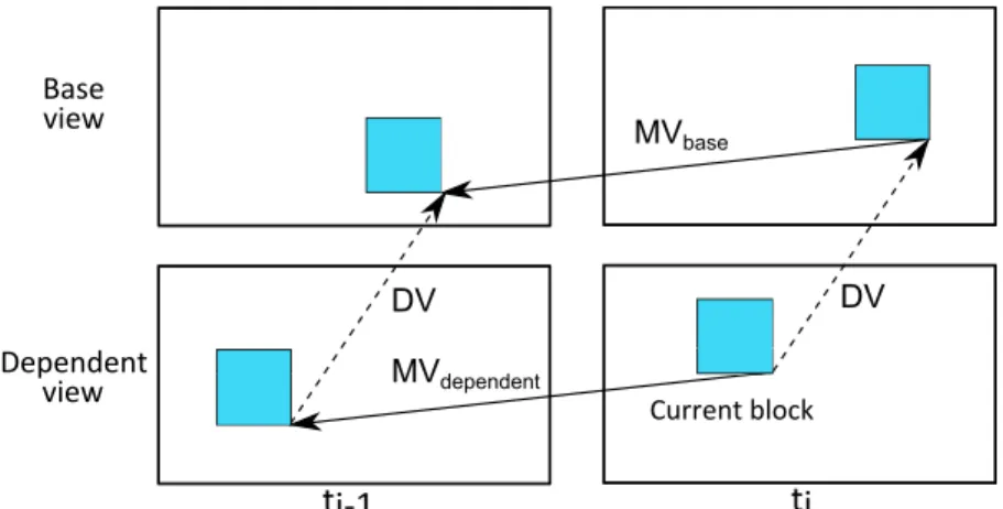
IVMP (An et al. 2012, Zhang et al. 2014) is a method that provides im-provement in coding efficiency of the dependent views. The basic concept of IVMP in 3D-HEVC is to derive the already coded motion parameter from the base view to be used in the dependent views. The reason behind this MV inheritance is that MVs in two different views are often correlated as shown in figure 1.12. Current block DV MVdependent Base ti-1 ti view Dependent view MVbase DV
Figure 1.12 – Correlation between motion vectors in base view and in dependent view. More precisely, when coding a current PU in a dependent view, a DV is first derived. By adding the DV to the middle position of the current PU, a reference sample location is obtained. The block in the already coded picture in base view that covers the sample location is used as the reference block. If this reference block is encoded using MCP, the associated MV can be inherited for the current PU in the current dependent view. Since that MV is not signaled in the bit stream, saving in signaling overhead is made.
1.3.4 Sub-PU Inter-View Motion Prediction (SP-IVMP)
SP-IVMP (An et al. 2013) is an improvement of IVMP and is thus a method to encode dependent views by inheriting motion parameters from the base view. In IVMP depicted in figure 1.12, the corresponding area in the base view pointed by the DV may have several different MVs (e.g. multiple objects inside the area); however, only the MV in the middle
Chapter 1. Video coding and HEVC standard
position of the area is inherited for the current PU in the dependent view. To improve this point, SP-IVMP proposes to split current PU in multiple smaller sub-PUs and to inherit motion parameters on sub-PU level.
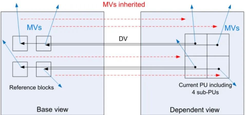
More precisely, as illustrated in figure 1.13, the current PU to be en-coded in a dependent view is divided into multiple sub-PUs of smaller size. For each sub-PU, a DV is added to the middle position pointing to a reference sample block in the base view. For each of those reference blocks, if it is coded using MCP, i.e. Inter mode, the associated MV is inherited for the corresponding sub-PU in the dependent view. Eventually, the motion parameter of the current PU is composed of multiple MVs corresponding to inner sub-PUs, all of them derived from the base view.
MVs inherited
Base view Dependent view
DV
Current PU including 4 sub-PUs Reference blocks
MVs MVs
Figure 1.13 – Inheritance of MVs on sub-PU level from base view to dependent view in SP-IVMP .
By providing finer granularity for the MVs derivation process, SP-IVMP yields significant improvement in bitrate savings compared to SP-IVMP method.
1.3.5 Advanced Residual Prediction (ARP)
ARP technique (Li et al. 2013) aims to further improve the coding efficiency of inter-view residual prediction, which predicts the residual of current block in the dependent views using the residual of its refer-ence block pointed by the DV in the base view. The residual predictor is produced by aligning the motion information at the dependent view for motion compensation in the base view.
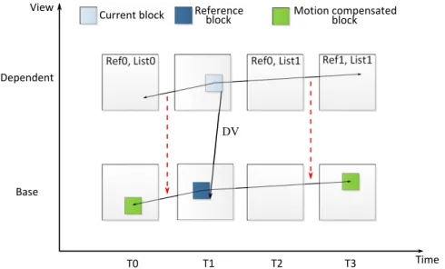
Figure 1.14 illustrates in more detail the ARP mechanism. Let us suppose that we are encoding the current block in a dependent view. After having its motion parameters (which point to pictures Ref0 of the reference picture listL0 and Ref1 of L1), instead of computing directly its residual by applying motion compensation in the dependent view, a residual predictor is computed by referring to the base view: motion of the current block in the dependent view is applied to a reference block pointed by the DV in the base view (red arrows indicate the inheritance of motion parameters from the dependent view to the base view) in order to generate the residual (between the green block and the blue block) in the base view to be used as the residual predictor.
1.4. Video coding techniques exploiting a complex decoder
The reason behind this motion inheritance is to ensure a high cor-relation between residuals of the two views. Indeed, since the residual predictor in the base view and the residual to be predicted in the depen-dent view belong to the same object thanks to the motion inheritance, the prediction performance is improved.
View
Time Dependent
Base
T0 T1 T2 T3
Current block Motion compensated
DV Reference
block block
Figure 1.14 – Inheritance of MVs (red arrows) to compute residual predictor in Advanced Residual Prediction.
When ARP is enabled for one block, the difference between the current residual and the residual predictor is signaled. With the consideration of both temporal motion and disparity information, the residual predictor is derived more accurately. Moreover, adaptive weighting factors are applied on the residual signal to compensate the quality difference between views so that the prediction error is further reduced.
1.4
Video coding techniques exploiting a complex
de-coder
Up until now, there are interesting coding techniques which stand out from conventional approaches by proposing different frameworks that re-quire significant modification at the decoder side. For better understand-ing, we will briefly explain the evolution of the decoder, from the most simple form that only reads data from the bit stream to complex struc-tures able to simulate the encoder in order to make a decision.
1.4.1 Basic decoder to a more complex decoder with joint computation
In classic coding schemes, for each block, the encoder performs the R-D competition of all coding modes and transmits the best encoding op-tion to the decoder. The latter then simply reads the encoding informaop-tion in the bit stream and decodes a block accordingly. All the computation is concentrated at the encoder while the decoder is very light. The decoder can be considered in this case as passive decoder. A video codec scheme using this type of decoder is illustrated in figure 1.15, where all coding
Chapter 1. Video coding and HEVC standard
parameters, such as coding modes param and motion information −mv,→
must be transmitted in the bit stream to the decoder.
Pre-processing Post-processing Source Destination Bit stream Passive decoder Encoder param mv
Figure 1.15 – Video coding scheme with passive decoder.
Various studies have emerged recently with the objective to further exploit the decoder by providing it with some processing ability. Joint computation in both encoder and decoder becomes possible, allowing some information to be retrieved in the decoder side without being signaled in the bit stream, reducing eventually the signaling overhead. Notable examples include approaches based on "Template Matching", a process that exploits the causal surrounding area of a block to derive motion parameters without signaling. This principle applied in Inter (Sugimoto et al. 2004, Kamp et al. 2008; 2009) proposes motion estimation that is jointly performed in both the encoder and the decoder. Resulting MVs are not transmitted, saving thus the signaling cost. Other variants can be applied in Intra (Tan et al. 2006) where the current block takes as predictor a block located in the reconstructed area of the current frame. In both cases, without receiving the MVs from the encoder, this type of decoder, called active decoder, can still retrieve those MVs by itself by performing motion estimation process similarly as in the encoder.
Figure 1.16 shows the modified codec scheme using an active decoder that incorporates some computation ability such as conducting the tem-plate matching process. Comparing with figure 1.15, we observe that there is no need to transmit the motion data−mv in the bit stream to the decoder→
because the decoder can conduct the same template matching process as in the encoder side in order to compute−mv by itself.→
Pre-processing Post-processing Source Destination Bit stream Active decoder Encoder param mv
Figure 1.16 – Video coding scheme with active decoder able to perform Template Match-ing process.
1.4.2 Complex decoder with R-D competition
In (Thiesse 2012), a novel approach is proposed to further exploit the processing ability of the decoder. Not only simple computation processes such as template matching can be conducted as previously mentioned, the decoder is also given the ability to simulate the encoder by conducting the