RESEARCH OUTPUTS / RÉSULTATS DE RECHERCHE
Author(s) - Auteur(s) :
Publication date - Date de publication :
Permanent link - Permalien :
Rights / License - Licence de droit d’auteur :
Bibliothèque Universitaire Moretus Plantin
Institutional Repository - Research Portal
Dépôt Institutionnel - Portail de la Recherche
researchportal.unamur.be
University of Namur
A two-in-one superhydrophobic and anti-reflective nanodevice in the grey cicada
Cicada orni (Hemiptera)
Dellieu, Louis; Sarrazin, Michaël; Simonis, Priscilla; Deparis, Olivier; Vigneron, Jean Pol
Published in:Journal of Applied Physics
DOI:
10.1063/1.4889849
Publication date:
2014
Document Version
Peer reviewed version
Link to publication
Citation for pulished version (HARVARD):
Dellieu, L, Sarrazin, M, Simonis, P, Deparis, O & Vigneron, JP 2014, 'A two-in-one superhydrophobic and anti-reflective nanodevice in the grey cicada Cicada orni (Hemiptera)', Journal of Applied Physics, vol. 116, no. 2, 024701. https://doi.org/10.1063/1.4889849
General rights
Copyright and moral rights for the publications made accessible in the public portal are retained by the authors and/or other copyright owners and it is a condition of accessing publications that users recognise and abide by the legal requirements associated with these rights. • Users may download and print one copy of any publication from the public portal for the purpose of private study or research. • You may not further distribute the material or use it for any profit-making activity or commercial gain
• You may freely distribute the URL identifying the publication in the public portal ?
Take down policy
If you believe that this document breaches copyright please contact us providing details, and we will remove access to the work immediately and investigate your claim.
arXiv:1406.7436v2 [physics.bio-ph] 11 Jul 2014
cicada Cicada orni (Hemiptera)
Louis Dellieu,1,a) Micha¨el Sarrazin,1,b) Priscilla Simonis,1
Olivier Deparis,1
and Jean Pol Vigneron1,c)
1Research Center in Physics of Matter and Radiation (PMR), Department of Physics, University of Namur (FUNDP),
61 rue de Bruxelles, B-5000 Namur, Belgium
Two separated levels of functionality are identified in the nanostructure which covers the wings of the grey cicada Cicada orni (Hemiptera). The upper level is responsible for superhydrophobic character of the wing while the lower level enhances its anti-reflective behavior. Extensive wetting experiments with various chemical species and optical measurements were performed in order to assess the bi-functionality. Scanning electron microscopy imaging was used to identify the nanostructure morphology. Numerical optical simulations and analytical wetting models were used to prove the roles of both levels of the nanostructure. In addition, the complex refractive index of the chitinous material of the wing was determined from measurements.
PACS numbers: 87.19.-j, 42.79.Wc, 68.08.Bc
I. INTRODUCTION
For a long time, anti-reflective properties have a major importance in the development of optical devices. For instance, anti-reflective coatings are required when de-signing telescopes, camera lenses, or glass windows. Such coatings allow e.g. avoiding undesirable reflections in op-tical imaging1. Moreover, since anti-reflective coatings
are wavelength-dependent, they can be used to reject ef-ficiently unwanted radiation, for instance to enhance ul-traviolet light protection in sunglasses1. In another
con-text, superhydrophobicity is a key property for numer-ous industrial applications2. Indeed, superhydrophobic
surfaces can exhibit self-cleaning properties: since wa-ter droplets cannot stick on such a surface, the rolling drops clear the surface from any impurities3. As a
mat-ter of fact, an optical device that could combine both anti-reflective and superhydrophobic properties is highly interesting4.
Anti-reflection is well known in biological organ-isms: e.g. nanostructures such as nipple arrays act as an adaptative refractive index layer in moth eyes for instance5,6. On the other hand, superhydrophobicity
is also well-known in many plants7–14, for instance in lotus11,12,15,16. Hydrophobic properties and
antireflect-ing nanostructures of cicada wantireflect-ings have been studied in-dependently in previous works17–22. Although the
func-tion as well as the physics of nipple arrays is well docu-mented from the point of view of either antireflection18or
hydrophobicity19–22, the understanding of the role of the
geometry in the interplay between optical and wetting properties deserves further investigations. Indeed, the combined aspect of wetting/hydrophobic/anti-reflective properties has not yet been considered as such, strictly speaking. Hereafter, thanks to extensive modeling and
a)Electronic mail: louis.dellieu@unamur.be b)Electronic mail: michael.sarrazin@unamur.be
c)Our friend and colleague Prof. Jean Pol Vigneron accidentally
died on June 24, 2013, during the early writing of this article.
measurements, we show that the grey cicada combines both hydrophobic and anti-reflective properties in an en-tangled two-level nanostructure. Especially, wetting and hydrophobic properties are studied for a wide range of liquids with various surface tensions. In addition, we de-termine the complex refractive index of the wing, which is useful and often needed as reference in biophotonics simulations.
II. MORPHOLOGY AND STRUCTURAL MODEL OF THE WING MEMBRANE
The grey cicada (Fig. 1) is one of the most frequent cicada species in the south of France. The studied spec-imen was captured at Al´es in the C´evennes region. The grey cicada is about 40 mm long and has a 75 mm wing span. In order to investigate the nanostructure of the wing, scanning electron microscopy (SEM) imaging was performed with Jeol 7500 F scanning electron micro-scope.
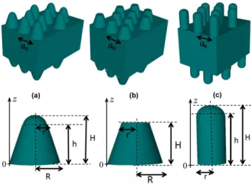
Both sides of the wing are covered by a hexagonal nip-ple array (Fig. 2(a)). Each protuberance is a truncated cone, with a hemispherical top (Fig. 2(b)). Protuber-ances lay on a 2.7 µm-thick slab. This type of protuber-ance is often encountered in compound eyes or corrugated wings of insects5,23–25. According to SEM pictures, the
FIG. 1. (Color online). The grey cicada Cicada orni (Hemiptera).
2
FIG. 2. Scanning electron microscopy images of the cicada wing (same scale for both figures). a: Typical hexagonal nip-ple array is clearly observed. b: Protuberances consist of conic-like tips with a hemispherical top.
typical dimensions and geometry of the different parts of the structure can be estimated on average (see Fig. 3(a)). The truncated cone has a circular base of radius R ≈ 85 nm, and a height h ≈ 160 nm. The top hemi-sphere has a radius r ≈ 40 nm. The total height (cone + hemisphere) is therefore H ≈ 200 nm. The average hexagonal lattice parameter is a0 ≈ 173 nm. We fairly
assume that the disorder in the biological structure, i.e. weak deviations with respect to perfect lattice, does not significantly affect the main conclusions of the present study26.
III. OPTICAL PROPERTIES
In the following, we highlight the anti-reflective prop-erties of the cicada wing through scattering and transmis-sion measurements. Based on models of the wing struc-ture, simulations were performed in order to study the role of the morphology on the optical properties.
A. Experimental results
The diffusive and polarizing characters of the wing were investigated at incidence angles i of 0◦, 15◦and 30◦
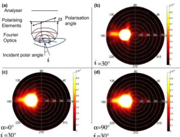
using scatterometry in transmittance mode (ELDIM EZ-contrast scatterometer). This scatterometer uses Fourier lenses to record the bidirectional transmittance or re-flectance distribution function (BTDF or BRDF) of the sample (Fig. 4(a)) at visible wavelengths. In order to detect possible polarization of the emerging light, a po-larizer was placed as analyzer as shown in Fig. 4(a). In a first step (calibration), at each incidence angle, the BTDF of the incident beam alone (without wing and po-lariser) was measured, showing purely specular transmit-tance as expected (Fig. 4(b)). In a second step, the wing was inserted and the polarizer was positioned perpendic-ular (α = 90◦) to the wing longitudinal axis and then
parallel to it (α = 0◦). BTDFs of the wing for both
analyzed polarizations were recorded. At each incidence angle i, both BTDF maps were compared to the BTDF map of the incident beam alone. As polarization effects
should be observed preferably at large incidence angles, the results in Fig. 4(c) and 4(d) are presented for the incidence angle i of 30 degrees (and a wavelength λ ∼= 510 nm in the middle of visible range). Accordingly, nei-ther diffusive effects nor polarizing effects of the wing could be detected (Fig. 4(c) and 4(d)). Results (not shown) were identical for the other wavelengths in the visible spectrum (according to the characteristics of our scatterometer). Since the wing exhibited a very low dif-fusive character and in order to optimize the signal to noise ratio, transmission properties are mainly empha-sized hereafter by contrast with reflection properties.
Measurement of the wing optical properties spec-trum were performed at normal incidence using a dou-ble beam spectrophotometer (Perkin Elmer Lambda 750 S UV/VIS/NIR) and an integrating sphere. In Fig. 5(a), reflection spectrum is shown. Since reflection is very weak, measurement was made with the wing on a black substrate (Certified Reflectance Standard SRS-02-020 Labsphere with a reflectance factor of 2% be-tween 250 and 2500 nm). The measured reflection Rm
had to corrected since Rm was fairly approximated by
Rm ≈ Rw+ Rbg · Tw2 (see insert in Fig. 5(a)) where
Rw was the expected wing reflection, Rbg was the black
substrate reflection (which was measured independently, not shown), and Tw was the free-standing wing
trans-mission which is measured independently (see hereafter). In Fig. 5(a), the blue dashed curve is Rm whereas the
black solid curve is Rw which is deduced from the above
expression. This correction confirms that reflection val-ues are weak in accordance with previous results18, and
must be derived carefully. In addition, it is well-known that spectroscopic measurements are impacted by instru-mental noise for low transmittance or reflectance levels. As a consequence, it is more relevant to compare high-level transmittance measurements with numerical
mod-FIG. 3. (Color online). Various geometrical models studied. a: Model of the wing structure, b: Model used to study the influence of top hemisphere on transmission, c: Model used to study the influence of truncated cone on transmission.
els, rather than low-level reflectance measurements. Let us now consider transmission measurements. They were carried out on free-standing wings i.e without sub-strate. The black curve in Fig. 5(b) indicates an almost perfect transmission in the visible range although it ap-pears to be weaker on the blue side than on the red side of the spectrum. This means that almost 100% of the light passes through the free-standing wing without being ab-sorbed or reflected. The transmission exhibits a large drop below 350 nm, due to a strong intrinsic absorption in the ultra-violet range. Note that in Fig. 5(a) we found that reflection does not fade away at these wavelengths. Using the absorption coefficient calculated from reflec-tion and transmission at each wavelength, the spectrum of the imaginary part of the complex refractive index was deduced from the Beer-Lambert law27 as shown in Fig. 5(c).
In order to reveal the effect of the nipple array on the optical properties, the wing was covered with a calibrated refractive-index oil. Indeed, provided that the oil refrac-tive index matches the refracrefrac-tive index of the protuber-ances, the oil filling the air cavities and the material can be regarded as a single planar layer. Here, a decrease of transmission was noted using a calibrated commer-cial oil with a real part of refractive index equal to 1.56 (see blue dashed curve on Fig. 5(c)). This oil is cer-tified by the manufacturer Cargille Labs (also verified by us) with a negligible dispersion on the visible range and a weak dispersion in the ultraviolet domain. Such a refractive-index value is consistent with that of chitin28.
As a result, in the following, we will assume that the cicada wing is made of a chitin-like compound with an average refractive index of 1.56. On Fig. 5(b), the blue dashed curve (transmission spectrum of wing immersed in index matching oil) shows a transmission drop of 6% in the visible range and spectral changes in the UV range. One can then conclude that the nipple array increases the transmission by 6%, improving the transparency of the wing. These results are in agreement with those ob-tained by other authors18. Since UV absorption of the
chitin material was determined, the absorption coefficient of the wing (extrapolated from experimental measure-ment) (Fig. 5(c)) will be used in the following numerical simulations.
B. Theoretical analysis
On the basis of morphological data, we described the wing as a homogeneous slab with, on both side, a hexag-onal array of truncated cones with top hemisphere (Fig. 3(a)). For the sake of simplicity, we assumed that the wing was made of chitin only. The real part of the re-fractive index was taken equal to 1.56 and was assumed to be constant all over the simulation spectral range whereas the absorption coefficient was taken wavelength-dependent according to data shown in Fig. 5(c). Simula-tions of the optical properties were carried out from the
FIG. 4. (Color online). Bidirectional Transmittance Distri-bution Functions (BTDF) (in watt/m2/sr/nm). Results are shown for polar angles ranging from 0◦to 80◦and azimuthal
angles in ranging from 0◦ to 360◦. The wavelength is λ =
509.48 nm. a: Principle of the scatterometer. b: BTDF of the incident beam at an angle of incidence i = 30◦. c,d:
BTDF of the cicada wing at i = 30◦and for two orthogonal
analyzing polarizer orientations, 0◦(panel (c)) and 90◦(panel
(d)).
near UV to the near infrared (200 to 800 nm) by using a transfer matrix code26.
Since the nipple array has subwavelength dimensions, the corrugated layer can be considered as a continuous effective material with a graded-index along its thick-ness. More specifically, the effective dielectric constant can then be defined by5:
ε(z) = εair+ (εchitin− εair)f (z), (1)
where εair is the dielectric constant of air (εair = 1),
εchitinis the dielectric constant of chitin and f (z) is filling
factor given by:
f (z) = πr 2(z) S , (2) with S = a 2 0 √ 3
2 and r(z) the radius of the circular
sec-tion of a nipple at coordinate z. While light propagasec-tion in corrugated layers is computed thanks to the transfer matrix code, light propagation in the homogeneous thick slab is calculated using an analytical expression based on Fresnel equations in which phases are set to zero in order to mimic optical incoherence. Indeed, structural imper-fections in the slab, which is a thick biological layer, tend to break constructive light wave interferences. Finally, although we choose to focus on transmission for the rea-sons we exposed previously, simulations of reflection are also performed to corroborate our results.
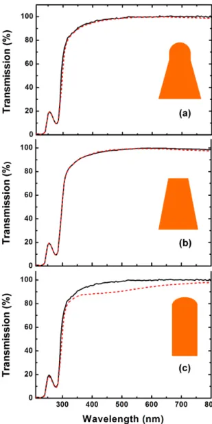
Simulation results for transmission are shown in Fig. 6(a). The black curve corresponds to the measured
trans-4
FIG. 5. (Color online). a: Measured wing reflection spectrum at normal incidence (blue dashed curve) and corrected mea-surement (black solid curve). Insert: Correction procedure. b: Measured wing transmission spectrum. Measurements on the actual free-standing wing (black curve) and the wing im-mersed in index matching oil (blue dashed curve). c: Imag-inary part of the optical index of the cicada wing obtained from reflection/transmission measurements.
mission whereas the red curve corresponds to the simu-lated transmission: The two curves match very well. This result is valid whatever the polarization state is. In or-der to discriminate the role of the truncated cone and the role of the top hemisphere, two alternative wing models were considered. We first considered a truncated cone without the hemisphere on top (see Fig. 3(b)). Fig. 6(b) shows the simulated spectrum (red curve) and the mea-sured spectrum (black curve). Both transmission spectra match quite well, showing that the hemisphere does not actually contribute to the transparency of the wing. In
FIG. 6. (Color online). a: Measurement (black solid curve) and theoretical simulation (red dashed curve) on the actual wing model. b: Measurement (black solid curve) vs. theo-retical simulation on the wing model without hemispheres on top (red dashed curve). c: Measurement (black solid curve) vs. theoretical simulation on the wing model with cylinders instead of truncated cones (red dashed curve).
a second simulation, we considered a cylinder (instead of a cone) (see Fig. 3 (c)) with a hemisphere on top. The result is shown in Fig. 6(c). The simulated transmission (red curve) is significantly lower than the measured one (black curve). Together with the previous simulation, this result shows that the truncated cone is required to get transparency in the visible range. This can be eas-ily understood since the truncated cone avoids a sudden change in the refractive index when light impinges on the slab. Indeed, considering Eq. (1), the truncated cone cre-ates a gradient of refractive index which acts as an optical impedance adaptation layer.
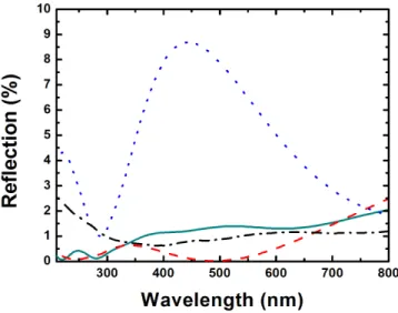
FIG. 7. (Color online). Theoretical simulation (red dashed curve) of the reflection on the full wing model (Fig. 3 (a)). This curve can be compared with the simulated reflections for the wing model without hemispheres on top (cyan solid curve) or with cylinders instead of truncated cones (blue short-dashed curve). The black dash-dotted curve is the mea-sured reflection.
Let us now consider the simulated reflection. Our re-sults are summarized in Fig. 7. The measured (black dash-dotted curve) and simulated (red dashed curve) re-flections exhibit comparable values about 1%. Never-theless, we note that spectra of both reflections do not perfectly match. As explained previously, this can be explained by the lack of accuracy when measuring weak reflections. We also present the simulated reflection for the wing model without hemispheres (cyan solid curve). As for the transmission (Fig. 6(b)), there is negligible difference (less than 2%) with the full wing model (Fig. 3(a)). Now, by contrast, if we consider the model with cylinders instead of truncated cones, we see that the re-flection increases by a factor 10. This corroborates qual-itatively our results obtained with the transmission (Fig. 6(c)). In addition, we note the strong oscillations of the simulated reflection, since the array of cylinders acts as a thin effective homogeneous slab where interferences can occur.
IV. WETTING PROPERTIES
In this section, contact angle measurements are re-ported and wettability regimes are investigated. Analyt-ical models are used to describe the superhydrophobicity of the wing.
FIG. 8. (Color online). Wetting measurement on wing of Cicada orni, the contact angle is 146◦.
A. Experimental results
A surface can be classified as superhydrophobic if the contact angle of a water droplet on the surface is higher than 150◦. If the contact angle lies between 90◦and 150◦,
the surface is only hydrophobic and it is hydrophilic if the contact angle lies between 0◦and 90◦. In the present
case, the contact angle of a water droplet on the wing sur-face is measured to be 146◦(Fig. 8). As a consequence,
the wing of Cicada orni is almost superhydrophobic. Ac-cording to previous works related to the link between nanostructure and superhydrophobicity20,23,29–31, we can
fairly assess that the nipple array covering the wing sur-face is responsible for its hydrophobic properties (see Fig. 9). Indeed, without the nanostructure, the water droplet would probably spread on the surface since the contact angle of water on a flat chitin surface is about 105◦32.
For a better understanding of the wing hydrophobic-ity, it is relevant to measure the wetting properties for various liquids with different surface tensions. For this purpose, we used ethanol-water solutions with different mass percentages of ethanol (from 0% to 100%), but also a 6.0 M sodium chloride aqueous solution and mercury.
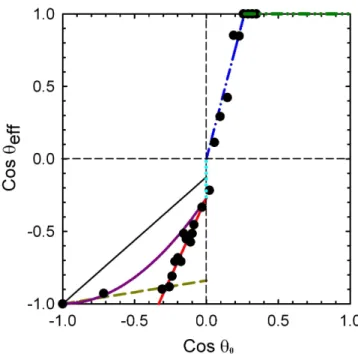
The effective contact angle θef f for each liquid on the
wing (the nanostructured surface) was measured, and cos θef f was plotted against cos θ0, where θ is the
con-tact angle on a flat chitin surface (Fig. 10 ; black dots correspond to measured values). Since the liquid-gas sur-face tension γLGof the used liquids are known33–35, and
since the solid-gas surface tension γSG of chitinous
ma-terial can be calculated (see further), it is possible to calculate the contact angle θ0for a given liquid on a flat
chitinous surface, using the Young equation3:
γSG = γSL+ γLGcos θ0. (3)
ap-6
FIG. 9. (Color online). Wetting models under consideration. a: Wetting model from the full cicada’s wing description. b: Wetting model without hemispheric top. The angle θ0
corre-sponds to the Young’s contact angle for a flat chitin surface.
proximated by3: γSL≈ γSG+ γLG− 2√γSGγLG, (4) we then get cos θ0= 2 rγ SG γLG− 1 (5) from Eqs (3) and (4). Since γLG of water is known, as
well as the contact angle of a water droplet on flat chiti-nous surface (θ0 = 105◦)32, we deduce from (3) γSG ≈
9.9 × 10⁻³N·m−1. In Fig. 10, gold and red lines denote
the linear asymptotic trends in data when cos θef f < 0,
i.e. when the wing is not wet. By contrast, the blue line denotes the behavior of the wet wing (cos θef f > 0), i.e.
the hydrophilic regime. The horizontal green line cor-responds to the process of hemiwicking36,37. According
to these results, we observe a transition from a superhy-drophobic regime to a hydrophilic regime.
FIG. 10. (Color online). Effective contact angle θef f (nanos-tructured surface) as a function of the contact angle θ0 on
a flat surface. The black dots are the experimental results. The blue (dash-dotted) straight line is plotted from Eq. (9), the purple (solid) curve is from Eq. (7). Gold (dashed) and red (solid) straight lines show trends by contrast to the ideal model. Light blue (dotted) vertical straight line corresponds to the hydrophobic/wetting transition. The green (dash-dot-dotted) straight line corresponds to the process of hemiwick-ing. Black solid line is plotted from Eq. (8).
B. Theoretical analysis
Models of wetting processes are used hereafter in or-der to predict the contact angle of a water droplet on the wing. Specifically, they are used to describe the su-perhydrophobic, hydrophobic or hydrophilic behavior of the wing. Two theoretical models are considered : the Cassie-Baxter model for the hydrophobicity regime and Wenzel model for the hydrophilic regime.
The Cassie-Baxter (CB) model38allows to describe the
wetting process on superhydrophobic and hydrophobic surfaces according to their roughness (i.e. nipple array). For a surface made of two different materials with differ-ent coverage areas, the contact angle θCB of the
hetero-geneous surface is given by:
cos θCB= f1cos θ1+ f2cos θ2. (6)
where f1and f2are the fractional areas of each material
(f1 + f2 ≥ 1), and θ1 and θ2 are the contact angles,
respectively.
Using the nipple geometry previously described, we consider the wetting model shown on Fig. 9(a). The contact angle in the present case can be written as39:
cos θCB = nπr2(1 + cos θ0)2− 1, (7)
where n is the number of hemispheres per unit area for a hexagonal array, r is the radius of the hemisphere, and θ0
is the contact angle of a droplet deposited on flat chitin. This well-known equation, can be simply derived from Eq. (6) by assuming that θ1= θ and θ2= 180◦. Indeed,
θ2 is the contact angle between a droplet and air, which
is assumed to be 180◦. Fractional areas can be easily
derived from trivial geometrical considerations. On Fig. 10, Eq. (7) is plotted as the purple curve with θCB =
θef f, using geometrical parameters mentioned in section
II and measured from SEM pictures. Gold and red lines show wetting trends experimentally observed by contrast to the theoretical model40. Though the theoretical curve
and the experimental data do not perfectly match, the trends are the same. Differences are likely due to the fact that the water/air interface (see Fig. 9(a)) is not truly a planar one, modifying then the conditions for which the Gibbs energy is minimized3. Nevertheless, more accurate
modeling is a complex task far beyond the scope of the present work41.
We note that, using Eq. (7), we find a theoretical con-tact angle of 151◦ for water by contrast with the
mea-sured value of 146◦, i.e there is less than 4% difference
between theory and experiment.
In order to clearly demonstrate the essential role of the hemispherical top, we investigated the wetting properties of the conical base structure without the top hemisphere (Fig. 9(b)). In this case, the Cassie-Baxter contact angle is simply given by:
cos θCB= f cos θ0+ (f − 1) , (8)
with f = πr2/S and S = a20
√
3/2. The linear depen-dence, which is plotted in Fig. 10 as a black solid line, leads to much less satisfactory agreement with data, as compared with the quadratic dependence (purple curve) pertaining to the hemispherical top, i.e. Eq. (7). In-deed, for water (θ0 = 105◦), a theoretical contact angle
of θCB = 111◦is predicted by Eq. (8), whereas a value of
151◦ was determined previously by Eq. (7). Therefore,
only the model including the hemispherical top is able to account for the superhydrophobicity of the wing.
The hydrophilic behavior of a corrugated surface, on the other hand, can be described thanks to the Wenzel (W) model42. In this case, the contact angle is given by: cos θW = rocos θ0, (9)
where rois the roughness factor which is in our case given
by: ro= 2πr 2+ πG(R + r) + a2 0 √ 3/2 − πR2 S , (10) with S = a2 0 √
3/2, r the radius of the hemisphere, R the radius of the base of the cone, G the length of the cone (≈ 166 nm) and a0the spatial period. Equation (8)
is a linear relation between the effective contact angle and the contact angle on a flat surface made of the same material. On Fig. 10, Eq. (9) is plotted as blue curve with θW = θef f, using geometrical parameters mentioned
in section II and measured from SEM pictures. Here, the model matches very well with the experimental data.
We emphasize the fact that the wetting models under-line the role of the top hemisphere in the wetting phe-nomena, and especially in the hydrophobic behavior of the cicada wings. In the wetting regime, the whole struc-ture geometry must be considered to explain the wetting.
V. SUMMARY AND CONCLUSION
While it is known that cicada wings possess both hydrophobic17–19 and anti-reflective properties5,6, in the
present work we underlined the two-in-one character of the geometrical features leading both to the optical and wetting properties of the cicada. From scanning electron microscopy, it was shown that the cicada wing consisted of a thick chitinous layer whose each side was covered by a nanostructured device in the form of an hexagonal nip-ple array. Each nipnip-ple was modeled by a truncated cone topped by an hemisphere. We performed an original wet-ting experiment with various chemical species as well as comprehensive optical measurements providing the com-plex refractive index of the chitinous wing. From optical simulations and using an analytical wetting model, we demonstrated the character of the two functional levels of the nipple array. We concluded that the hemisphere on the top of the nipple was useful for the superhydropho-bic character of the cicada wing. This half-sphere played no optical role. By contrast, the truncated cone played no significant role in the hydrophobic behavior while it was found to be fundamental for ensuring transparency of the cicada wing (anti-reflection). Therefore, the nipple array nanostructure in the grey cicada can be considered as a two-in-one device: a hemisphere top which allows a strong water repellency and a truncated cone which ensures anti-reflective properties.
ACKNOWLEDGMENTS
The authors thank Corry Charlier, Jean-Fran¸cois Colomer, Quentin Spillier and Micha¨el Lobet for their technical support and advice. L.D. is supported by the Belgian Fund for Industrial and Agricultural Research (FRIA). M.S. is supported by the Cleanoptic project (development of super-hydrophobic anti-reflective coat-ings for solar glass panels/convention No.1117317) of the Greenomat program of the Wallonia Region (Belgium).
8
2L. Yan, K. Wang, J. Wu, L. Ye, Colloids and Surfaces :
Physic-ochem. Eng. Aspects 296, 123 (2007).
3H.-J. Butt, K. Graf, M. Kappl, Physics and Chemistry of
Inter-faces(Wiley-VCH, 2005).
4X. Li, J. He, W. Liu, Materials Research Bulletin 48, 2522(2013). 5D.G. Stavenga, S. Foletti, G. Palasantzas, K. Arikawa, Proc. R.
Soc. B 273, 661 (2006).
6C.G. Bernhard, Endeavour 26, 79 (1967).
7L. Feng, Y.A. Zhang, J.M. Xi, Y. Zhu, N. Wang, F. Xia, L. Jiang,
Langmuir 24, 4114 (2008).
8L. Feng, Y.A Zhang, M.Z Li, J.M. Zheng, W.Z. Shen, L. Jiang,
Langmuir 26, 14885 (2010).
9B. Bhushan, E.K. Her, Langmuir 26, 8207 (2010).
10K. Koch, W. Barthlott, Phil. Trans. R. Soc. A 367, 1487 (2009). 11W. Barthlott, C. Neinhuis, Planta 202, 1 (1997).
12W. Barthlott, C. Neinhuis, Ann. Bot 79, 667 (1997). 13P. Ball, Nature 400, 507 (1999).
14L. Feng, S.H. Li, Y.S. Li, H.J. Li, L.J. Zhang, J. Zhai, Y.L. Song,
B.Q. Liu, L. Jiang, D.B. Zhu, Adv. Mater. 14, 1857 (2002).
15A. Solga, Z. Cerman, B. F. Striffler, M. Spaeth, and W. Barthlott,
Bioinspir. Biomim. 2, S126 (2007).
16N.M. Pugno, The Nanomechanics in Italy (Research Signpost,
2007).
17G. Xie, G. Zhang, F. Lin, J. Zhang, Z. Liu, S. Mu,
Nanotechnol-ogy 19, 095605 (2008).
18M. Sun, A. Liang, Y. Zheng, G.S. Watson, J.A. Watson, Bioinsp.
Biomim. 6, 026003 (2011).
19M. Sun, G.S. Watson, Y. Zheng, J.A. Watson, A. Liang, J. Exp.
Biol. 212, 3148 (2009).
20G.S. Watson, S. Myhra, B.W. Cribb, J.A. Watson, Biophys. J.
94, 3352 (2008).
21M. Sun, A. Liang, G.S. Watson, J.A. Watson, Y. Zheng, J. Ju,
L. Jiang, PLoS ONE 7 e35056 (2012).
22K.M. Wisdom, J.A. Watson, X. Qu, F. Liu, G.S. Watson, C.-H.
Chen, PNAS 110 7992 (2013).
23D. Byun, J. Hong, Saputra, J.H. Ko, Y.J. Lee, H.C. Park, B.
Byun, J.R. Lukes, J. Bionic Eng. 6, 63 (2009).
24O. Deparis, N. Khuzayim, A. Parker, J.P.Vigneron, Phys. Rev.
E 79, 041910 (2009).
25A. Yoshida, Forma 17, 75 (2002).
26J.P. Vigneron, V. Lousse, Proc SPIE 6128, 61281G (2006). 27A. Beer, Ann. Phys. (Berlin) 162, 78 (1852).
28A. R. Parker, R. C. McPhedran, D. R. McKenzie, L. C. Botten,
N. A. Nicorovici, Nature 409, 36 (2001).
29S.N. Gorb, A.Kesel, J.Berger, Arthropod Struct. Dev. 29, 129
(2000).
30T. Wagner, C. Neinhuis, W. Barthlott, Acta Zool-Stockholm 77,
213(1996).
31Y. Zheng, X. Gao, L. Jiang, Soft Matter 3, 178 (2007). 32M.W. Holdgate, J. Exp. Biol. 32, 591 (1955).
33G. Vazquez, E. Alvarez, J. Navaza, J. Chem. Eng. Data 40, 611
(1995).
34M. Wigglesworth, T. Wood, Management of Chemical and
Bio-logical Samples for Screening Applications(Wiley-VCH, 2012).
35A.W. Adamson, A.P. Gast, Physical Chemistry of Surfaces (John
Wiley and Sons Inc., 1997).
36D. Qu´er´e, Physica A 313, 32 (2002).
37C.W. Extrand, S.I. Moon, P. Hall, D. Schmidt, Langmuir 23,
8882 (2007).
38A.B.D. Cassie, Discuss. Faraday Soc. 3, 11 (1948).
39J. Bico, C. Marzolin, D. Qu´er´e, Europhys. Lett. 47, 220 (1999). 40T. Onda, S. Shibuichi, N. Satoh, K. Tsujii, Langmuir 12, 2125
(1996).
41T. Koishi, K. Yasuoka, S. Fujikawa, T. Ebisuzaki, X.C. Zeng,
PNAS 106, 8435 (2009).