RESEARCH OUTPUTS / RÉSULTATS DE RECHERCHE
Author(s) - Auteur(s) :
Publication date - Date de publication :
Permanent link - Permalien :
Rights / License - Licence de droit d’auteur :
Bibliothèque Universitaire Moretus Plantin
Institutional Repository - Research Portal
Dépôt Institutionnel - Portail de la Recherche
researchportal.unamur.be
University of Namur
Structural and quantitative analysis of stainless steel coatings deposited by
DC-magnetron sputtering in a reactive atmosphere
Terwagne, Guy; Hody, Hubert; Colaux, Julie
Published in:Surface and Coatings Technology
Publication date: 2003
Document Version Peer reviewed version
Link to publication
Citation for pulished version (HARVARD):
Terwagne, G, Hody, H & Colaux, J 2003, 'Structural and quantitative analysis of stainless steel coatings deposited by DC-magnetron sputtering in a reactive atmosphere', Surface and Coatings Technology, vol. 174-175, pp. 383-388.
General rights
Copyright and moral rights for the publications made accessible in the public portal are retained by the authors and/or other copyright owners and it is a condition of accessing publications that users recognise and abide by the legal requirements associated with these rights. • Users may download and print one copy of any publication from the public portal for the purpose of private study or research. • You may not further distribute the material or use it for any profit-making activity or commercial gain
• You may freely distribute the URL identifying the publication in the public portal ?
Take down policy
If you believe that this document breaches copyright please contact us providing details, and we will remove access to the work immediately and investigate your claim.
0257-8972/03/$- see front matter䊚 2003 Elsevier Science B.V. All rights reserved. doi:10.1016/S0257-8972(03)00594-2
Structural and quantitative analysis of stainless steel coatings deposited
by DC-magnetron sputtering in a reactive atmosphere
G. Terwagne*, H. Hody, J. Colaux
Laboratoire d’Analyses par Reactions Nucleaires, Facultes Universitaires Notre-Dame de la Paix, 61, rue de Bruxelles-B-5000 Namur, Belgium´ ´ ´
Abstract
Stainless steel coatings were deposited on low carbon steel and thin SiO substrates by DC-magnetron sputtering in a reactive2
atmosphere containing argon, nitrogen and hydrogen. The total mass flow of nitrogen was kept constant (8 sccm) for all depositions and the hydrogen mass flow was varied between 0 and 9 sccm while argon mass flow was chosen to obtain a total pressure of 0.28 Pa in the chamber. The elemental composition of coatings and the deposition rates were studied by Rutherford backscattering (RBS), by X-ray emission induced by charge particles (PIXE), by nuclear reactions (NRA) and by resonant nuclear reactions (RNRA). The hydrogen and nitrogen contents in the deposited layers are found to increase with increasing hydrogen mass flow and the deposition rates are decreased with decreasing of argon mass flow. The hydrogen depth profiles in the coatings show an accumulation of hydrogen located at the surface and the interface. A structural analysis by means of conversion electron Mossbauer spectroscopy¨ (CEMS) was also performed. The results indicate that some minor structural modifications were observed when the mass flow of hydrogen was increased.
䊚 2003 Elsevier Science B.V. All rights reserved.
Keywords: PVD; Magnetron sputtering; Stainless steel; Nitrogen; Hydrogen
1. Introduction
Austenitic stainless steels are well known for their corrosion resistant qualities but their poor wear resis-tance limits their performance. Nitriding of these steels can be performed by several techniques such as conven-tional ion implantation w1–4x, pulsed plasma nitriding
w5x and plasma immersion ion implantation (PI ) w6x.3 As long as the treatment temperature is kept below a critical value of approximately 450 8C, the wear resis-tance can be improved without compromising the cor-rosion performance. At these lower temperatures, nitrogen remains in solid solution, producing a phase that has been variously called ‘S-phase’ w7x, ‘expanded austenite’ w8x, or gNphase w3,4x.
Magnetron sputtering offers new possibilities and more flexibility for producing coatings on various sub-strates at low temperature. While coatings sputtered from austenitic stainless steel targets at low temperature usually form a ferritic bcc structure w9x, addition of nitrogen to the sputtering gas results in a nitrogen *Corresponding author. Tel.: 5478; fax: q32-81-72-5474.
E-mail address: [email protected](G. Terwagne).
supersaturated fcc phase with improved wear resistance and higher corrosion resistance w10–12x. These coatings, whose properties and structure are similar to the ‘S-phase’ produced by nitriding, can be produced by DC-magnetron sputtering using stainless steel targets.
The purpose of this paper is to study the influence of hydrogen on the growth of nitrided stainless steel coat-ings and to produce a more effective nitrogen phase. In a previous work, we have shown that the deposition rate of the nitrided stainless steel depends on nitrogen mass flow w13x. Typical deposition rate approximately 2.4=1015 at. cmy2 sy1 were observed for a DC-magnetron power of 100 W and nitrogen mass flow lower than 25% of the total sputter and reactive gases in the chamber. We can double the deposition rate if we double the DC-magnetron power, but it is also possible to increase the deposition rate when hydrogen is added to the reactive gas w14x. This investigation shows that some improvement in nitriding efficiency can be obtained when less than 10% of hydrogen is added to the reactive and sputter gases. Elemental composition analysis is realised by nuclear reaction analysis(NRA),
resonant nuclear reaction analysis(RNRA), X-ray emis-sion induced by charge particles(PIXE) and Rutherford
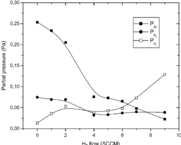
Fig. 1. Partial pressures of Ar, N and H as a function of hydrogen2 2
mass flow.
Table 1
Relative amount of Fe, Cr, Ni, N and H measured for different coatings
Coating Ar flow N flow2 H flow2 wFex wCrx wNix wNx wHx
number (sccm) (sccm) (sccm) (at.%) (at.%) (at.%) (at.%) (at.%)
1 28.0 8 0 46.5 10.0 4.5 28 8 2 28.0 8 1 46.5 10.0 4.5 28 8 3 26.0 8 2 47.5 10.0 4.5 30 5 4 18.8 8 3 48.0 10.5 4.5 30 7 5 17.1 8 4 46.5 9.5 4.0 31 7 6 16.2 8 5 46.5 9.5 4.0 31 7 7 12.5 8 6 46.5 9.5 4.0 31 7 8 9.7 8 7 46.5 9.5 4.0 32 8 9 4.2 8 9 42.5 7.5 3.0 32 15
Nitrogen flow is kept constant while hydrogen flow is increased. The argon flows have been set to keep constant the total pressure in the chamber.
backscattering spectroscopy (RBS), whereas structural analysis is performed by means of conversion electron Mossbauer spectroscopy¨ (CEMS).
2. Sample preparation
The coatings were deposited using an unbalanced DC-magnetron sputtering system placed in a small chamber of 0.05 m equipped with a 280 l3 ys
turbo-molecular pump which provides a base pressure of 10y5 Pa. A 50 mm diameter AISI-304L (composition
in wt.%-Fe:70%, Cr:18%, Ni:10% and Mn:2%) disk
target was placed just above the magnets with a good thermal contact to the holder in order to cool the magnetic material with water during deposition. The source to sample holder distance was 150 mm and a chimney was placed on the top of the target to prevent contamination of the whole chamber. A shutter was placed between the top of chimney and the sample holder in order to avoid deposition during target cleaning for 5 min before each deposition.
Two sets of substrates were used in this study: a. SiO disk2 (20 mm in diameter) of 200 mm thick to
measure the deposition rates and the elemental anal-ysis of the coatings,
b. Low carbon steel for the elemental and structural analysis.
The low carbon steel disk of diameter 20 mm and thickness 0.25 mm were mechanically polished with diamond paste (15 and 1 mm) and then with alumina powder (0.5 mm). The substrates were cleaned in an ultrasonic bath with pentane before loading into the chamber. Prior to each deposition, the substrates were etched for 2 min in order to remove oxide from the steel surface and to enhance coating adhesion.
Depositions were made at room temperature in the same conditions for both sets of substrates. The mag-netron power was set to 200 W during deposition and the voltage applied to the sputter target was approxi-mately y500 V. Although the substrate was heated by
electron and ion bombardment, the temperature was measured below 100 8C during deposition with a ther-mocouple placed at the rear of the specimen. The coatings were reactively deposited during 15 min with various AryN yH gas mixtures, which give various2 2 thicknesses, which can be related to the Ar flow (see below). The N flow in the sputter gas was kept constant2 at 8 sccm for all specimens, while the proportion of H2 was varied by changing the H flow rate, with compen-2 sating adjustment of the Ar flow rate, such that the total pressure remains constant in the chamber (Table 1).
These flows correspond to a total pressure of 0.28 Pa measured with a baratron gauge placed in the deposition chamber. The partial pressure of Ar, N , H and other2 2 residual gases were measured using a 7 mtorr Micropole Analyser with 1.2 amu resolution. Fig. 1 shows the partial pressure of Ar, N and H vs. H flow. It is2 2 2 clearly observed that the Ar partial pressure is drastically
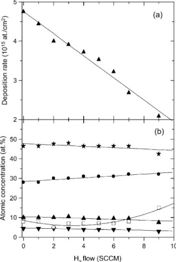
Fig. 2.(a) Deposition rates measured by RBS as a function of
hydro-gen flow;(b) atomic concentration of Fe (w), Cr (m) and Ni (%)
measured by PIXE, N(d) measured by NRA and H (h) measured
by RNRA vs. the hydrogen mass flow. The solid lines have been drawn as a guide for the eyes.
decreasing when the H flow is increasing. This effect2 will certainly affect the deposition rates(Section 3).
3. Coatings characterisation
3.1. Elemental analysis
Nuclear elemental analyses were performed at LARN with the 2 MV Tandetron ALTAIS accelerator¨ (‘Acce-´ lerateur´ Lineaire´ Tandetron pour l’Analyse et l-’Implantation des Solides’). The thickness and
composition of the coatings were measured by RBS and PIXE techniques with 2 MeV incidentaparticles. These measurements were made on the coatings deposited on SiO2 substrates to avoid interfering signals from the substrate. The scattered particles were detected in a passivated implanted planar silicon detector (PIPS) at 1758 relative to the incident beam. By fitting the experimental spectrum, it was possible to obtain the thickness of the coating. The deposition rates were then calculated and are presented in Fig. 2a. The deposition rate of nitrided stainless steel is linearly decreasing when the H flow is increased. As it was suggested2 above, this effect is mainly due to the decreasing of Ar flow in order to keep the total pressure constant. The relative amount of Cr, Fe and Ni, reported in Table 1, were measured by PIXE technique, simultaneously dur-ing RBS measurements, with a X-flash Si(Li) detector placed at 1358 relative to incident beam. In Fig. 2b, we can observe that the relative concentrations of Fe, Cr and Ni are slowly decreased. The relative proportion of Fe, Cr and Ni are identical to the target cathode.
Nuclear reaction analysis(NRA) was used to measure the nitrogen concentration using 14N(a,p) O at 4.817 MeV. Although endoenergetic (Qsy1.191 MeV), this
nuclear reaction is suitable for nitrogen analysis because it shows a constant cross-section (5 mbysr) at 908 for
incident energies ranging between 4.6 and 4.8 MeV
w15x. The protons were detected in a PIPS detector
placed at 908 relatively to the incident beam. A 24.4
mm mylar absorber was placed in front of the particle
detector to avoid elastic scattered particles in the PIPS detector. The nitrogen concentrations are also reported in Table 1.
To depth profile nitrogen, we have used the N(p,ag) C resonant nuclear reaction at proton energy
15 12
of 429 keV. This reaction is revealed by the specific 4.43 MeV g-rays of the 12C. To obtain an excitation curve at high resolution, the incident particle energy is increased by small increments starting from near-reso-nance energy. Voltage steps of 500 V are then applied to the terminal of the tandem accelerator. A liquid nitrogen trap is mounted in front of the sample in order to reduce carbon contamination andg-rays are detected in 4=4 inch NaI detector w16x. The excitation curves obtained depend on the natural width of the resonance
(GR), on the Doppler broadening (GD), on the energy
spread of the beam (GB) and on the straggling effect (GS) due to unequal energy loss of identical particles.
In our case, the natural width (G s120 eV) and the
R
Doppler broadening (G s90 eV) at room temperature
D
are both well known or easily estimated with the classical expression w17x. The beam energy spread is approximatelyGBs60 eV on the basis of the accelerator
specifications. If any upper contamination layer has been formed, the last parameter GS corresponds exclu-sively to the energy lost in the nitride deposited on the substrate surface. To obtain the physical distribution from the excitation curves, we have to extract the straggling part from the total excitation peak width; it has been assumed that all these contributions are Gaus-sian-like w18x. Furthermore, the height of the excitation yield can then be immediately correlated with the 15N concentration in the atom layers probed by the proton beam. Typical physical nitrogen depth profiles are
pre-Fig. 3.(a) Depth profiling of nitrogen measured with N(p,ag) C15 12
resonant nuclear reaction for the coatings deposited without hydrogen mass flow (solid line—first coating in Table 1) and with 9 sccm
hydrogen flow(dashed line—last coating in Table 1), (b) Depth
pro-filing of hydrogen measured with the reverse H1 ( N,ag) C resonant15 12
nuclear reaction for the same coatings as in(a).
sented in Fig. 3a (samples 1 and 9). For all coatings,
the nitrogen depth distributions are still constant in the nitrided layer but the thickness and the nitrogen concen-tration in the coatings are correlated to the hydrogen flows. The thickness of the nitrided layers, 2000 and 4500=1015 at. cmy2, respectively, can be directly cor-related with the deposition rates shown in Fig. 2a. The ratio between the deposition rates of coatings 1 and 9 is the same as the ratio between the thickness of both layers and the deposition time was the same for all coatings.
The hydrogen depth profiling was performed with the reverse resonant reaction mentioned above, H( N,ag) C. The resonant energy is 6.385 MeV and
1 15 12
the depth profile was obtained in the same geometry than for nitrogen depth profiling. The 15N3q or 15N4q beam was produced by ALTAIS after cutting and strip-¨ ping the C N15 y ion in the stripper canal of the tandem. C N15 y anion is a very prolific ion produced by the Cs sputter source when a mixture of Ti N and C powder15
is used as sputter material. Typical beam current of 100 and 10 nA can be obtained for 15N3q and 15N4q ions, respectively. A maximum energy of 9.130 MeV for N ion provides a depth profile on more than 1 mm 15 4q
range. Physical depth profiles of hydrogen presented in Fig. 3b have also been corrected to take into account for desorption of hydrogen during heavy ion irradiation. It has been shown that hydrogen concentration decreases exponentially at the surface of the layer and linearly at the interface. As we are interested in the hydrogen concentration in the coating, we have only used the linear correction for depth profiling hydrogen.
3.2. Structural analysis
CEMS was used to determine the different phases formed after deposition of the nitrogen-rich stainless steel coatings on the low carbon steel substrates. As it is well known, CEMS is most sensitive to the top 0.1
mm (nearly 80% of conversion electrons are produced
in this top layer) even though there is some contribution
to the signal from depths up to ;0.3 mm, but with decreasing efficiency w19x. The Mossbauer measure-¨ ments were made at room temperature using a 57Co source in a rhodium matrix with an initial activity of 50 mCi. The specimen of interest was placed in gas flow proportional counter where 7.3 keV conversion electrons resulting from recoilless resonant absorption by 57Fe nuclei within the specimen were detected. The velocity of the Mossbauer spectrometer was calibrated by record-¨ ing a reference spectrum of a a-Fe phase present in metallic iron(Fig. 4a). The Mossbauer spectra recorded¨ on each sample are presented in Fig. 4b–h. On each Mossbauer spectrum, we can observe the sextet due to¨
a-Fe present in the low carbon steel substrate (same
sextet as in Fig. 4a). When the deposition rate is
decreasing, the relative area of the sextet increases. For all coatings, a doublet is observed with an isomer shift and a quadripole splitting of ISs0.32 mmys and QSs
0.6 mmys, respectively. For the hydrogen flow upper
than 4 sccm, a second doublet with an isomer shift of ISs0.42 mmys and a quadruple splitting of QSs0.33
mmys must be introduce to fit correctly the experimental
spectra. The solid lines on each spectra of Fig. 4 reproduce the fits.
4. Results and discussion
As we can observe from Fig. 2a, the deposition rate decreases linearly when the hydrogen flow increases. This effect can be correlated with the partial pressure of Ar(Fig. 1), which is mainly responsible for the erosion
of the sputter target. Regarding the evolution of the nitrogen partial pressure (Fig. 1) and the nitrogen
concentration (Fig. 2b) vs. the hydrogen mass flow, we
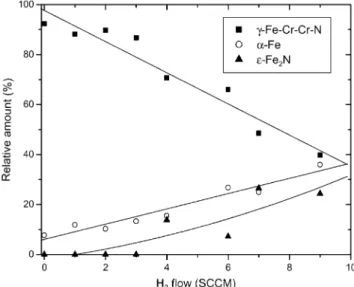
Fig. 5. Evolution of the relative amount of different phases observed using CEMS vs. the hydrogen mass flow.
Fig. 4. Mossbauer spectra measured by CEMS on¨ (a) a-Fe, (b–h) nitrided coatings deposited on low carbon steel substrates. The numbers
indicated in the upper-left corner of each figure represent the hydrogen flows. more efficient when hydrogen is mixed to the reactive gases. Depth profiles of nitrogen shown in Fig. 3a confirm those results. When hydrogen is only due to contamination of the reactive gases (coating number 1), the deposition rate is approximately 5=1015 at. cmy2 but the nitrogen concentration still under 30 at.%(solid
line in Fig. 3a). The hydrogen depth profile (solid line
in Fig. 3b) shows only a contamination at the surface,
which is always present but also a peak at the interface. This local contribution has been attributed to hydrogen contamination of the substrate before deposition. As the hydrogen flow is increasing, the thickness of the depth profile of nitrogen(dashed line in Fig. 3a) is decreasing but the nitrogen concentration is higher than 30 at.%. The depth profiles of hydrogen (dashed line in Fig. 3b) show clearly a non-uniform distribution and an accu-mulation of hydrogen near the interface between the coating and the substrate. This effect has been observed for all measured depth profiles of hydrogen. It can be explained by the mobility of hydrogen, which is more important where the concentration of defects is important.
Combining PIXE and RBS analysis, we can observe that the relative iron, chromium and nickel compositions of all nitrogen-containing coatings are within the speci-fications of AISI 304L stainless steel. As the nitrogen content of the coating increased, these elements decreased proportionally indicating that iron, chromium and nickel atoms are transferred from the target to the sample in constant proportions. Shedden et al. w12x have also reported this behaviour. This is due to sputter yield amplification effect. The differences in partial sputtering yield for nickel, chromium and iron are very small(1.0,
1.1 and 1.0, respectively, for 500 eV Ar ions w20x) and
result in target surface enrichment of the slowest sput-tering element. The target quickly reaches a steady state condition, even though the target surface chemistry is altered.
Fig. 5 shows the relative amount of the different phases observed by CEMS. Using the data from Cook
w21x, the first doublet (ISs0.32 mmys, QSs0.6 mmy
s) has been attributed to gN-Fe-Cr-Cr-N, which is a typical Fe(III) sub spectrum w22x, while the second doublet is due to´–Fe N. It is clearly observed that the2
mainly due to the reducing thickness of the coatings because we can observe more and morea-Fe due to the substrate, but also to the ´-Fe N phase, which appears2 for H flows higher than 4 sccm. For those flows, the2 maximum nitrogen concentration is 32 at. % and corre-sponds to the relative amount of nitrogen in the´-Fe N2 phase.
5. Conclusions
Stainless steel coatings (AISI-304L cathode)
depos-ited at room temperature by DC-magnetron sputtering in a reactive atmosphere containing N and H have2 2 been characterised quantitatively using different nuclear techniques. It has been shown that the deposition rate is directly related to the partial pressure of argon in the chamber. The nitriding of the coating is more efficient when hydrogen is mixed to the reactive gases and the nitrogen phase formed is richer. The nitrogen depth distribution in the layers is flat while hydrogen is mainly concentrated at the surface (contamination) and at the interface where the concentration of defects is more important. The relative amounts of iron, chromium and nickel in the coatings have been measured by PIXE and still in the same proportion than in the AISI 304L cathode target.
CEMS confirms the results observed by PIXE, RBS, NRA and RNRA. We have shown that at low flow of hydrogen, only Fe III is formed, while for higher hydrogen flows, the stoichiometric ´-Fe N phase2 appears.
References
w1x G. Wagner, T. Louis, R. Leutenecker, U. Gonser, Hyperfine
Interactions 46(1989) 501.
w2x T.h. Briglia, G. Terwagne, F. Bodart, C. Qwaeyhaegens, J.
D’Haen, L.M. Stals, Surf. Coat. Technol. 80(1996) 105. w3x D.L. Williamson, J.A. Davies, P.J. Wilbur, Surf. Coat. Technol.
103–104(1998) 178.
w4x O. Ozturk, D.L. Williamson, J. Appl. Phys. 77¨ (1995) 3839. w5x E. Menthe, K.-T. Rie, J.W. Schultze, S. Simson, Surf. Coat.
Technol. 74–75(1995) 412.
w6x G.A. Collins, R. Hutchings, J. Tendys, Mater. Sci. Eng. A139 (1991) 171.
w7x K. Ichii, K. Fujimura, T. Takase, Technol. Rep. Kansai Univ.
27(1986) 135.
w8x M.P. Fewell, D.R.G. Michell, J.M. Priest, K.T. Short, G.A.
Collins, Surf. Coat. Technol. 131(2000) 300. w9x S.D. Dahlgren, Metall. Trans. 1(1970) 3095.
w10x A. Bourjot, M. Foos, C. Frantz, Surf. Coat. Technol. 43–44 (1990) 533.
w11x K.L. Dahm, P.A. Dearnley, Surf. Eng. 12(1996) 61.
w12x B.A. Shedden, F.N. Kaul, M. Samandi, B. Window, Surf. Coat.
Technol. 97(1997) 102.
w13x G. Terwagne, J. Colaux, G.A. Collins, F. Bodart, Thin Solid
Films 377–378(2000) 441.
w14x S. Kumar, M.J. Baldwin, M.P. Fewell, S.C. Haydon, K.T.
Short, G.A. Collins, et al., Surf. Coat. Technol. 123(2000) 29. w15x G. Terwagne, to be published.
w16x G. Terwagne, M. Piette, F. Bodart, Nucl. Instr. Meth. B19y20 (1987) 145.
w17x B. Maurel, G. Amsel, Nucl. Instr. Meth. 218(1983) 159. w18x W.A. Landford, Nucl. Instr. Meth. B66(1992) 65.
w19x D.L. Williamson, F.M. Kustas, M.S. Misra, J. Appl. Phys. 60 (1986) 1493.
w20x D.M. Hoffman, B. Singh, J.H. Thomas III, Handbook of
Vacuum Science and Technology San Diego: Academic Press,
(1998) 611.
w21x D.C. Cook, Met. Trans. A18(1987) 201.
w22x T. Kacsich, M. Niederdrenk, P. Schaaf, K.P. Lieb, U. Geyer,