HAL Id: tel-01339873
https://tel.archives-ouvertes.fr/tel-01339873
Submitted on 30 Jun 2016
HAL is a multi-disciplinary open access archive for the deposit and dissemination of sci-entific research documents, whether they are pub-lished or not. The documents may come from teaching and research institutions in France or abroad, or from public or private research centers.
L’archive ouverte pluridisciplinaire HAL, est destinée au dépôt et à la diffusion de documents scientifiques de niveau recherche, publiés ou non, émanant des établissements d’enseignement et de recherche français ou étrangers, des laboratoires publics ou privés.
Modification of carbon fiber / epoxy matrix interphase
in a composite material : Design of a self-healing
interphase by introducing thermally reversible
Diels-Alder adducts
Wenyong Zhang
To cite this version:
Wenyong Zhang. Modification of carbon fiber / epoxy matrix interphase in a composite material : Design of a self-healing interphase by introducing thermally reversible Diels-Alder adducts. Materials. INSA de Lyon, 2014. English. �NNT : 2014ISAL0127�. �tel-01339873�
N° d’ordre 2014ISAL00127 Année 2014
Thèse
Modification of carbon fiber / epoxy matrix interphase in a
composite material: design of a self-healing interphase
by introducing thermally reversible Diels-Alder adducts
présentée devant
L’Institut National des Sciences Appliquées de Lyon
pour obtenir
Le Diplôme de docteur
École Doctorale: Matériaux de lyon
Spécialité: Matériaux Composites
par
Wenyong ZHANG
Soutenue le 11-12-2014 devant la Commission d’Examen:
JURY
Reviewer Daniel Hanoch WAGNER Professor
(Weizmann Institute of Science, Israel)
Reviewer Michel NARDIN Directeur de recherche CNRS
(Institut de Science des Matériaux de Mulhouse, France)
Examiner Philippe ZINCK Professor
(Université des Science et Technologies de Lille, France)
Supervisor Jean François GÉRARD Professor
(INSA de LYON, France)
Co-Supervisor Jannick DUCHET-RUMEAU Professor
(INSA de LYON, France)
Remerciements
Ces travaux ont été financé par le Conseil de Bourse Chinoise (CSC) et effectués au sein du l’UMR CNRS 5223/Ingénierie des Matériaux Polymères, au Laboratoire de Matériaux Macromoléculaires à l’Institut National des Sciences Appliquées de Lyon.
Tout d’abord, je tiens à exprimer ma plus sincère gratitude au Professeur Jean François GERARD, directeur de la recherche INSA de Lyon, et Professeur Jannick DUCHET-RUMEAU pour m’avoir accueilli dans leur laboratoire et dirigé pendant ces quatre années. Sans leurs précieux conseils, leurs aides efficaces et aussi leurs encouragements, je n’aurais pas fini ces travaux.
Je tiens ensuite à remercier Daniel Hanoch WAGNER, Professeur à L’Institut Weizmann des Sciences, et Michel NARDIN, Professeur à L’Institut de Science des Matériaux de Mulhouse pour avoir accepté d’être les rapporteurs de cette thèse. De plus, je remercie également Philippe ZINCK, Professeur à L’Université des Science et Technologies de Lille, examinateur, pour sa présence et sa contribution à mon jury de thèse.
J’aimerais aussi remercier Laurence MASSIN, ingénieur à l’Institut de Recherches sur la Catalyse et l'Environnement de LYON, pour avoir réalisé les analyses XPS. Je remercie Fernande BOISSON, ingénieur de recherche du laboratoire IMP, et Cécile CHAMIGNON, ingénieur d’étude du laboratoire IMP, pour la réalisation de l’étude RMN. Je voudrais particulièrement remercie Guilhem QUINTARD, Technicien du laboratoire IMP, pour son aide précieuse durant les tests mécaniques. Merci aussi à Georgiy SMOLYAKOV, post-doctorant au laboratoire IMP, qui m’a formé à l’AFM. Je remercie toutes les personnes qui j’ai rencontré durant ma thèse et qui m’ont aidé à la réalisation de ce travail.
Mes remerciements vont également à mes aimables co-bureaux, Marie, Céline,
Elie, Thomas, Noelie, Krisd, Nicolas et Nour qui m’ont accompagné durant ces quatre belles années passées à l’IMP. Je remercie également mes amis chinois, Senbin, Zhen, Jing (il), Xibo, Biao et Jing (elle) pour leur amitié et leurs aides sans réservations. Merci à tous les camarades avec qui ce fût en plaisir de travaille. Enfin, un énorme remerciement à ma famille, mes parents, mon frère et particulièrement à ma épouse qui m’a accompagné pendant les périodes difficiles.
Abstract
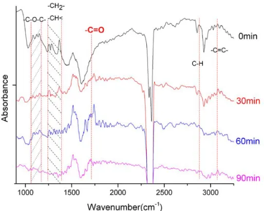
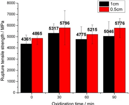
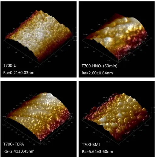
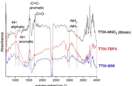
A thermally self-healable carbon/epoxy interphase was designed based on Diels-Alder (D-A) thermally reversible covalent bonds. The D-A modified interphase was formed between maleimide groups grafted on carbon fiber surface and furan groups introduced into epoxy network. The self-healing ability was characterized by a micromechanical approach using the micro-droplet debonding test. In this work, carbon fiber surface underwent a three-step treatment to graft maleimide groups, including HNO3 oxidization, tetraethylenepentamine (TEPA)
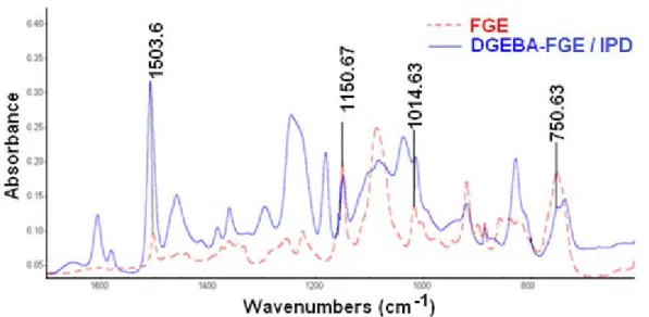
amination, and bismaleimide (BMI) grafting. The fiber surface physico-chemical modifications after each treatment step were characterized by microscopies (SEM, and AFM) and spectroscopies (XPS, and ATR-FTIR). The matrix modification was carried on mixing furfuryl glycidyl ether (FGE) into epoxy/amine network and the properties of modified matrix were studied by TGA, DSC, ATR-FTIR, and tensile tests. The reversible character of Diels-Alder bond was also followed by DSC, TGA, and NMR. The interfacial mechanical properties and the self-healing abilities of the D-A modified interphases, built by combining DGEBA-FGE/amine matrix with a serial of BMI-grafted carbon fibers tuned as a function of the oxidization time were investigated. At last, since FGE plays a double-role in D-A modified interfacial system, i.e. chain extender in epoxy network and self-healing agent in the interphase, the influences of FGE content in matrix on the mechanical properties of interphase and also on the mechanical properties of cured matrix were evaluated. As a consequence, this study allowed to achieve the best process to build a thermally self-healable carbon/epoxy interphase based on thermally reversible Diels-Alder covalent bonds. The formed interphase has not only the successive
self-healable abilities but also the required mechanical properties. Additionally, the
overall mechanical properties of the composite material based on this interphase will not be weakened significantly after the interfacial modifications.
Thesis title: Modification of carbon fiber / epoxy matrix interphase in a composite
material: Design of a self-healing interphase by introducing thermally reversible Diels-Alder adducts
KEY WORDS: Diels-Alder; Interface/Interphase; Self-healing; Carbon Fiber;
Epoxy; Composites; Micro-droplet; Debonding.
Résumé
Une interphase fibre de carbone/matrice époxy thermiquement auto-réparable a été construite sur la base de liaisons covalentes Diels-Alder (D-A) thermiquement réversibles.L’interphase modifiée par D-A a été formée en greffant des groupes maléimide sur la surface de la fibre de carbone et en introduisant des groupes furane dans le réseau polyépoxy. La capacité d’auto-réparation interfaciale a été caractérisée par le test de déchaussement de la micro-goutte. La surface de la fibre de carbone a subi un traitement en trois étapes : (i) oxydation par l’acide nitrique, (ii) amination par la tétraéthylènepentamine (TEPA) et (iii) greffage de bismaléimide (BMI). Après chaque étape de traitement, les modifications physico-chimiques de surfaces de la fibre ont été caractérisées par microscopies (MEB et AFM) et par spectroscopies (XPS, et ATR-FTIR).La modification de la matrice a été effectuée en copolymérisant le furfuryl glycidyl éther (FGE) au
réseau époxy/amine et les propriétés de la matrice ont été évaluées par TGA,
DSC, ATR-FTIR, et traction uniaxiale. Le caractère réversible des liaisons Diels-Alder a été également vérifié par DSC, TGA et RMN.Pour caractériser les capacités d'auto-réparation de l’interphase modifiée par D-A, les propriétés mécaniques et les capacités d'auto-réparation de l'interphase construite en combinant la matrice DGEBA-FGE/amine avec une série de fibres de carbone greffés par BMI ont été mesurées en fonction du temps d’oxydation préalable au greffage (gouvernant la réactivité de la fibre de carbone).Enfin, car le FGE joue un double rôle dans le système interfacial modifié par D-A, à la fois dans l’architecture en intervenant comme allongeur de chaîne entre nœuds de réticulation du réseau époxyde et au niveau de l’interphase en contribuant dans la formation des liaisons réversibles, l'influence de la concentration de FGE dans la matrice a été étudiée sur les propriétés mécaniques de l'interphase et également sur les propriétés mécaniques de la matrice. Par conséquent, ce travail a permis d’aboutir à la procédure optimale pour construire une interphase fibre de carbone/époxy thermiquement auto-réparable basée sur des liaisons covalentes Diels-Alder (thermo réversibles). L'interphase ainsi formée possède non seulement des capacités d’auto-réparations multiples, mais également des propriétés mécaniques compatibles avec une approche ‘matériau composite’. En effet, les propriétés mécaniques globales des matériaux composites, comme attendu, sont dépendantes des caractéristiques de cette interphase mais ne seront pas réduites par la présence de celle-ci notamment pour assurer la durabilité du matériau composite.
Titre de thèse: Modification de l’interphase du matériau composite fibre de
carbone /matrice époxyde: Design d’une interphase auto-réparable basée sur des liaisons Diels-Alder thermiquement réversibles
Mot clés: Liaisons Diels-Alder; Interface/ Interphase; Auto-réparabilité; Fibre de
Table of content:
General introduction
Part I Bibliography
A. Interphase of carbon fiber reinforced epoxy matrix based composite . 7
A.1 Structure of carbon/epoxy interphase ... 7
A.1.1 Dimensions of interphase ... 7
A.1.2 Interfacial adhesion: Basis ... 8
A.1.3 Specific features of the interphase in case of ex-PAN carbon fiber ... 10
A.2 Modification of carbon/epoxy interphase ... 11
A.2.1 Aims of interfacial modifications in carbon fiber/epoxy systems... 11
A.2.2 Modification of carbon fiber surface ... 15
A.2.2.1 Oxidative treatment ... 15
A.2.2.2 Non-oxidative treatments ... 18
A.2.2.3 Fiber surface characterization ... 24
A.2.3 Modification of epoxy matrix ... 25
B. Characterization of interfacial mechanical properties of composite materials ... 27
B.1 Introduction ... 27
B.2 Micron-scale methods ... 28
B.2.1 Single fiber pull-out test ... 28
B.2.1.1 Introduction ... 28
B.2.1.2 Parameters influencing the single fiber pull-out test ... 32
B.2.1.3 Interfacial failure modes ... 37
B.2.1.4 Interfacial failure criteria ... 38
B.2.2 Single fiber fragmentation test ... 42
B.2.3 Single fiber push-out test or micro-indentation test ... 43
B.2.4 Compression test ... 45
B.3 Conclusion ... 46
C. Self-healable composite materials ... 47
C.1 Extrinsic self-healing for polymer materials ... 48
C.1.1 Embedded microcapsules ... 49
C.1.2 Embedded hollow fibers ... 51
C.1.3 Tri-dimensional microvascular network ... 52
C.2 Intrinsic self-healing for polymer materials ... 55
C.2.2 Self-healing process based on reversible bonds ... 57
C.2.2.1 Reversible covalent bonds ... 57
C.2.2.2 Supramolecular assemblies ... 61
C.2.2.3 Metal ligands ... 64
C.3 Selection of a strategy for interfacial self-healing ... 66
D. Conclusion ... 71
Part II
Design and characterization of a self-healable
interphase
A. Methodology to generate a self-healable carbon/epoxy interphase ... 75B. Carbon fiber surface treatments and characterizations ... 76
B.1 Introduction ... 76
B.2 Carbon fiber surface treatment ... 78
B.3 Characterization of carbon fiber at different treatment steps ... 80
B.3.1 Characterization of carbon fiber after oxidization step ... 81
B.3.1.1 Selection of initial carbon fiber ... 81
B.3.1.2 Fiber surface topography after oxidization step ... 83
B.3.1.3 Carbon fiber surface chemical composition after oxidization step ... 85
B.3.1.4 Influence of HNO3 oxidization on fiber mechanical properties ... 87
B.3.2 Characterization of carbon fiber after grafting with TEPA and BMI ... 89
B.3.2.1 Selection of amination agent ... 89
B.3.2.2 Fiber surface topography after grafting with TEPA and BMI ... 90
B.3.2.3 Fiber surface chemical composition after grafting with TEPA and BMI ... 91
B.3.3 Conclusion ... 94
C. Epoxy matrix composition and characterization ... 95
C.1 Composition and curing of matrix system ... 95
C.2 Matrix characterization ... 97
C.2.1 Chemical structure of fully cured furan-functionalized epoxy networks ... 97
C.2.2 Physical properties of furan functionalized epoxy network ... 98
D. Formation and evaluation of thermally reversible self-healable interphase ... 100
D.1 Investigation of Diels-Alder reaction ... 100
D.2 Formation of interphase containing thermo-reversible bonds ... 105
D.3 Interphase micromechanics: micro-droplet debonding test ... 108
D.3.2 Process of test ... 109
E. Conclusion ... 112
Part III
Interfacial mechanical properties and self-healing
ability of conventional carbon/epoxy interphase
A. Introduction ... 117B. Sample geometrical parameters for micro-droplet debonding test .. 118
B.1 Inter-relationship and significance of embedded length (Le), droplet diameter (Dd), and contact angles (θ and ϕ) ... 118
B.2 Significance of free length (Lf) ... 122
B.3 Statistics of fiber diameter (Df) ... 124
C. Interfacial mechanical properties ... 124
C.1 Interfacial fracture mode analysis ... 124
C.2 Analysis of debonding process(es)... 126
C.2.1 Analysis of the first debonding force ... 126
C.2.2 Definition of the embedded length (Le) range ... 129
C.2.3 Analysis of the second debonding force ... 130
C.2.4 Analysis of the frictional force ... 131
C.3 Determination of the interfacial shear strength (IFSS)... 132
C.3.1 Interfacial shear strength measured during the first debonding (IFSS1) ... 132
C.3.2 Interfacial shear strength measured during the second debonding (IFSS2) ... 134
C.3.3 Evaluation of the interfacial shear strength of the four reference interphases 135 D. Evaluation of interfacial self-healing ability ... 136
E. Conclusion ... 139
Part IV
Interfacial mechanical properties and self-healing
ability of D-A modified interphase
A. Influence of carbon fiber surface treatment on interfacial mechanical performances and interfacial self-healing ability of the D-A modified interphase ... 145A.1 Introduction ... 145
A.3 Analysis of interfacial shear strength ... 148
A.4 Evaluation of interfacial self-healing ability ... 150
A.4.1 Feasibility of interfacial self-healing ... 150
A.4.2 Interfacial self-healing efficiency... 155
A.4.3 Comparison healing abilities of the different D-A modified interphases ... 157
A.4.4 Repeatability of interfacial self-healing ... 160
A.5 Conclusion ... 162
B. Influence of FGE content on D-A modified interphase properties .... 164
B.1 Introduction ... 164
B.2 Influence of FGE content on the interfacial mechanical properties ... 165
B.2.1 Influence on the interfacial bonding strength ... 165
B.2.2 Influence of FGE content on the interfacial toughness ... 166
B.3 Influence of the FGE content on the interfacial self-healing efficiency... 168
B.3.1 Characterization of the interfacial self-healing efficiency based on IFSS ... 168
B.3.2 Characterization of interfacial self-healing efficiency based on Gic ... 170
B.4 Conclusion ... 173
General conclusions and perspectives ... 175
Annexe ... 181
General introduction
A composite material is defined as a material that is constituted with two phases: matrix phase and reinforcing phase. The chemical or/and physical properties of these two phases are usually different and must be assort with each other. The combination of them should produce a synergy effect and lead to some new properties or even bring a new function to the material. Any material coincident with above conditions at the same time can be considered as composite material. The excellent properties of composite materials such as high specific strength, high specific modulus, and relatively high toughness combined with simple processes make them widely used in some industrial fields. For example, in the aeronautics and aerospace fields, the structural material should be not only strong enough to ensure the security but also light enough to reduce the transport cost. However, for the conventional materials (aluminium-based materials), the safety issues are proportional to the weight. As a consequence, composite materials, especially the carbon fiber reinforced advanced composite materials, get more and more interests in these fields. Furthermore, the applications of composite materials in the fields of civil industries have also developed significantly such as in automobile industry and sports equipment. Nowadays, the environmental pollution caused by automobile has been more and more serious. Using polymer based composite materials to replace conventional metallic material can effectively reduce the dead weight of cars and thus decreasing the consumption of fossil fuels. As the development of composite materials, its application range is broadening gradually and almost involves all the industries.
area, named interface. However, the researchers have confirmed [Drzal1983,
Wu2014]that an interface of a composite material is not two-dimensional (2D), but a narrow region formed by interpenetration between matrix and reinforcing material (and/or its surface treatment) at a sub-micronic or nanometric scale. The structural, physical, chemical, and mechanical properties of this region are totally different to the neat constituent ones. For this reason, this area is further named as ‘interphase’ but not interface. In a composite material, the interphase always plays a very important role. For example, as a carbon fiber-based composite material undergoes a sudden impact, it will instantaneously appear a huge number of micro-cracks mainly in the interphase region. The appearance of these micro-cracks can absorb a large part of impact energy and can improve the toughness of the material. In fact, the interphase is a transition layer where stress concentration and defects happen. In the early stage of loading of a composite material, the existing defects and stress concentration will trigger a large number of imperceptible micro-cracks in the region of interphase. If we do nothing for these cracks, they will continue to propagate in the process of use and extend inside matrix until the whole material is broken. This broken process is unavoidable for all composite materials. For any type of loading conditions (tensile, compression, flexural, shearing, and torsion), the load applied on the matrix will be transmitted through interphase to the reinforcing phase, thereby the mechanical properties of the material will be improved.
The aim of this PhD thesis is to design a carbon fiber and epoxy based composite material whose interphase has a thermal self-healing ability. In other words, the micro-cracks in interphase of this type of composite material would be healed by heating, i.e. the life of use can be extended and catastrophic failure of
the composite material can be avoided. The realization of this subject is based on
building a carbon/epoxy interphase from conventional thermally reversible Diels-Alder (D-A) bonds resulting from the reaction between furan and maleimide groups. As micro-cracks appear in the interphase region, a subsequent heating will allow the D-A adducts on the corresponding surfaces of the cracks to re-establish between crack lips. Moreover, this healing process can be repeated many times.
Part I summarizes some conventional methods used to evidence interfaces
and main features about carbon fiber/epoxy interphase modification, interphase mechanical characterization, and self-healing applied to polymer and composite materials. After this part, the most relevant methodology for designing a self-healable interphase as well as the characterization methods will also be proposed.
Part II details the protocols for modifying carbon fiber surface and matrix that
will considered for designing self-healable interphase. The micro-droplet debonding test will be introduced for characterizing interfacial mechanical properties and self-healing efficiency.
Part III is dedicated to the characterization of the interfacial mechanical
properties of conventional carbon/epoxy interphases (non-D-A modified, i.e. considered as ‘references’) using the micro-droplet debonding test and the relevant sample geometrical parameters will be optimized. The mechanical properties and self-healing abilities of these reference interphases will be also discussed.
Part IV reports the discussions of experimental results of micro-mechanical
test on interphases designed to be self-healable. The feasibility of Diels-Alder reaction based self-healing interphase is confirmed and the best conditions of fiber
surface treatment and matrix modification are determined. In this part, the
interfacial mechanical properties of this self-healing interphase are also discussed. Finally, the conclusions are summarized in Part V and some perspectives are discussed.
Part I Bibliography
A. Interphase of carbon fiber reinforced epoxy matrix based composite . 7
A.1 Structure of carbon/epoxy interphase ... 7
A.1.1 Dimensions of interphase ... 7
A.1.2 Interfacial adhesion: Basis ... 8
A.1.3 Specific features of the interphase in case of ex-PAN carbon fiber ... 10
A.2 Modification of carbon/epoxy interphase ... 11
A.2.1 Aims of interfacial modifications in carbon fiber/epoxy systems... 11
A.2.2 Modification of carbon fiber surface ... 15
A.2.2.1 Oxidative treatment ... 15
A.2.2.2 Non-oxidative treatments ... 18
A.2.2.3 Fiber surface characterization ... 24
A.2.3 Modification of epoxy matrix ... 25
B. Characterization of interfacial mechanical properties of composite materials ... 27
B.1 Introduction ... 27
B.2 Micron-scale methods ... 28
B.2.1 Single fiber pull-out test ... 28
B.2.1.1 Introduction ... 28
B.2.1.2 Parameters influencing the single fiber pull-out test ... 32
B.2.1.3 Interfacial failure modes ... 37
B.2.1.4 Interfacial failure criteria ... 38
B.2.2 Single fiber fragmentation test ... 42
B.2.3 Single fiber push-out test or micro-indentation test ... 43
B.2.4 Compression test ... 45
B.3 Conclusion ... 46
C. Self-healable composite materials ... 47
C.1 Extrinsic self-healing for polymer materials ... 48
C.1.1 Embedded microcapsules ... 49
C.1.2 Embedded hollow fibers ... 51
C.1.3 Tri-dimensional microvascular network ... 52
C.2 Intrinsic self-healing for polymer materials ... 55
C.2.1 Self-healing based on thermoplastic polymer ... 56
C.2.2 Self-healing process based on reversible bonds ... 57
C.2.2.1 Reversible covalent bonds ... 57
C.2.2.2 Supramolecular assemblies ... 61
C.2.2.3 Metal ligands ... 64
Part I Bibliography
A. Interphase of carbon fiber reinforced epoxy matrix based composite
A.1 Structure of carbon/epoxy interphase
The interphase formed between a carbon fiber and an epoxy matrix displays specific features. Its nature is not a simple contact surface between carbon fiber and epoxy matrix, but a interpenetration and ‘connection’ of each of the two phases from physical or/and chemical effects. The interpenetration and ‘connection’ of each phase not only makes interphase have a certain thickness, but also leads to generate different physic-chemical properties to the interphase. This section will describe in detail the structure of interphase formed between carbon fiber and epoxy resin, including the dimensions of interphase, the interfacial adhesion, and some limitations of interphase.
A.1.1 Dimensions of interphase
The earliest definition of interphase can be dated back to the year of 1974 [Metcalfe1974]. The researchers, at that time, considered interface as a layer with certain thickness but not a mathematical plane (2D). However, they did not know the exact structure of interphase because of the limit of characterization techniques. In the early 1990s, Guigon et al. [Guigon1991, Guigon1992,
Guigon1994] firstly characterized the micro-structure of interphase in carbon fiber reinforced composite by using high resolution transmission electron microscopy (HRTEM). According to the TEM images, the existence of the interface was confirmed to be a layer with a certain thickness which is resulted from
inter-diffusion and interaction between the fiber surface and the polymer matrix.
However, their research works did not indicated the precise dimensions of interphase. In 2013, Wu et al. [Wu2014] measured the thickness of T300/epoxy interphase by TEM. For getting an accurate result, the ion etching technique was used to treat sample surface. The sliced sample was observed under various directions of incident electron beam. According to the phase-contrast, the position and micro-structure of the interphase were identified and the interphase thickness was evaluated to be about 200 nm (Fig. I-1).
Figure I-1. TEM image of T300/epoxy interphase [Wu2014].
A.1.2 Interfacial adhesion: Basis
The bonding mode of interphase is an extremely complex theme, which is governed by the physicochemical properties of fiber surface and matrix. Generally, the formation of interphase is considered as the result of two effects: chemical effect and physical effect [Kinloch1980, Wake1978, Kim1998]. The ‘chemical
compatible chemical groups of matrix to form chemical bonds, by which the fiber
surface and matrix are combined together. The ability of the interphase to transfer stress from the polymer matrix to the fiber depends on the number and bond energy of the bonds existing at the interphase. About ‘physical effect’ based adhesion theory, four acceptable origins could be considered [Kinloch1980]: mechanical interlocking, diffusion, electrostatics, and adsorption. The mechanical
interlocking theory states that the polymer chains could enter and anchor in the
graphite layers at the fiber surface (cavities and micro-grooves) or tangles with surface polymer chains (for coated fiber), by which fiber surface and matrix are interlocked. The effect of interlocking is determined by fiber surface topography and the polymer chain mobility during contact, i.e. processing. The diffusion
theory proposes that the molecules of two different phases diffuse into each other.
Obviously, this theory can’t be considered for explaining the formation of an interphase between carbon fiber and a polymer, except if the fiber surface was coated previously. In the later case, the inter-diffusion occurs between the polymer chains and the components of the coating/sizing layer. The electrostatic theory states that the electrostatic charges between fiber and matrix are different and the interaction of positive and negative charges (electrostatic force) can lead to interfacial bonding which depends on the charge density. Although electrostatic force is usually tiny between fiber and matrix, it can be strengthened when the fiber surface is treated with some specific coupling agents. The absorption theory is the most generally accepted one. The involved adhesion forces are so-called secondary forces, including Van der Waals’ force and hydrogen bonds. In general, the secondary forces could be considered as non-efficient for interfacial bonding. In fact, for the most of interphases encountered in fiber based composite materials,
the interfacial adhesion strength can’t be explained with only one of the theories
mentioned above. One needs to consider all of them depending on the chemistry of the fiber surface, topography, and the physicochemical properties of the matrix.
A.1.3 Specific features of the interphase in case of ex-PAN carbon fiber
It’s well-know that carbon fiber has a specific turbostratic structure which is composed by crystallized graphite planes, as schematically shown in Figure I-2. These disordered carbon layers are covered by a thin skin of few well-organized basal planes [Guigon1994]. This special structure makes the carbon fiber surface be very inert and only few functional groups are present on it. Thus, it’s impossible to form a large number of chemical bonds between carbon fiber without any surface treatment and epoxy matrix. Moreover, the surface energy of graphite plane is extremely low, which makes absorption theory irrelevant on a carbon fiber surface. For these reasons, the interface of composite material reinforced by carbon fibers without any treatment will be very weak. That is the reason for which there are so many investigators interested in carbon fiber surface modification to promote interfacial adhesion.
In a composite material, the function of interphase, besides combining fiber
surface and polymer matrix, is to transfer stress from the matrix phase to reinforcing fiber leading to reinforcement. However, the mechanical properties of reinforcing material and matrix are extremely different, especially for carbon fiber and epoxy matrix. These obvious differences will lead to stress concentration close to the interface, i.e. in the interphase. In other words, when a composite material is loaded, the interphase could be damaged before other regions of the composite material.
The first specific feature described above related to an intrinsic limitation of carbon fiber to establish required interfacial interactions which can be improved by fiber surface modification. However, the second feature which exists in all kinds of composite materials, i.e. enhanced stress application to the interphase, can’t be avoided but can be optimized from interphase design.
A.2 Modification of carbon/epoxy interphase
Interphase is a transition region formed by the fiber surface and the matrix. For optimizing its structure and properties, the structure and properties of fiber surface and matrix should be considered independently or simultaneously.
A.2.1 Aims of interfacial modifications in carbon fiber/epoxy systems
Carbon fiber is a relevant reinforcing material for composite due to its high specific strength and modulus. Nevertheless, the inert character of its graphite-like surface limits the adhesion with polymer matrices such as epoxy network. Thus, the most important objective for interfacial modification is the improvement of the interphase region as it plays an essential role for transferring stress from the
polymer matrix to the fiber and it’s the place for stress concentration. As a
consequence, the elastic behavior and toughness of the interphase are essential. As a conclusion, the interface/phase modification is motivated according to the following requirements:
a) Interface/phase strengthening
Improved interfacial properties can be achieved from the generation of interfacial chemical bonds and/or physical effects. The majority of fiber surface treatments offer to introduce active functional groups on fiber surface, especially after oxidization and grafting treatments. Some of these groups can react with the reactive functional groups of the matrix and form interfacial chemical bonds. These bonds can dramatically increase the interfacial strength. For example, Peng et al. [Peng2013] introduced a large amount of primary and secondary amine groups on carbon fiber surface by means of grafting method. As the treated fibers are combined with epoxy matrix to form carbon fiber reinforced composite materials, these amine groups on fiber surface act as a curing agent. The authors highlighted that the interfacial shear strength (IFSS) after treatment displays an increase of 85% compared to that without treatment (Fig. I-3). Furthermore, almost all the active functional groups introduced by surface treatment are polar groups. For a polar epoxy matrix, these polar groups on the fiber surface can undoubtedly promote the wettability of matrix, phenomenon very important for interfacial adhesion.
Figure I-3. Evolution of the interfacial shear strength (IFSS) as a function of the concentration of poly(amidoamine) (PAMAM) [Peng2013].
Some treatments methods can also etch fiber surface, as the weak layer and attached particles on fiber surface are removed leading to a rougher fiber surface. The rough surface is favorable for physical anchoring of matrix increasing the interfacial adhesion strength. When the etching effect is strong enough, some micro grooves or cavities are formed on fiber surface (Fig. I-4). Some of scientists [Rashkovan1997, Meng2013, Yu2014] considered these grooves and cavities as surface defects which will affect mechanical properties of carbon fiber and also mechanical performances of the resulting composite material. However, others [Zhang2004, Li2008] indicated that these ‘defects’ allowed matrix chain segments to enter leading to a good mechanical interlocking with matrix, which is an efficient way to get high stress transfer levels. Connecting (by grafting or CVD) carbon nanotubes on fiber surface to form a multi-scale reinforced composite material is a relatively new subject. But its interfacial strengthening principle is not very clear nowadays.
Figure I-4. AFM images of treated and untreated ex-PAN carbon fiber surface [Meng2013].
b) Interphase toughening
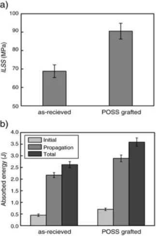
Hitherto, few works deal with the interphase toughening. A simple concept for interphase toughening is to introduce some flexible polymer chains between fiber and matrix. Varelidis et al. [Varelidis1999] have studied the interlaminar fracture toughness of carbon fiber reinforced composite material, whose reinforcing carbon fibers were coated with polyamide 66 (Nylon66). The results indicated that the flexible chains of Nylon66 existing in interphase surely increased the interfacial fracture toughness. In this system, there is not chemical bond between Nylon66 and fiber surface. So it’s impossible to get an ideal interfacial strength. Zhao et al. [Zhao2010] have grafted a layer of uniform octaglycidyldimethylsilyl POSS on carbon fiber surface. This flexible layer of silicone increased impact toughness from 2.62 to 3.59 J. Simultaneously, the interlaminar shear strength (ILSS) has also been increased from 68.8 to 90.5 MPa, which can be attributed to the covalent bonds formed between POSS and fiber surface (Fig. I-5).
Figure I-5. Mechanical properties of the composite materials based on untreated and POSS-grafted carbon fibers. a) ILSS and b) impact toughness [Zhao2010].
A.2.2 Modification of carbon fiber surface
Carbon fiber surface treatment can be generally classified into two types: oxidative and non-oxidative treatments. According to oxidative medium, oxidative treatments are further divided into dry oxidization and wet oxidization [Kim1998].
A.2.2.1 Oxidative treatment a) Wet oxidization
Wet oxidization treatments are achieved in liquid oxidizing agents, such as nitric acid [PittemanJr1997, Wu1995, Serp1998], hydrogen peroxide [Meng2013,
Guo2009], supercritical water [Bai2010], and potassium persulfate [Yu2014] etc. For increasing the oxidization efficiency, these oxidizing agents generally can be used together with some additives. For example, Bai et al. [Bai2010] investigated
the oxidization effect of supercritical water on carbon fiber surface. They found that
it had a slight ability to oxidize carbon fiber surface. However, when they added oxygen into the supercritical water, the oxidization ability increased strongly. In addition, the researchers have also found that the carbon fiber surface topography might be changed by etching effect of the oxidization agent [Yu2014]. For example, the pits and/or grooves appear on fiber surface. These pits and/or grooves can even damage the original mechanical properties of carbon fiber when the number or the deepness of them reaches a certain value. The change of topography depends on oxidization conditions, including the type of oxidizing agent, oxidization temperature, and exposure time. For example, both Pittmanjr [PittmanJr1997] and Serp [Serp1998] have tried to treat the carbon fiber surface by nitric acid with a same concentration. The treatment conditions of Pittmanjr are 115°C for different times from 20min to 90min, while the Serp’s conditions are 80°C for 300min. The different temperatures and durations of oxidization treatments lead to almost opposite conclusions. Pittmanjr indicated that the amount and dimension of pits on fiber surface increased with oxidization time, whereas Serp [Serp1998] concluded that the fiber surface morphology was not affected significantly for the considered conditions.
The other wet oxidization treatment which proceeds faster and uniformly is commonly used for commercial carbon fibers. It’s denoted as electrolytic or anodic oxidization [Park2000]. This method proceeds with considering the carbon fiber as anode in an electrolytic reaction with different electrolyte, for example sulphuric acid aqueous, ammonium bicarbonate, or sodium hydroxide [Kozlowski1984]. This electrolytic treatment introduces active functional groups on surface and dramatically changes the topography of fiber surface.
b) Dry oxidization
Dry oxidization treatment is carried out in atmosphere of gas. The gas can be some oxygen containing gases such as oxygen [Boudou2003], ozone [Li2008], carbon dioxide [Serp1998], and air [Fukunaga1999, Zhang2004, Lee1997,
Xie1990] etc. Although the most part of these gases are oxidative at room temperature, their oxidizing power is not sufficient for treating the extremely inert carbon fiber surface and this treatment process always needs to be performed at a relatively high temperature. Zhang et al. [Zhang2004] have oxidized carbon fiber surface under air atmosphere with varying temperature, included between 450 and 600 °C during 1 hour. They have shown that, at 450 °C, fiber surface morphology does not change in a large way compared with the untreated fiber. While, when the temperature increases to 500 °C, the fiber surface becomes relatively rough and some pieces of tiny fragments appear on fiber surface. At 600 °C, the oxidization becomes more aggressive and a large number of micro-pits could be generated on the fiber surface. Obviously, the carbon fiber surface treatment in air with high temperature has a negative effect on structure of fibers, and therefore damaging their mechanical properties. In fact, no matter the nature of the gas, the strong oxidizing character under high temperature of these gases will etch fiber surface significantly. The plasma oxidization is another relatively mild treatment which will not etch fiber surface significantly [Boudou2003]. This treatment is apt to turn oxygen containing gases into plasma. The electric particles (ion and free electron) in plasma atmosphere will attack fiber surface and will provide a large amount of oxygen functional groups on fiber surface. Although this method seems more suitable for carbon fiber surface treatment, it needs a special plasma reactor.
consequence: the amount of oxygen-containing functional groups on fiber surface
will be more or less increased. When the treatment conditions are strong enough, the fiber surface might be etched and even lead to lower mechanical properties of fibers. Figure I-6 displays the possible functional groups existing on fiber surface after oxidization treatments.
O O C O C C O OH OH O O O OH O O O O
Carboxyl Phenolic Hydroxyl Quinone-type Carbonyl
Normal Lactone Fluorescene type lactone
Carboxylic Acid Anhydride
Cyclic Peroxide
Figure I-6. Generated functional groups on fiber surface after oxidization treatment of ex-PAN carbon fibers [Jones1991].
A.2.2.2 Non-oxidative treatments
The non-oxidative treatments do not change the chemical structure of fiber surface itself, but could introduce some additional reactive species close to the fiber surface. This method will not influence the mechanical properties of carbon fiber and generally can effectively improve the interfacial properties.
a) Coating/sizing
The coating consists in forming an extremely thin polymer layer on the fiber surface, which is usually considered for commercial carbon fibers. The coating could be either applied from a solution or an emulsion of polymer(s) and additive(s) [Guigon1994, Cheng1994, Paipetis1996, Broyles1998, Dilsiz1999, Dilsiz2000,
Dai2011, Zhang2012]. The coating mainly has two functions [Paipetis1996,
Dilsiz2000]: 1) protection of fiber surface during fiber handling and re-processing as well as composite manufacturing; 2) promotion of fiber surface wettability and further increase of the interfacial adhesion. The first function is accepted almost by all the researchers in composite field. However, the second objective could be considered according to different ways. Dilsiz et al. [Dilsiz1999, Dilsiz2000] studied the physic-chemistry of the fibers coated with polyetherimide and poly (thiol- arylene phosphine oxide). They mentioned that coating can induce a decrease of both polar and dispersive components and surface functional groups concentration. While, Dai et al. [Dai2011] proposed an opposite conclusion by studying commercially coated carbon fibers (T300B and T700SC), i.e. coated fiber surface have a higher concentration of activated carbon atoms and a higher polar surface energy than that of non-coated fiber. It means that the type of coating agent directly determines the physicochemical nature of the fiber surface which is contact with the polymer matrix. Additionally, the second function of coating layer heavily depends on the compatibility between coating layer and matrix [Cheng1994, Guigon1994]. For example, Yumitori et al. [Yumitori1994] have reported that the carbon fiber coated with brominated epoxy resin can effectively improve the interphase with the polyethersulfone (PES) matrix, whereas it leads to a weak interphase in the case of epoxy matrix system. For PES matrix, strong
dipolar-dipolar interactions take place between bromine atoms from the fiber
coating and PES, leading to interpenetration between coating layer and matrix. But for epoxy matrix, this kind of interaction does not exist and only physical absorption occurs between sizing layer and matrix (Fig. I-7). Besides these parameters, the state of coating components before deposition (polymer solution or emulsion) [Cheng1994], the coating layer thickness [Gerard1988], and the molecular weight of coating components [Zhang2012] also play a key role.
Figure I-7. Interphase structures between Br-epoxy coated carbon fiber and two different polymer matrices [Yumitori1994].
b) Surface grafting
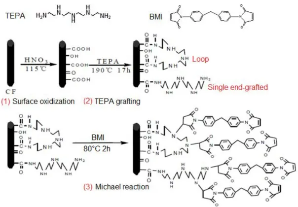
The surface grafting is one of the most effective methods to activate and/or functionalize carbon fiber surface. The grafted materials can be multifunctional polymer chains, and covalently bonded carbon nanotubes, etc. For example, Pittmanjr et al. [PittmanJr1997a] grafted long-chain tetraethylenepentamine (TEPA) onto nitric acid oxidized ex-PAN carbon fiber surface, resulting in a dramatic increase of the amount of amine groups on fiber surface (Fig. I-8). These amine groups can significantly increase the wettability of fiber surface and can be reacted during curing in the case of epoxy matrix based composite material. For
introducing more active amine groups on fiber surface, poly(amido amine)
(PAMAM) dendrimer that contains more -NH2 and -NH- has been also used
[Peng2013, Mei2010].
Figure I-8. Proposed mechanisms of grafting tetraethelynepentamine (TEPA) onto oxidized carbon fiber surface [PittermanJr1997a].
Carbon nanotubes (CNT) could be also grafted on the carbon fiber surface to design high performance multi-scale reinforced composite materials [He2007,
Laachachi2008]. For example, Laachachi et al. [Laachachi2008] have treated CNT and CF by acid oxidization and thermal treatment, respectively. These protocols allowed to form covalent bonds between CNT and CF, i.e. to attach the CNTs onto carbon fiber. Figure I-9 simply demonstrates this grafting process. For increasing the grafting efficiency of CNT, Mei et al. [Mei2010] have also grafted PAMAM on oxidized carbon fiber surface in order to increase the quantity of active points (-NH2 and -NH-) that can react with oxidized CNT.
Figure I-9. Chemical bonding of functionalized nanotubes on carbon fibers from subsequent esterification, anhydridation or amidization of carboxyl groups formed during oxidization treatment
All the grafting methods mentioned above are based on oxidized carbon fibers.
Actually, some grafting reactions on carbon fiber surface can be carried out directly without any prior treatment. In Section A.1, we mentioned that initial carbon fiber (without any treatment) was covered by a thin skin of a few well-organized graphite-like planes. However, these graphite crystalline planes are not perfect and numbers of defects exist. Close to the defects and at the edge of planes, C=C double bonds could be identified, as well as some double bonds even conjugated [Stein1985]. The double bonds on carbon fiber surface provide a possibility to graft polymer chains directly on its surface. Barbier et al. [Barbier1990] have electrochemically oxidized ethylene-diamine, by which radical cations were produced. These radical cations can attack fiber surface double bonds to form C-N covalent bonds, thereby grafting ethylene-diamine on fiber surface. Moreover, this grafting method can be used for a wide variety of molecules which offers a great scope of possible surface modification. Peng [Peng1995] and Buttry [Buttry1999] have indicated that the double bonds on carbon fiber surface can be considered as electrophile allowing the reaction with nucleophilic amine groups following a
Michael-like addition. This reaction allows to graft any long-chain molecules
containing amine groups on fiber surface both at room and elevated temperatures. Subsequently, Severini et al. [Severini2002] have also proposed to graft maleic anhydride or tetracyanoethylene on conjugated C=C bonds on the fiber surface by Diels-Alder addition. Although direct grafting reaction on inert carbon fiber surface is possible, the grafting efficiency is significantly limited by the number of defects on fiber surface. As a consequence, these surface treatment methods were not reported many times in the literature.
c) Others
The above parts introduced the conventional non-oxidative methods for carbon fiber surface. In fact, other specific non-oxidative methods have been mentioned somewhere, such as chemical vapor deposition (CVD). Zhu et al. [Zhu2003] synthesized carbon nanotube on carbon fiber surface by using CVD. The gas for nanotube synthesis was a mixture of methane and hydrogen with different contents of methane. Iron nanoparticles were deposited on fiber surface as catalyst. By considering this method, carbon nanotubes successfully grew on the fiber surface with a relatively low reaction temperature (650-800°C). Zhao et al. [Zhao2005] reported that CVD with floating catalyst method is more favorable for the growth of CNT on carbon fibers compared to the conventional thermal CVD and the morphology of new formed nanotube significantly depended on the reaction temperature. Low temperature deposition leads to produce short MWCNTs with larger diameter while high temperature allows to make long MWCNTs with a smaller diameter. The hyper-thermal and hypo-thermal treatments have also been checked by some investigators. Wang [Wang2006] and Dai [Dai2011a] heated carbon fibers under vacuum at different high temperatures. They found that high temperature could improve the thermal stability and the degree of graphitization of carbon fiber and decrease the amount of functional groups on the surface. This treatment could be achieved not only under vacuum but also under some inert atmosphere [Lee1997]. The hypo-thermal treatment [Rashkovan1997, Zhang2004] of carbon fibers could occur in some liquid gas media which are at extremely low temperature, for example, liquid carbon dioxide, nitrogen, helium, or their vapors. After treatment, the weak layer and attached particles on fiber surface will be removed and fiber surface becomes rougher.
A.2.2.3 Fiber surface characterization
After treatment, both the surface topography and surface chemical structure will be changed on a small scale. How to characterize these changes has become one of the most popular subjects in the field of carbon materials. The development of new modern microscopy techniques allow to observe fiber surface at nanometer scale or even at the scale of a few atoms, such as transmission electronic microscopy (TEM) and atomic force microscopy (AFM). Other techniques, for example gas absorption, and Raman microprobe spectrometry (RMS) etc. can also be used to analyze fiber surface quantitatively. About the surface chemical composition, X-ray photoelectron spectroscopy (XPS), Attenuated Total Reflectance Fourier Transform Infrared spectroscopy (ATR-FTIR), and inverse gas chromatography (IGC) are conventional methods that can be used for qualitatively or semi-quantitatively analyzing the fiber surface. Although acid and base uptake can estimate the content of acidic and basic functional groups on fiber surface, its precision is affected by many factors. Table I-1 lays out some well-known methods for carbon fiber surface characterization.
Technique Characteristic Reference
Scanning electron microscope (SEM)
Direct observation of the fiber surface with high magnification
Morita1986, Smiley1993, Boudou2003
Atomic force microscope (AFM)
3D surface topography of fiber and measurement of surface roughness
Smiley1993
Gas absorption Determination of fiber surface
area and pore volume Boudou2003 Raman microprobe spectrometry
(RMS)
Characterization of the surface regularity of fiber with about 100 nm analysis depth
Inverse gas chromatography (IGC)
Determination of dispersive part of surface free energy (γsd) and
acidity and basicity constants of fiber surface
Vickers2000, Lindsay2007,
Narjes2007
X-ray photoelectron spectroscopy (XPS)
Quantification or
semi-quantification of surface functional groups concentration
Kozlowski1984, Wang2000, Bradley1993, Smiley1993, Gardner1995, Gardner1996, Vickers2000, Pamula2003 Lindsay2007 Ion-scattering spectroscopy (ISS)
Determination of mass spectrum of the outermost one or two atomic layers on the carbon fiber surfaces. Be used as a
complementarity of XPS
Gardner1995, Gardner1996
Attenuated total reflectance Fourier transform infrared spectroscopy (ATR-FTIR)
Quantitative analysis of the functional groups on fiber surface
Sellitti1990, Ohwaki1993, Pamula2003
Acid and base uptake
Determination of the content of acidic and basic functional groups on fiber surface
Pamula2003, PittmanJr2004
Solid state Nuclear Magnetic Resonance (CP-MAS NMR)
Analysis of the chemical
composition of fiber surface with a relatively low resolution
Morita1986
Electron energy loss spectroscopy (EELS)
Determination of the atomic content of low atomic mass elements (C, N, O) on fiber surface
Morita1986, Pamula2003
Table I-1. The methods for carbon fiber surface characterization.
A.2.3 Modification of epoxy matrix
For improving interfacial performance of carbon fiber reinforced composite material, the researchers have paid large attention to treat the inert carbon fiber surface. However, there are few works which considered the direct design of the interfacial region, i.e. the interphase, from the modification of matrix close to the
fiber surface in order to improve interfacial performances. In fact, the interfacial
improvement can be also achieved by matrix modification. He et al. [He2010] compared the interlaminar shear strength (ILSS) of carbon/epoxy composites as a function of epoxy nature. They reported that the more epoxy groups existed in the epoxy prepolymer, the better the ILSS was. Hence it can be predicted that the bonding strength between fiber and matrix can be achieved by introducing more functional groups on prepolymer of matrix by chemical modification. These functional groups should be able to react with the functional groups on fiber surface or physically interact with fiber surface. Unfortunately, very few works deals with that. Another matrix modification tends to add a second reinforcing phase to improve the interfacial properties. For example, Jiang et al. [Jiang2008] added a certain ratio of fullerene nanoparticles in epoxy matrix to improve the interfacial properties of carbon fiber reinforced composite material. The interfacial bond strength between carbon fiber and epoxy matrix was seriously enhanced. This method can be considered not only as matrix modification to ameliorate the interfacial properties but also as the constitution of a multi-scale reinforced composite material. Additionally, the interfacial performance can be improved by changing the physical state of low viscosity matrix. For example, Huang et al. [Huang2002] treated liquid matrix by ultrasound before making a carbon fiber reinforced composite material. The interfacial properties were improved and they attributed this phenomenon to ultrasonic treatment that has mixed matrix more uniformly and decreased its viscosity.
B. Characterization of interfacial mechanical properties of composite materials
B.1 Introduction
The interfacial modification methods mentioned-above are mainly applied to improve the mechanical properties of interphase, for example interfacial strength and toughness, thereby obtaining an optimized composite material. For studying the effect of these interfacial modifications, relevant characterization methods should be considered. Until now, the methods for interfacial characterization can be classified into two types according to the scale of measurement, including micron-scale and macro-scale. The micron-scale methods are generally carried out with a micro-composite which is composed by a single fiber (or a certain number of fibers in some cases) and a low quantity of matrix, such as single fiber pull-out, single fiber indentation, and single fiber fragmentation, etc. The characteristics of the mechanical behavior of interphase obtained experimentally using such methods, include interfacial shear strength (IFSS) and critical energy release rate (Gic). These methods generally possess relatively definite failure
modes and accurate analysis models, which will be detailed later. The
macro-scale methods, including short beam shear, Iosipescu’s shear test, [±45°]
tensile test, and [10°] off-axis tensile test, etc., use composites as unidirectional and 0/90° laminates composite materials to enhance as much as possible the interphase contribution and lead to the fracture mechanisms related to interface such as interfacial debonding. The samples used here are more similar as a real composite so that the testing results are more instructive. However, the fracture mode inside the samples is usually very complex, which involves not only interfacial debonding but also fiber breakage and matrix fracture. Obviously, for our
purpose (interphase self-healing) which only concerns about the performances of
interphase, the micron-scale methods were selected.
B.2 Micron-scale methods
B.2.1 Single fiber pull-out test B.2.1.1 Introduction
The single fiber pull-out test involves embedding one end of a single fiber within matrix (can be performed both with a thermoplastic or a thermoset matrix) with the fiber axis perpendicular to the surface. The force which is required to pull out fiber from matrix can be used to evaluate the mechanical properties of interphase. The evaluation methods will be introduced in the section B.2.1.4. Figure I-10 displays the schematic of single fiber pull-out test.
Figure I-10. Schematic illustration of single fiber full-out test. The matrix droplet is fixed on substrate
[Zhandarov2005].
Although this method can be used to directly measure interfacial bond strength of composite, there are some inherent limitations [Miller1987]. Generally, the fibers used for composing a composite material are very thin (~10 μm). If we want a successful pulling out, the fracture tensile strength of the fiber between matrix droplet and clamp (used for clamping fiber’s free end) should be smaller than the interfacial strength which proposes a critical embedded length Lecri, shown as
follow:
𝑳
𝒆𝒆𝒆𝒆=
𝝈𝟒𝝉𝒇𝑫𝒇𝒖𝒖𝒖
(1),
where σf is the fracture tensile strength of fiber, Df is the fiber diameter and τult is the interfacial shear strength. When the embedded length is longer than this critical length, the fiber will be broken before pulling out. Since the tensile strength of single fiber (σf) decreases as a function of fiber length [Pardini2002], the relationship mentioned above can be used only in the case with a constant fiber length between matrix droplet and clamp to estimate the critical value. In fact, the value of critical embedded length can be changed with the variation of fiber length between matrix droplet and clamp. For the commonly used composite systems (glass/epoxy, carbon/epoxy, or Kevlar/epoxy, etc.), the value of Lecri is very small, which makes the positioning of the fiber, i.e. the control of the embedded length extremely difficult. In addition, for matrices which offer a good wetting of the fiber surface, a meniscus could be formed and render the determination of the embedded length even more difficult. For solving these problems, Miller et al. [Miller1987, Gaur1989] have proposed an improved method, the micro-droplet debonding test which involves the deposition of a small quantity of liquid matrix onto the surface of a single fiber. After solidification, there is an ellipsoidal droplet formed on fiber (Fig. I-11a). The testing needs a special clamp by which the droplet is blocked between two fixed parallel blades (microvise) and the upper fiber end is connected with a sensor of dynamometer (Fig. I-11b). When the upper fiber end is pulled upward, the droplet will be debonded.
(a) (b)
Figure I-11. Conventional micro-droplet (a) and the protocol for micro-droplet debonding test (b)
[Miller1987].
Some researchers [Day1998, Ash2003, Choi2009, Kang2009] have studied the stress state mapping of micro-droplet debonding test by finite element analysis (FEA). They indicated that, during debonding test, the stress distribution along the embedded length is not uniform, but decreases gradually from the point where fiber enters matrix. In other words, at the upper end of the droplet, an important stress concentration occurs which will significantly decrease the determination accuracy of interfacial shear strength (IFSS) as the method proceeds from the use of micro-droplets having different dimensions. The finite element analysis results also showed that the stress concentration can be weakened by changing the shape of droplet. Figure I-12 displays some new sample shapes of debonding test which can effectively decrease the stress concentration at upper end of the micro-droplet.
(a) (b)
Figure I-12. New sample shapes for micro-debonding test: (a) quasi-disc type sample [Choi2009];
(b) cylinder sample [Morlin2012].
It should be noticed that all the specimens used in above methods are composed with a single fiber. The interactions between neighboring fibers are completely ignored [Qiu1993]. Additionally, Rao et al. [Rao1991] indicated that the mechanical properties of epoxy matrix could vary with droplet size as the concentration of curing agent could be different. In order to consider the interphase in an environment close to the one in composite materials, some methods using several fibers were developed such as multi-fiber pull out test and micro-bundle pull out test (Fig. I-13). However, these methods have not been widely applied because of the great difficulty in sample preparation.
(a) (b)
Figure I-13. Schematic illustrations of multi-fiber pull out test (a) and micro-bundle pull out test (b)
B.2.1.2 Parameters influencing the single fiber pull-out test
In theory, IFSS is an intrinsic parameter of interphase, which should be a constant value for a given fiber/matrix system. However, the experimental results obtained for a given fiber/matrix system from the different methods reported previously are generally not in agreement. There are many factors influencing the results such as the shape of matrix micro-droplet, and the geometrical parameters of microvise,
etc. [Gaur1989, Wagner1993, Day1998, Subramani2012]. This section summarizes the influence of some parameters which were analyzed for using single fiber pull-out test in an appropriate manner.
The shape of matrix micro-droplet
The shape of matrix micro-droplet, including overall shape and dimension of micro-droplet, is one of the most important factors for single fiber pull-out test. Choi
et al. [Choi2009, Kang2009] analyzed the stress state for different micro-droplet shapes (droplet, sphere, quasi-disc and cylinder) by finite element analysis (FEA). The results indicated that the stress concentration occurs mainly in the meniscus region. In other words, the shape with a small meniscus should be chosen to decrease the stress concentration. However, controlling the micro-droplet shape is not easy to be achieved, especially on a micron-scale. For this reason, the ellipsoidal droplet formed without intervention has been widely applied. In fact, micro-droplet shape is only one of the numerous factors which influence the size of meniscus. Its size is more determined by the wettability of matrix on fiber surface. For some fiber/matrix interphases which result from a poor or moderate wettability such as carbon/epoxy interphase, the meniscus size remains very small and can be ignored [Gaur1989].
Figure I-14. Dependence of shear strength with embedded length for the first micro-droplets (shearing force imposed by microvise) and the second micro-droplets (shearing force imposed by already sheared first droplet) [Gaur1989].
The micro-droplet dimensions, such as embedded length and micro-droplet diameter (only for micro-droplet debonding test), are also very important factors for single fiber pull-out test. The works of Gaur and Miller [Gaur1989] indicated that IFSS decreases somewhat with the increasing of embedded area (or embedded length) (Fig. I-14). The authors related this dependence to stress concentration. When a fiber is pulled out from matrix, the largest part of the load is applied to initiate and propagate cracks. As the embedded area increase, the part of the applied stress concentrated at the top end of the droplet increases, which will lead to earlier fracture, i.e. a lower apparent IFSS. In fact, this hypothesis is only qualitative. More appropriate analysis can be considered from the point of view of fracture criteria which will be introduced later. Furthermore, for a defined interfacial system, the successful debonding requires that the embedded length should be included in a limited range. The upper limit has been already presented and denoted as the critical embedded length (Lecri). The lower limit for droplet has been
mentioned at first by Scheer and Nairn [Scheer1995]. They have demonstrated
that, for a certain fiber/matrix system, there is a strict linear relationship between embedded length and droplet diameter. Moreover, the diameter of droplet can’t be smaller than the diameter of fiber that is constant. Hence there exists a minimum embedded length, which is determined by the fiber diameter and the relationship between embedded length and droplet diameter.
The configuration of micro-vise
Haaksma and Cehelnik [Haaksma1989] indicated that the configuration of microvise has a significant effect on IFSS measured by micro-droplet debonding test. However, Wagner et al. [Wagner1993] who compared three different configurations of microvise obtained an opposite conclusion (Fig. I-15), i.e. IFSS is insensitive to the type of loading configuration. They concluded that the different results are provided from different stiffness of matrix.
Figure I-15. Different microvise configurations of micro-droplet debonding system: (a) parallel knife-edge loading (two-point loading), (b) parallel cone plate loading (two-point loading), and (c) circular loading [Wagner1993].
Chou et al. [Chou1994] studied the effect of microvise gap width on micro-droplet debonding test. The results indicated that increasing microvise gap width leads to an overestimation of intrinsic IFSS. They attributed this phenomenon to the distribution of applied force in axial and radial directions (Fig. I-16(a)). Owing to the
special shape of micro-droplet (ellipsoid), the force applied to the contact point (A
or B) can be divided into two directions, axial and radial. By increasing the microvise gap width, the repartition between these two directions will be changed,
i.e. the axial force will decrease and the radial force will increase. The axial force is
considered as the main source of shear force in interphase which leads to interfacial debonding. The decreasing of the proportion of axial force in applied force will surely lead to an overestimation of true value of IFSS. In addition, the increasing of radial force (compressive force) will increase the gripping force of the fiber, resulting in a higher debonding force. For these reasons, Chou proposed that the gap width should be chosen as small as practicable to get the best evaluation.
(a)
(b)
Figure I-16. (a) Force analysis for the micro-droplet debonding test. A and B are contact points
[Chou1994]; (b) Demonstration of vise angle [Heilhecker2000].
demonstrated by Ash et al. [Ash2003] with finite element analysis (FEA) method.
The only difference is that Chou has chosen gap width as researching object, whereas Ash has chosen vise angle, represented in Figure I-16(b). In fact, these two parameters have the same geometric signification for an ellipsoidal droplet, thus can be considered as one parameter for micro-droplet debonding test.
Others
The parameters mentioned-above have been widely studied. Besides these, there are other parameters which influence more or less the result of debonding test such as the loading rate and the skill of operator etc. Gaur and Miler [Gaur1989] studied the relationship between loading rate and IFSS of micro-droplet debonding test and showed that the measured IFSS increased with a great increasing of loading rate (more than two orders of magnitude). The operator’s skill has also been considered as an influencing factor for the micro-droplet debonding test [Wagner1993, Morlin2012]. In addition, the samples for pull-out test are very sensible to the environmental factors, especially to temperature and humidity, thus, during the testing, these factors should also be controlled.
(a) (b)
Figure I-17. Conventional force-displacement traces during single fiber pull-out test with a stable crack propagation (a) [Zhandarov2000] and with an unstable crack propagation (b) [Kang2009]. Fd
![Figure I-4. AFM images of treated and untreated ex-PAN carbon fiber surface [Meng2013]](https://thumb-eu.123doks.com/thumbv2/123doknet/14529417.723338/27.892.236.664.110.483/figure-images-treated-untreated-carbon-fiber-surface-meng.webp)