RESEARCH OUTPUTS / RÉSULTATS DE RECHERCHE
Author(s) - Auteur(s) :
Publication date - Date de publication :
Permanent link - Permalien :
Rights / License - Licence de droit d’auteur :
Bibliothèque Universitaire Moretus Plantin
Institutional Repository - Research Portal
Dépôt Institutionnel - Portail de la Recherche
researchportal.unamur.be
University of Namur
Some Challenges of Feature-based Merging of Class Diagrams
Saval, Germain; Pinna Puissant, Jorge; Heymans, Patrick; Mens, Tom
Published in:Proceedings of the Third Workshop on Variability Modelling of Software-intensive Systems (VaMoS'09)
Publication date:
2009
Document Version
Early version, also known as pre-print
Link to publication
Citation for pulished version (HARVARD):
Saval, G, Pinna Puissant, J, Heymans, P & Mens, T 2009, Some Challenges of Feature-based Merging of Class Diagrams. in D Benavides, A Metzger & U Eisenecker (eds), Proceedings of the Third Workshop on Variability
Modelling of Software-intensive Systems (VaMoS'09). vol. 29, Institute for Computer Science and Business
Information Systems , Duisburg-Essen, pp. 127-136.
General rights
Copyright and moral rights for the publications made accessible in the public portal are retained by the authors and/or other copyright owners and it is a condition of accessing publications that users recognise and abide by the legal requirements associated with these rights. • Users may download and print one copy of any publication from the public portal for the purpose of private study or research. • You may not further distribute the material or use it for any profit-making activity or commercial gain
• You may freely distribute the URL identifying the publication in the public portal ?
Take down policy
If you believe that this document breaches copyright please contact us providing details, and we will remove access to the work immediately and investigate your claim.
Some Challenges of Feature-based Merging of Class Diagrams
Germain Saval PReCISE Research Center Faculty of Computer Science FUNDP, University of Namur
Jorge Pinna Puissant Software Engineering Lab University of Mons-Hainaut (U.M.H.)
Patrick Heymans PReCISE Research Center Faculty of Computer Science FUNDP, University of Namur
Tom Mens
Software Engineering Lab University of Mons-Hainaut (U.M.H.)
Abstract
In software product line engineering, feature mod-els enable to automate the generation of product-specific models in conjunction with domain “base models” (e.g. UML models). Two approaches ex-ist: pruning of a large domain model, or merging of model fragments. In this paper, we investigate the impact of the merging approach on base mod-els, and how they are made and used. We adopt an empirical method and test the approach on an ex-ample. The results show several challenges in the way model fragments are written, the need for new modelling language constructs and tool support.
1. Introduction
A Software Product Line is “a set of software-intensive systems that share a common, managed set of features satisfying the specific needs of a particular market segment or mission and that are developed from a common set of core assets in a prescribed way” [1]. Software Product Line En-gineering (SPLE) is a rapidly emerging software engineering paradigm that institutionalises reuse throughout software development. By adopting SPLE, one expects to benefit from economies of
scale and thereby lower the cost but also improve the productivity, time to market and quality of de-veloping software.
Central to the SPLE paradigm is the modelling and management of variability, i.e., “the common-alities and differences in the applications in terms of requirements, architecture, components, and test artefacts” [2]. In order to tackle the complexity of variability management, a number of supporting modelling languages have been proposed.
An increasingly popular family of notations is the one of Feature Diagrams (FD) [3]. FDs are mostly used to model the variability of applica-tion “features” at a relatively high level of gran-ularity. Their main purposes are (1) to capture fea-ture commonalities and variabilities, (2) to repre-sent dependencies between features, and (3) to de-termine combinations of features that are allowed or forbidden in the SPL.
Because FDs can be equipped with a formal semantics [4], they can be integrated into a model-driven engineering approach [5] and used to auto-matically generate (a set of) models specifying par-ticular products from the product family, the prod-uct models. There are two basic approaches to gen-erate product models:
1 2 3 4 A B C D E F prune 1 2 3 ✓ ✗
Feature Model Domain Model Product Model Base Models
Figure 1. Pruning of a large model
model is tailored to a specific product by re-moving model elements from a feature model configuration (Figure 1);
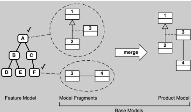
2. a merging approach where different models or fragments, each specifying a feature, are combined to obtain a complete product model from a feature model configuration (Figure 2). Our research question can be stated as follows: when specifying static properties of features and generating a product model from a configured fea-ture diagram, what are the challenges faced by the analyst using a merging approach?
The rest of this paper is organised as follows. In Section 2.1, we will give an overview of the techniques proposed in the literature for model pruning, and in Section 2.2 for model merging. In Section 3, our example and the experimental settings will be presented. In the following sec-tions, each identified challenge will be stated and discussed: The problem of synchronising different model fragments will be discussed in Section 4; the absence of variability notation in base models in Section 5; and the determination of the scope of a model fragment in Section 6. Requirements for better tool support will be suggested in Section 7. Section 8 will be devoted to a general discussion of our findings and future works will conclude this paper in Section 9.
2. Two generative approaches
2.1. Feature-based model pruning
Gottschalk et al. [6] favor a pruning approach to deal with dynamic aspects. They propose to
1 2 3 3 4 merge 1 2 3 4 A B C D E F ✓ ✓
Model Fragments Product Model Feature Model
Base Models
Figure 2. Merging of model fragments
configure domain models expressed by workflows (Petri nets). Their pruning algorithm comprises three steps: (1) removing elements that were not selected, (2) cleaning obsolete elements that are now disconnected, (3) check that every element is on a path from workflow input to output. Their ap-proach is however not specific to SPL and does not use feature models.
Czarnecki et al. [7] also use a pruning ap-proach. Each element of an activity diagram is annotated with a presence condition, expressed in terms of features. A FD is used to configure the activity diagram and a “flow analysis” ensures that each element is on a valid path and that the types of object flows are compatible. The same technique is used to configure the associated data model. Sch¨atz [8] proposes a similar although less general approach based on reactive components that com-bine a domain-specific model (automata, compo-nent diagrams and application-specific conceptual model) and a variability model.
2.2. Feature-based model merging
Sabetzadeh et al. [9] use model merging to detect structural inconsistencies. They transform a static model into a graph and then into a re-lational model, i.e., a textual description of the model. The consistency checks are expressed as a query on this relational model. Model merging is performed with the help of an interconnection dia-gram, which specifies semantic equivalence groups between model elements from different models. Traceability of model elements is kept along the
way, enabling to identify the origins of a detected inconsistency. In [10, 11, 12], the authors ad-dress dynamic models with behavioural matching as well. They provide algorithms and tool support to merge base models. Their work is not targeted on SPLE but, as we will see, is applicable here.
On the other hand, Perrouin et al. [13] specif-ically target SPLE. They propose to derive a prod-uct model by merging UML class diagram frag-ments. Their approach consists of two steps. First, given a feature model, a set of core assets and com-position constraints, they merge model elements (e.g., classes) based on signature matching. The signature of a model element is defined as a set of syntactic properties for the element type, and can be reduced to its name. Second, the merged model can be customised to support additional fea-tures that were not included in the product family.
3. Testing Perrouin et al. merging approach
The experiment presented here followed the merging approach by Perrouin et al. [13]. The latter was chosen because it is integrated, model-driven and focused on SPLE. This experiment con-stitutes a first step towards comparison of the prun-ing and mergprun-ing approaches, and further devel-opment and improvement of those. The chosen approach do not propose a specific merging al-gorithm and was complemented with the merging techniques of Sabetzadeh et al. [9].
3.1. The Conference Management System ex-ample
Through the rest of the paper we will use the example of a conference management system (ConfMS). A ConfMS is a software system that as-sists the Organising Committee of a scientific con-ference in the different phases of the concon-ference or-ganisation: publicise conference information like the Call for Papers, manage the submission and the review of the papers, organise the conference event locally, (i.e. the schedule, the sessions, the rooms), and publish the proceedings.
The IEEE [14] defines a conference as a “ma-jor meeting which covers a specialised (vertical) or broad range (horizontal) set of topics (...) The
pro-gram of a conference is designed to provide max-imum opportunity for presentation of high quality papers appropriate to the defined scope of the con-ference. To this end, a Call for Papers is issued to attract the most qualified presenters possible. Psentations are accepted after appropriate peer re-view.”
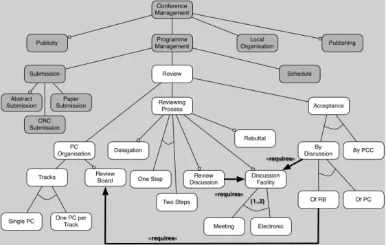
The authors’ knowledge of the ConfMS do-main comes from another experiment meant to select and evaluate software [15], leading to the construction of several domain models. Figure 3 presents a feature diagram of such a ConfMS. The constructions used in this diagram are: features (rounded boxes), the usual and-decomposition (edges), optional nodes (hollow circles), xor-decomposition (edges with an arc), a requires con-straint (thick arrow) and cardinalities (between curly braces). The features in white concern the review phase of conference organisation, we will specify them with a class diagram and obtain mod-els for different products using the merging tech-nique of Sabetzadeh et al. presented in section 2.2. The PC Organisation feature represents the hierarchical layout of the programme committee (PC): the presence of a single PC or of multiple PCs (Single PC or One PC per Track) and the pres-ence of a Review Board (RB) that oversees the work of the PC. The Reviewing Process feature de-scribes how the different reviewing steps are laid out in sequence (One Step or Two Steps), if review-ers can delegate their reviews to othreview-ers (Delega-tion) or if authors can comment the reviews (Rebut-tal). The Review Discussion feature represents the possibility for reviewers to discuss the papers. The Discussion Mediumfeature represents the different means of discussion (by Meeting or via Electronic forum). The Acceptance feature represents the ac-ceptance decision process for each paper. The list of accepted papers can be decided after discussion (By Discussion) by the PC (Of PC) or by the RB (Of RB), or by the Programme Chair alone (By PCC).
3.2. The experimental settings
The experiment was conducted by the two first authors, both PhD students who are
knowledge-Conference Management
Publicity ManagementProgramme OrganisationLocal Publishing
Submission Review Schedule
Abstract Submission Paper Submission PC Organisation Reviewing Process Review Discussion Acceptance Review Board Tracks
Single PC One PC per Track
Delegation One Step Two Steps Rebuttal Discussion Facility By PCC Of PC Of RB Meeting Electronic By Discussion {1..2} «requires» CRC Submission «requires» «requires»
Figure 3. Conference Management System Feature Diagram
able in UML and feature modelling techniques, during ten eight-hour working days, using only an erasable white board, pens, generic diagramming tools (Poseidon for UML and OmniGraffle) and coffee.
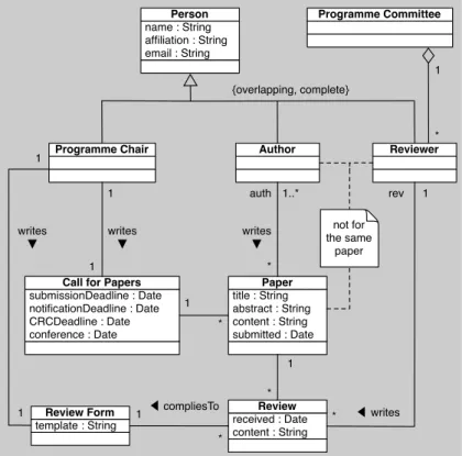
The authors wrote the base class diagram pre-sented in Figure 4, which models the commonal-ities of all the products of the feature diagram of Figure 3. They then wrote a class diagram frag-ment to model each sub-feature of the Review fea-ture. The base diagram was completed iteratively by detecting the common model elements in every model fragment.
Although the general framework of Perrouin et al.[13] was followed, the merging algorithm it-self used to generate these diagrams was executed manually and based on syntactic name matching inspired by Sabetzadeh et al. [9]. Equivalence groups between model elements are easier to deter-mine in the experimental settings, instead of writ-ing transformations inside Perrouin et al. [13] tool, and gives greater flexibility to test different solu-tions.
The first product generated by merging model fragments P1= {Review; PC Organisation; Tracks;
Single PC; Reviewing Process; One Step; Accep-tance; By PCC} suits a small conference or a work-shop, where there is a single PC and the acceptance decision is taken by the Programme Chair.
The second product P2= {Review; PC
Organ-isation; Tracks; Single PC; Review Board; Review-ing Process; Delegation; One Step; Rebuttal; Re-view Discussion; Discussion Medium; Electronic; Meeting; Acceptance; By Discussion; Of RB} suits a bigger conference where a Review Board super-vises the reviewing of the PC and the decision is taken by this Review Board. The software should provide electronic and live meeting discussion fa-cilities and allow review delegation.
Several challenges surfaced from this experi-ment, both during domain modelling and during the product model generation. In the next sections, we will detail three of them. Each is illustrated by the problems we faced during the experiment. Each of the following sections is subdivided as fol-lows: firstly, the context in which a challenge ap-pears is explained; secondly, we give specific in-stances encountered during the experiment, how we tried to overcome the problem and what are the alternatives available in the state of the art; finally,
title : String abstract : String content : String submitted : Date Paper Reviewer 1..* * name : String affiliation : String email : String Person Author Programme Chair {overlapping, complete} writes ▼ auth received : Date content : String Review * 1 rev 1 ◀ writes * template : String Review Form submissionDeadline : Date notificationDeadline : Date CRCDeadline : Date conference : Date
Call for Papers writes ▼ 1 1 1 1 1 1 * * ◀ compliesTo writes ▼ Programme Committee * 1 not for the same paper
Figure 4. Base Class Diagram
we try to discuss the remaining issues and suggest improvements.
The order in which the challenges are pre-sented was chosen only to facilitate the reader’s comprehension and do not follow any order of im-portance or frequency. Those challenges were only selected among others because they had an impor-tant impact on the modelling process. Other chal-lenges will be discussed in Section 8.
4. Challenge 1: distributed modelling and the need for synchronisation
4.1. Context: diverging base models
A first model comprising only the common concepts of the ConfMS was drawn. Then each feature was modelled successively. For a larger ap-plication however, it is likely that several features will be modelled in parallel. Remarkably, in both cases, the modelling process imposes some syn-chronisation to update the base models (it is a case
of co-evolution of models). The use of a common terminology or, at least, a common understanding between the teams is therefore necessary. Espe-cially since models are coupled and features inter-act with each other, it is important to achieve some level of agreement to be able to successfully merge the model fragments.
4.2. An instance
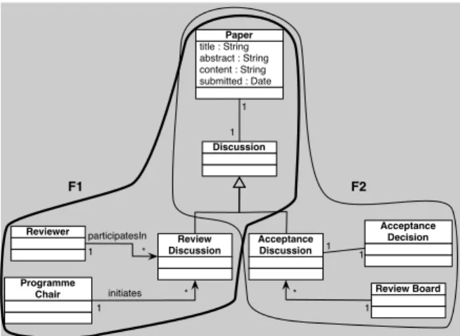
The two fragments (F1 and F2) made of a set of interrelated classes shown in Figure 5 describe two different types of discussion. The Review Dis-cussionfeature (F1) offers reviewers the possibil-ity to discuss the paper and their review. The By Discussion of Review Board feature (F2) offers to the Review Board the possibility to discuss the ac-ceptance decision of a paper.
F1 and F2 have a common part (F1T
F2) and differentparts F1 4 F2 = (F1 − F2)S
(F2 − F1). After merging the fragments, the resulting class di-agram contains the common parts (F1 T
F2) and the different parts (F1 4 F2). The latter are
asso-Review Board Acceptance Decision 1 1 * 1 title : String abstract : String content : String submitted : Date Paper Discussion Reviewer Programme Chair participatesIn initiates 1 * * 1 1 1 F2 F1
F1 = {Reviewer, Programme Chair, Paper, Discussion} F2 = {Acceptance Decision, Review Board, Paper, Discussion}
Figure 5. Merging of Two Features Class Dia-gram Fragment Review Board Acceptance Decision 1 1 * 1 title : String abstract : String content : String submitted : Date Paper Discussion Reviewer Programme Chair participatesIn initiates 1 * * 1 1 1 F2 F1 Acceptance Discussion Review Discussion
Figure 6. Merging of Two Features Class Dia-gram Fragment with class hierarchies
ciated to the common part. In this case, they are associated to the Discussion class.
The resulting class diagram is syntactically correct but it represents two very different situa-tions (namely two different kinds of discussion) as if they were the same. In order to avoid this kind of inconsistency, a decision of the analyst is neces-sary. One solution (Figure 6) is to use class special-isation and create a sub-class for each type of dis-cussion (Review Discussionand Acceptance Dis-cussion) that is associated to each different part, and a super-classDiscussion that is associated to the common parts.
4.3. Discussion
This is a modelling and a methodological prob-lem. We followed an iterative process. That is, we pushed common elements in fragments associ-ated to features higher in the feature tree when they were identified in several fragments. Conversely, we decided that common elements were shared down the feature tree following the feature decom-position relation in FDs. However, a single class can appear in several fragments. When it is con-currently modified, the status of the modifications is unclear. It can represent an undetected common-ality or require a refactoring in several fragments if the concepts are actually different. For example, the Discussion Facility feature was identified early on as a common feature, but when the two differ-ent types of discussion were later modelled, this feature had to decomposed and the fragments asso-ciated to three features had to be modified to avoid confusion during the merging operation if the two discussion features were selected.
One of the proposed solutions is to use an inte-grated meta-model that blends feature models and base models. It allows to support feature-aware modelling and change propagation, because each model element can be annotated with the feature to which it pertains. Bachmann et al. [16] have suggested an integrated meta-model that can better support this approach. Such model can also sim-plify the merging algorithm, as Brunet et al. [12] noted. The general problem of detecting common concepts between static models is not new, how-ever. It has been extensively studied in the case of database schema integration [17, 18]. It is also pos-sible to detect this problem earlier by performing a partial merge of model fragments, preferably auto-matically, in a way similar to Sabetzadeh et al. [9].
5. Challenge 2: when variability notation is necessary in base diagrams
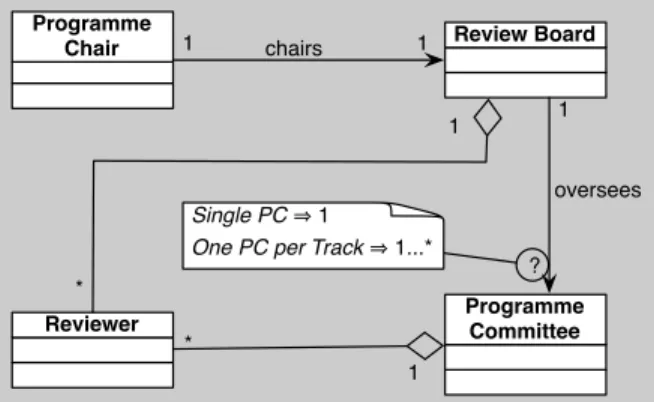
5.1. Context: variation points in base models A model fragment can be incomplete before the feature model is configured because some model elements depend on specific configuration,
Programme
Chair Review Board
Programme Committee Reviewer 1 1 1 * * 1 1 chairs oversees ? Single PC 1
One PC per Track 1...*
Figure 7. Review Board Class Diagram Frag-ment
i.e. the selection of certain features. Therefore, variability has to be explicitly modelled in base models, to be later resolved when the product model is generated by merging. More generally, some design decisions cannot be made a priori but the information is known when a specific product is built.
5.2. An instance
For example, the fragment associated with the Review Board feature is represented in Figure 7. We had to annotate it because a multiplicity was undefined. The multiplicity of the association oversees between the classes Review Board and
Programme Committeecan vary. This is because it depends on the selection of another feature: one of the two mutually exclusive decompositions of the Tracksfeature.
5.3. Discussion
Some variability notation is necessary to in-dicate a decision point in the model, particularly when modelling an optional feature. UML is eas-ily extensible and such information can be repre-sented by UML comments. However, this solu-tion seems to be impractical when the size of the product family increases. The major requirement is for this variability notation to be easily stored, retrieved and interpreted by software during mod-elling and merging. Several authors have identified this problem.
Pohl et al. [2] do not propose a general
tech-nique but use ad-hoc textual or graphical nota-tions when necessary. Gomaa [19] uses UML stereotypes and parameters to annotate common el-ements and variability in diagrams. Those tech-niques are not specific to the approach studied here and are not formally defined to enable automation. Czarnecki et al. [7] propose an elegant solution: to attach to certain base model elements a formally defined presence condition expressed in terms of features (selected or not). This approach scatters product family variability information throughout the fragments and risks to defeat the purpose of a separate feature model, although this risk can be mitigated by a good visualisation tool.
6. Challenge 3: to what feature does a frag-ment belong?
6.1. Context: identification of atomic sets When modelling a particular feature, the ques-tion of what is exactly modelled surfaces fre-quently. A specific feature with a well defined boundary within the system is easy, but other fea-tures are more cross-cutting by nature and the exact impact on the overall system is harder to define. In numerous occasions during the experiment, the au-thors wanted to be able to share a common model element between fragments, or modify a common element and specialise it. Other fragments were obviously associated to a set of features instead of a single one. Finally some features were more eas-ily modelled in conjunction with others.
6.2. Instance
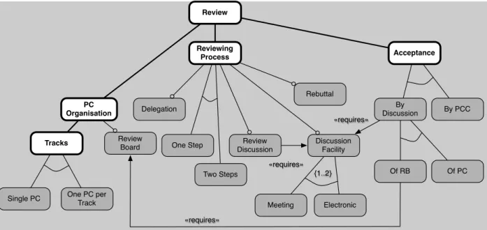
When a commonality is identified between features that represent a decomposition of a parent feature, the common elements were “pushed up” in the feature tree in the parent feature model frag-ment. An atomic set [20, 21] is a set of features that always appear together in a product. For example, in Figure 8 the atomic set composed of Review, PC Organisation, Tracks, Reviewing Process and Ac-ceptance is highlighted. It represents the core of the ConfMS application, so that when a common model element belongs to one of its features, it is in fact added to the model fragment associated with
the whole atomic set.
Another notable group of features in Figure 8 is related to the Discussion Facility feature. As seen in Section 4, it is easier to model it in conjunc-tion with the two features that require it. Although they do not form an atomic set, it is actually easier to include them in the scope of the model fragment associated with Discussion Facility.
6.3. Discussion
To alleviate this problem, and because the size of the domain model was moderate, we iteratively checked each completed fragment with the others, and tried to merge it to detect possible inconsis-tencies in advance. This solution, if not directly related to SPLE, was inspired by [9]. But the mod-elling of fragments also had an impact on the fea-ture model: the discovery of possible ambiguity led to the modification of the FD and to reconsider the commonality of the product line, such as with the Discussion feature. These questions are mainly methodological and, although related to other do-main modelling problems, specific to the merging approach. As far as we could observe, they are not yet covered in the literature. Concerning the merg-ing algorithm, if model fragments are associated to sets of features instead of individual features, it will decrease the computational complexity for this, as well as for other automations (e.g. genera-tion of all products or checking satisfiability).
7. Towards tool support
From the three challenges presented above, we can list several functionalities that would signifi-cantly improve the modelling of model fragments in a CASE tool supporting the approach: (1) an in-tegrated meta-model encompassing feature model and base models; (2) the possibility to associate variability information in the form of presence con-ditions (boolean expressions on features) to every model element; (3) the identification of atomic sets and common features; (4) the possibility to as-sociate model fragments to atomic sets and com-mon features; (5) the sharing of comcom-mon model elements in the relevant model fragments; (6) the
specialisation of common elements into feature-specific fragments; (7) conversely, the factorisation (up in the feature tree) of common model elements identified along the modelling process; (8) an ad-vanced visualisation engine that can selectively display the fragments associated to some features and the condition in which these fragments will ap-pear in a product.
Some functionalities would also improve the merging operation: (1) a formally defined and machine-readable presence condition language; (2) traceability information between features and model elements; (3) a partial merge algorithm to detect common model elements or possible merg-ing inconsistencies in advance.
8. General discussion
There are several threats to the validity of this study: the size of the example is moderate and some problems that would appear in bigger mod-els may not be noticeable here; the experiment was performed manually (except for generic dia-gramming tools) due to the lack of a proper inte-grated tool supporting the approach. Although the researchers who carried out the experiment were trained in modelling with FD and class diagrams, this was the first time they used those languages in an integrated fashion. Hence, some challenges might have been emphasised by their lack of ex-perience. However, such challenges would still be valuable to pinpoint because they highlight issues to be addressed when training new modellers to this integrated way of modelling. These challenges are likely to remain relevant for bigger products and families, due to the increased complexity of the modelling process execution (more products) and of the products themselves (more features).
The problems we have identified can be classi-fied in three categories: (1) semantic, (2) method-ological and (3) practical problems. The first cat-egory comes from the particular status of model fragments. They can express a limited amount of information, be incomplete, or even be syntac-tically incorrect and therefore, strictly speaking, meaningless but have an impact on the semantics of a product. The second category comes from
Review PC Organisation Reviewing Process Review Discussion Review Board Tracks
Single PC One PC per Track
Delegation One Step Two Steps Rebuttal Discussion Facility By PCC Of PC Of RB Meeting Electronic By Discussion {1..2} «requires» «requires» «requires» Acceptance
Figure 8. An atomic feature set in the Conference Management Set
the iterative and distributed nature of the process. Although feature modelling supports the separa-tion of concerns, some synchronisasepara-tion between the different model fragments is necessary from time to time, which requires to keep a view on the whole system and all of its variants, or locally on some set of features, which helps to inform par-ticular design decisions. Finally, better tool sup-port is necessary to ensure that the model frag-ments remain syntactically and semantically con-sistent with each other.
There are also advantages to such a merging approach. The ability to work on a subset of the features reduces the complexity of the problem, es-pecially if it is highly decomposable, that is when features are interacting through a small and pre-cisely defined interface. This approach can be par-tially supported by a tool. For static aspects, a simple name matching algorithm appears to cover most needs.
9. Conclusion & future works
We have reported three challenges that we faced during a modelling experiment. The first challenge was the lack of methodology to ease the co-evolution of model fragments, when common
model elements are identified and factored, or a new understanding of the domain requires to spe-cialise a common model element in different ways. The second challenge was the lack of variability notation in base models and the difficulty to sep-arate the variability information from the domain model. The third challenge was difficulty to define the scope of a model fragment, that is to determine what set of features it describes. From this exper-iment, requirements for a better tool support were suggested.
In the future, we intend to compare the merg-ing approach with the prunmerg-ing approach. We also want to extend this experiment to the dynamic (be-havioural) aspects of the base models. Finally, we hope to improve tool support by implementing the suggested functionalities and provide methodolog-ical guidelines.
Acknowledgements
The research reported here was partly funded by the MoVES Interuniversity Attraction Poles Programme, Belgium – Belgian Science Policy.
This work was also funded in part by the Ac-tions de Recherche Concert´ees - Minist`ere de la Communaut´e franc¸aise - Direction g´en´erale de
l’Enseignement non obligatoire et de la Recherche scientifique.
References
[1] P. C. Clements and L. Northrop, A Framework for Soft-ware Product Line Practice - Version 4.2. Pittsburgh, USA: Carnegie Mellon, Software Engineering Institute, 2003.
[2] K. Pohl, G. Bockle, and F. van der Linden, Software Product Line Engineering: Foundations, Principles and Techniques. Springer, July 2005.
[3] P.-Y. Schobbens, P. Heymans, and J.-C. Trigaux, “Fea-ture Diagrams: A Survey and a Formal Semantics,” in Proc. of the 14th IEEE International Requirements En-gineering Conference RE’06. Los Alamitos, CA, USA: IEEE Computer Society, 2006, pp. 136–145.
[4] J.-C. Trigaux, “Quality of feature diagram languages: Formal evaluation and comparison,” Ph.D. dissertation, University of Namur, Faculty of Computer Science, September 2008.
[5] A. G. Kleppe, J. Warmer, and W. Bast, MDA Explained: The Model Driven Architecture: Practice and Promise. Boston, MA, USA: Addison-Wesley Longman Publish-ing Co., Inc., 2003.
[6] F. Gottschalk, W. M. van der Aalst, M. H. Jansen-Vullers, and M. La Rosa, “Configurable workflow models,” International Journal of Co-operative Information Systems (IJCIS), vol. 17, no. 2, pp. 177–221, June 2008. [Online]. Avail-able: http://dx.doi.org/10.1142/S0218843008001798 [7] K. Czarnecki, “Mapping features to models: A
template approach based on superimposed variants,” in GPCE’05, volume 3676 of LNCS, 2005, pp. 422– 437. [Online]. Available: http://citeseerx.ist.psu.edu/ viewdoc/summary?doi=10.1.1.88.6127
[8] B. Sch¨atz, “Combining product lines and model-based development,” Electronic Notes in Theo-retical Computer Science, Jan 2007. [Online]. Available: http://linkinghub.elsevier.com/retrieve/pii/ S1571066107003933
[9] M. Sabetzadeh, S. Nejati, S. Liaskos, S. Easterbrook, and M. Chechik, “Consistency checking of concep-tual models via model merging,” in Requirements Engineering Conference, 2007. RE ’07. 15th IEEE International, 2007, pp. 221–230. [Online]. Available: http://dx.doi.org/10.1109/RE.2007.18
[10] M. Sabetzadeh, S. Nejati, S. Easterbrook, and M. Chechik, “A relationship-driven framework for model merging,” in MISE ’07: Proceedings of the Inter-national Workshop on Modeling in Software Engineer-ing. Washington, DC, USA: IEEE Computer Society, 2007, p. 2.
[11] S. Nejati, M. Sabetzadeh, M. Chechik, S. Easterbrook, and P. Zave, “Matching and merging of statecharts specifications,” in Proceedings of the 29th International Conference on Software Engineering, ICSE 2007, ser.
ICSE International Conference on Software Engineer-ing, AT&T Laboratories-Research, Florham Park, NJ, United States, 2007, pp. 54–63. [Online]. Available: http://dx.doi.org/10.1109/ICSE.2007.50
[12] G. Brunet, M. Chechik, S. Easterbrook, S. Nejati, N. Niu, and M. Sabetzadeh, “A manifesto for model merging,” in GaMMa ’06: Proceedings of the 2006 in-ternational workshop on Global integrated model man-agement. New York, NY, USA: ACM, 2006, pp. 5–12. [13] G. Perrouin, J. Klein, N. Guelfi, and J.-M. J´ez´equel, “Reconciling automation and flexibility in product derivation,” in Proceedings of the 12th International Software Product Line Conference SPLC ’08, 2008, pp. 339–348. [Online]. Available: http://dx.doi.org/10. 1109/SPLC.2008.38
[14] Institute of Electrical and Electronics Engineers, “IEEE Conferences Organization Manual,” last accessed July 2006. [Online]. Available: http://www.ieee.org/web/ conferences/mom/all manual.html
[15] G. Saval, P. Heymans, P.-Y. Schobbens, R. Matuleviˇcius, and J.-C. Trigaux, “Experimenting with the Selection of an Off-The-Shelf Conference Management System,” Poster presented at the 1st Intl. Workshop on Variabil-ity Modelling of Software-intensive Systems (VaMoS), January 2007.
[16] F. Bachmann, M. Goedicke, J. C. S. do Prado Leite, R. L. Nord, K. Pohl, B. Ramesh, and A. Vilbig, “A meta-model for representing variability in product fam-ily development.” in Software Product-Famfam-ily Engineer-ing, 5th Int’l Workshop, PFE 2003, Siena, Italy, Novem-ber 4-6, 2003, Revised Papers, ser. LNCS, vol. 3014. Springer, 2003, pp. 66–80.
[17] C. Batini, M. Lenzerini, and S. B. Navathe, “A compar-ative analysis of methodologies for database schema in-tegration,” ACM Comput. Surv., vol. 18, no. 4, pp. 323– 364, 1986.
[18] E. Rahm and P. A. Bernstein, “A survey of approaches to automatic schema matching,” The VLDB Journal, vol. 10, no. 4, pp. 334–350, 2001.
[19] H. Gomaa, Designing Software Product Lines
with UML: From Use Cases to
Pattern-Based Software Architectures (The Addison-Wesley Object Technology Series). Addison-Wesley Professional, July 2004. [Online]. Avail-able: http://www.amazon.ca/exec/obidos/redirect?tag= citeulike09-20\&path=ASIN/0201775956 [20] S. Segura, “Automated analysis of feature models using
atomic sets,” in Proceedings of the First Workshop on Analyses of Software Product Lines ASPL, 2008.
[21] W. Zhang, H. Zhao, and H. Mei, “A
propo-sitional logic-based method for verification of feature models,” in Formal Methods and Soft-ware Engineering. Springer Berlin / Heidelberg, 2004, pp. 115–130. [Online]. Available: http: //www.springerlink.com/content/fn47t2dwe26d3d3b