HAL Id: hal-00843324
https://hal.archives-ouvertes.fr/hal-00843324
Submitted on 11 Jul 2013
HAL is a multi-disciplinary open access
archive for the deposit and dissemination of
sci-entific research documents, whether they are
pub-lished or not. The documents may come from
teaching and research institutions in France or
abroad, or from public or private research centers.
L’archive ouverte pluridisciplinaire HAL, est
destinée au dépôt et à la diffusion de documents
scientifiques de niveau recherche, publiés ou non,
émanant des établissements d’enseignement et de
recherche français ou étrangers, des laboratoires
publics ou privés.
Model-based (Mechanical) Product Design
Mehdi Iraqi, Mathias Kleiner, Lionel Roucoules
To cite this version:
Mehdi Iraqi, Mathias Kleiner, Lionel Roucoules. Model-based (Mechanical) Product Design.
MOD-ELS 2011: 14th International Conference on Model Driven Engineering Languages and Systems, Oct
2011, New Zealand. pp.548-562, �10.1007/978-3-642-24485-8_40�. �hal-00843324�
Model-based (Mechanical) Product Design
Mehdi Iraqi1, Mathias Kleiner1, and Lionel Roucoules1
Arts et M´etiers ParisTech ; CNRS, LSIS, 2 cours des Arts et M´etiers, 13697
Aix-en-Provence, France
{mehdi.iraqi, mathias.kleiner, lionel.roucoules}@ensam.eu
Abstract. Mechanical product engineering is a research and industrial activity which studies the design of complex mechanical systems. The process, which involves the collaboration of various experts using domain-specific software, raises syntactic and semantic interoperability issues which are not addressed by existing software solutions or their underly-ing concepts. This article proposes a flexible model-based software archi-tecture that allows for a federation of experts to define and collaborate in innovative design processes. The presented generic approach is backed and validated by its implementation on an academic usecase.
1
Introduction
(Mechanical) product engineering is a domain which studies the entire lifecycle of a complex mechanical system from the customer requirements analysis to its end of life. It involves several phases: design, industrialisation, production, ex-ploitation, dismantling, recycling.
The design phase is the activity that aims at creating a complete digital mock-up including all information on the product coming from multiple points of view: functions, components, form features, materials, multi-physical behaviours, etc. [29, 27, 37]. This strongly knowledge-based and collaborative activity involves many partners with different expertises, each of them using very specialized computer tools, in their turn based on different knowledge representations and operational procedures.
Such a complex computer-assisted activity has to be supported by a flexible and efficient software architecture based on rigourous knowledge formalizations. Although it has been the subject of many research over the past 20 years, the current state-of-the-art suffers from many limitations such as lack of interoper-ability, lack of flexibility, lack of control over the manipulated knowledge, etc. This article first details these limitations as well as their associated challenges and requirements. We then propose a software architecture based-on model-driven engineering that aims at overcoming the current scientific and operational issues. The approach, called Model-driven product design, is backed by preceed-ing motivations studies [25, 1], operational, and validated through its application to an industrial product.
of product design, model-driven engineering main principles, as well as motiva-tions to this work through a study of current issues and challenges. Section 3 describes the approach and proposes a generic model-driven software architec-ture. In Section 4, we show its application to a product design scenario. Finally, Section 5, discusses related work and proposes directions for future research.
2
Context
2.1 Introduction to (mechanical) product design
Mechanical product design is part of mechanical product engineering that aims at studying a product from its beginning of life (marketing, value analysis...) to its end of life (dismantling, recycling...). This approach strongly supports the design rational information that assists industry both in innovative or routine product design. Product design has to tackle the path from functions (what the product is designed for) and solutions (what are the technologies to achieve functions). The design process is commonly composed of several phases [15]: requirements specification, conceptual design, embodiment design and detailed design that progressively breakdown the product in multiple bill of material (BOM): defined (F-BOM), designed (Product-BOM, CAD-BOM...), as-manufactured (CAM-BOM...). In the current industrial context of the extended enterprise, the design activity is composed of collaborative and remote tasks that need to link all the knowledge coming from different experts that define their own BOM (functional analysis, components and material selection, structure analysis, manufacturing process selection...). Nowadays most of those BOM are computer-supported, three main categories can be listed:
– The PLM (Product LifeCycle Management) system which acts as the infor-mation backbone and that should link every BOM [3]. However, these tools operate at a low-granularity level. Indeed, they mainly consist in a database of files produced by different expert tools (CAD or CAx), with some ad-ditional workflow management (files repositories with dependencies, access restrictions and versioning). As such, they do not provide detailed knowl-edge management and rely on existing file exchange standards to achieve interoperability.
– The CAx (Computer Aided X) tools that support product’s X assessments during the design process (X is then related to functional analysis, manufac-turability analysis, recycling analysis...).
– The CAD (Computer Aided Design) software that manages form features and acts as one of the collaborative space for designers since the design pro-cess is still CAD-centric. Some of CAD tools have been extended over the years to embrace the increasing collaborative aspect of engineering. A per-fect example of this approach is the leading CAO tool CATIA [34]. Based on engineering good practices, they have developed additional modules which plug different expertises to the geometrical representation of the product. For instance, a facility allows to run simple simulations directly. Lately, they
have also included workflow capabilities (such as files shared repository and access restrictions). Limits of such an approach are well known by software developers: lack of modularity (ad hoc integration), lack of functionalities (modules are less powerful than specialized tools), lack of efficiency (engi-neers have to adapt their practices to the tool, when it should be the software that adapts to the user).
2.2 Introduction to MDE and model transformation
Model Driven Engineering considers models, through multiple abstract repre-sentation levels, as a unifying software concept. The central notions that have been introduced are terminal model, metamodel, and metametamodel. A ter-minal model is a representation of a system. It captures some characteristics of the system and provides knowledge about it. MDE tools act on terminal models expressed in precise modeling languages. The abstract syntax of a modeling lan-guage, when expressed as a model, is called a metamodel. The relation between a model and the metamodel of its language is called conformsTo. Metamodels are in turn expressed in a modeling language for which conceptual foundations are captured in an auto-descriptive model called metametamodel. This metameta-model language, derived from set-theory and object-languages, usually consists of entities, attributes and relations.
While this originates from an industrial need to have a homogeneous orga-nization where different facets of a software system may be easily separated or combined, the proposed architecture goes beyond software or platform models and reveals itself suited for many other areas where knowledge representation, exchange and reasoning is a central preoccupation, including ontologies [31].
The main way to automate MDE is by executing operations on models. For instance, the production of a model M b from a model M a by a transformation M t is called a model transformation. The OMG’s Query View Transform (QVT) specification[26] defines a set of useful model operations, an appropriate descrip-tive language, and proposes clues on how it should be implemented.
Finally, interoperability with non-MDE enabled technologies (here called tech-nical spaces) is achieved by special projections here called injection (obtaining a model from structured data) and extraction (the opposite operation).
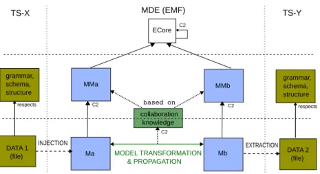
These main MDE principles and technologies are summarized in Figure 1.
2.3 Current issues and challenges in product design software
In order to support the product design activity, the information system is now recognized as a critical component of collaborative engineering practices [6]. Sub-section 2.1 has presented the main categories of current computer tools currently used in industry to support mechanical product modelling. Although those tools have reached a high level of functionalities several issues remais to fully tackle the real complexity of design process. For 15 years the paradigm of design activ-ity has changed from a sequential process to a concurrent process [30]. Since the design solution is not selected by a unique person any more, this new paradigm
ECore C2 MDE (EMF) MMa grammar, schema, structure Ma DATA 1 (file) respects C2 EXTRACTION MMb Mb C2 MODEL TRANSFORMATION & PROPAGATION INJECTION collaboration knowledge based on C2 TS-Y TS-X grammar, schema, structure DATA 2 (file) respects
Fig. 1. Model-driven engineering main principles
increased the involvement of several experts in the solution selection. The design process has then to be centred on experts knowledge. New issues are then related to the complexity of managing that knowledge via computer-supported tools: Knowledge synthesis versus form feature modelling For almost 30 years CAD systems have been developed and improved to currently reach very powerful features to support product’s shape modelling. They are actually presented and used as one of the central systems that make the design process a geometric cen-tric approach. This approach has shown its great interest in industry to tackle the problem of digitizing hand-done drawing, to improve the CAD-CAM links. Nowadays, the CAD model also finds an interest to improve the digital mock-up used during a decision making process. However current CAD systems are not able to manage all the knowledge related to the product definition. This information as mentioned in [9] has to be related to the whole lifecycle (from re-quirement specifications to dismantling information). The product, and its CAD model, is then defined, as far as possible, taken into account “X” constraints as assumed in a DFX (Design For X) approach. CAD model (i.e. form feature) has then to be generated from knowledge synthesis approach [24] seen as knowledge transformation in the proposed MDE environment.
Interoperability face to heterogeneity of knowledge modelling Since the number of experts and product assessments are increasing, information (i.e. knowledge) is becoming more and more heterogeneous but have to be linked in order to manage the impact of one on each other. Each knowledge model is indeed created and can evolve independently of each other. [17] proposes three approaches to afford the interoperability (i.e. link) of that heterogeneous knowledge. Due to the limitation of each approach the proposed MDE architecture is based on a federation solution using transformation concept in order to link each BOM as proposed in [13]:
– Integration that aims at proposing a unique global fused model that integrate every knowledge concepts. A consensus has to be found among every concept, and should be changed if a new concept is added.
– Unification that aims at proposing a meta-model used to map each knowl-edge concept via semantic association. The meta-model has to evolve or a new one has to be created if a new concept is added.
– Federation that aims at creating mappings between each knowledge concepts dynamically. This approach seems to be the more flexible one since only local changes have to be treated when adding new knowledge concepts. The dynamic creation remains nevertheless a great difficulty and will not be fully treated in this paper.
3
A Model-based software architecture for product
design
As seen previously, we believe MDE is fitted to support a product design soft-ware architecture. In order to map MDE concepts and operations to product engineering, we have compiled design scenarios from academic litterature and industrial usescases. As a result, we identified a set of different concepts, limita-tions and requirements. We first give an overview of the proposed architecture, then discuss its different parts and alternatives in details.
3.1 Architecture overview
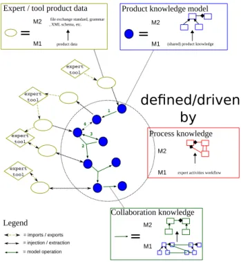
Figure 2 presents an overview of the proposed software architecture, illustrated through a fictive scenario involving various components. As outlined by the squares on the side, the symbols may be read equally at two levels with dif-ferent semantics, corresponding to the M1 and M2 levels of MDE:
– Yellow ellipses represent expert tools data. At level M2, their data structure or grammar. At level M1, the actual file produced (i.e. exported) or used (i.e. imported) by a specialized tool.
– At both levels, the dotted circle represents the frontier between tools techni-cal spaces and MDE. The dotted arrows represent the injections/extractions required to obtain corresponding knowledge models.
– At a level M2 lecture, blue-filled circles represent the domain-specific meta-models, whereas at level M1 they are the actual models manipulated during the scenario.
– Green solid arrows represent (inter-)model operations. At level M2, it is their definition (hopefully a declarative description). At level M1, their execution on the models during the scenario. The different types of operations needed (marked by numbers on the figure) are detailed in a following subsection. – The whole process is defined and driven by design process knowledge,
= injection / extraction
Product knowledge model
expert tool
Expert / tool product data
file exchange standard, grammar , XML schema, etc.
=
M1 = imports / exports M2 product data=
M1 M2(shared) product knowledge
Legend Collaboration knowledge
=
M1 M2defined/driven
by
Process knowledge M1 M2expert activities workflow 1 2 3 4 = model operation expert tool expert tool expert tool
Fig. 2. Architecture overview
3.2 Technical spaces and connectors
Expert tools use various formats to store and manipulate data. Most, if not all, provide import/export facilities from/to either proprietary formats, or, for inter-operability requirements, from/to industry standards (in our industrial context, STEP [32] is largely used). In order to manipulate product data in the MDE environment, we need to obtain corresponding knowledge models.
This operation, here called injection/extraction, has a well-known process in the MDE community: 1) obtain, or define, the data structure of the technical space; 2) define the corresponding metamodel; 3) map both of them using a MDE lan-guage/tool that automates the operation.
In practice, we usually fall into two main possibilities:
– An XML format is provided: the process is then eased by existing work on briding XML schemas to metamodels.
– A textual file is provided: a grammar of the textual syntax has to be defined (usually in EBNF style), and its concepts mapped to the metamodel. The obtained metamodel is often syntactically close to the original data struc-ture. However, it is possible to complete the connector with an additional trans-formation, defining (or reusing) a target metamodel that has a more appropriate structure.
Finally, it is important to note that not all the data manipulated by the expert tool may be of relevance for collaborating with other experts. In that sense, the model-based architecture offers a very flexible approach: the knowledge model can very well be a (reformulated) subset of the original expert data.
In the implementation and usecase sections, we will show the application of these alternatives on a concrete scenario and discuss potential fallbacks.
3.3 Knowledge (meta)models
Knowledge metamodels capture a subset of expert data that is relevant for other experts in the design scenario. The architecture does not place any constraint on which metamodels should be used, hence remaining flexible. However, our experience shows that we are mainly dealing with three types of knowledge models:
– Tool models. These counterparts of expert tools data structure, as seen in the previous subsection, may be used as entry-point models to obtain specialized (tool-independant) models, or simply linked to another tool model in order to achieve interoperability.
– Specialized models. Design scenarios litterature describe custom knowledge models which aim at defining, checking or enforcing specific properties of the product (such as its energetic integrity).
– Intermediate models. Complex transformations may require intermediate models for technical (simplicity) or conceptual reasons (semantic decom-position).
The flexibility of the approach allows for an easier development of new design scenarios: knowledge models may be reused, extended or created from scratch depending on the scientific analysis rather than tools existing support. Possibil-ities are however limited by the expressiveness of the metametamodel language.
3.4 Model operations
From the studied scenarios, we outline a (non-exhaustive) list of different experts collaboration patterns, translate them to knowledge manipulation requirements, and map these to existing MDE concepts and technologies:
– The output of an expert is used, later in the design process, by another expert. This is a typical interoperability problem. To obtain the downstream knowledge model, existing rule-based model transformation technics [18, 7] can be used (mark 1 on Fig 2).
– The output of several expert analysis have to be combined. A classical exam-ple is the geometrical mockup of the designed product, which is constrained by several expert analysis (energy flows, materials, technologies, etc.). In order to merge (and/or divide) knowledge, modern MDE tools offer the pos-sibility to specify multi-source (and/or multi-target) transformations (mark 2 on Fig 2).
– Two (or more) experts share some knowledge and have to maintain their data consistent. Typically, different analysis will share product parameters. When activities are held in a back and forth stream, bijective transforma-tions may be used. Since these transformatransforma-tions are not yet mature [33], MDE applications usually simulate this behaviour with two injective transforma-tions. When activities are held concurrently, more advanced mechanisms, such as constraint-based propagation of modifications [4], are to be investi-gated (mark 3 on Fig 2).
– An expert is faced with two or more inconsistent data constraints. It is thus required to calculate the impact of modifications and notify upstream experts. Although a rough impact can be calculated from the activities work-flow, the MDE approach may offer more fine-grained possibilities through traceability mechanisms [16]. As the production of knowledge may be achieved through an external tool operation, traceability must also be kept between the models which are not directly transformed (mark 4 on Fig 2).
3.5 Process (meta)model
A design scenario is supported by a process which describes the different experts, activities and tools involved, as well as temporal and collaboration constraints. This description may be captured using existing generic workflow languages or product engineering specialized languages [14].
The MDE process, which describes the models and model operations involved, can be automatically derived from the expert activities workflow.
These are however out of scope of this paper which does not preclude or impose the use of a particular process language.
4
Usecase
In order to further validate the presented architecture, we illustrate its use on an innovative design scenario which is not currently well supported by existing software solutions. The usecase, adapted from [19], deals with the design of a mechanical coupling system between a plane propeller and a diesel engine. The design process aims at obtaining a description of a product assembly from its functional and energetic analysis.
Figure 3 outlines the tools, data files and knowledge models used in the scenario. The following subsections detail each operation.
4.1 Architecture implementation
We have chosen the Eclipse EMF platform [8] as the implementation framework, mainly for its maturity and tools support. ECORE is used as the metametamodel language. The usecase files, models and transformations are open source and can be freely downloaded from a single package [5]. In the following, metamodels will be represented using ECORE diagrams.
TDC System CATIA FPPT
SK2
ASB
TDC data CATIA data
Fig. 3. Usecase scenario
4.2 Knowledge models
Our scenario uses three specialized models which are briefly introduced below.
FPPT FPPT stands for Function, Physical Principle, Technology. Informally described in [21], we created a metamodel which covers most of its concepts. An excerpt is shown in Figure 4. Functions refer to abstract product functionalities, which may be divided into subfunctions. Terminal functions are realized, through a physical principle, by a specific (known) technology.
PhysicalPrincip type : physicalPrincipType formula : EString physicalLimit : EFloat scaleLimit : EFloat loss : EString unit : EString Technology type : technologyType scaleLimit : EString physicalLimit : EString Parameter name : EString infLimit : EFloat supLimit : EFloat nominal : EFloat Function name : EString loss : EBoolean Part ID : EInt name : EString TechnologyParameter PhysicalPrincipParameter FunctionParameter physicalParameter1..* sFunction 0..* technology0..* technologyParameter1..* sFunction 0..* parameterFunction1..* physicalPrincip 0..* sFunction 0..* input1 output1 function 1..2
SK2 SK2 stands for Skins, Skeletons, informally described in [23]. Figure 5 is an excerpt of the corresponding metamodel. Briefly, product parts have external skins which can be linked to other skins. The product skeleton, which represents the energy flows, is made of external functions between those skins, and internal functions inside the parts. Each function has energetic properties.
Function name : EString principType : principType InternalFunction ExternalFunction functionType : functionType Skeleton ID : EString skeletonDirection : skeletonDirection InternalSkeleton ExternalSkeleton Part ID : EInt Materiau : EString name : EString Skin ID : EString formEntity : EString tolerance : EString rugosity : EString matiereDirection : EString System name : EString part 1 internalSkeleton 1..* externalSkeleton 2 input 1 output 1 skin 1 externalFunction 1 skin 1 skin 1..* internalFunction 1 function 1..2 part 1 internalSkeleton1 externalSkeleton 1 part 1..* function 1..*
Fig. 5. An excerpt of the SK2 metamodel
ASB ASB stands for product ASemBly. This very simple metamodel, in which the system is simply viewed as a set of interconnected parts, has been created specifically for this scenario, as an intermediate knowledge model between SK2 and the CAD tool CATIA.
4.3 TDC - FPPT connector
The functional analysis tool selected for the usecase is TDC [35]. The tool pro-vides an export of its data as an XML file. We used EMF native facilities to ob-tain the ECORE metamodel from the provided XML schema and the associated injection/extraction operation. However, due to XML arborescent restrictions, the associative references of the schema are simulated through the equivalence of textual properties (IDs). We thus created an additional model transformation, using ATL, to a target metamodel where associative references are restored. The final step to the connector is an ATL transformation which targets the FPPT metamodel. The transformation involves a loss of knowledge which is not relevant for other experts in the context of our collaborative scenario.
Figure 6 summarizes this chain of transformations.
4.4 FPPT to SK2 transformation
ECore C2 MDE (EMF) TDC-tree metamodel TDC XML schema Ma TDC data respects C2 Mb C2 ATL EMF TS-XML XML FPPT metamodel Mc C2 TDC-graph metamodel injection extraction ATL C2 respects
Fig. 6. TDC - FPPT : chain of transformations
– a mapping from FPPT’s functions and technologies to SK2’s external func-tions and parts.
– a characterization of the skeleton energetic properties obtained from FPPT’s physical principles.
4.5 SK2 to ASB transformation
This very simple ATL transformation uses SK2’s knowledge to create an assem-bly where different product parts are linked according to the skeleton.
4.6 ASB to CATIA connector
The selected geometrical modelling tool is CATIA [34]. Among the possible for-mats for importing data, CATIA proposes the use of STEP AP-203 [11], an industry standard for exchanging geometrical information about a mechanical product.
The STEP standard [32] defines textual files which conform to a STEP schema (Application Protocol here AP-203), which in turn is defined using a relational language called EXPRESS [10]. The OMG had already considered the interop-erability between STEP files and MOF models in the original XMI proposal. Two alternatives were envisionned:
– a metametamodel mapping between EXPRESS and MOF, if any is possible due to the semantic gap.
– a metamodel mapping between a specific STEP schema and its counterpart metamodel.
To the best of our knowledge, the first option has been worked on by various projects but is not yet mature nor known feasible in the general case. We thus choosed the second option.
Technically, we used XTEXT/XPAND [38] to define the STEP grammar and generated the corresponding metamodel. This state-of-the-art technology allows us to inject and extract STEP files to/from STEP models.
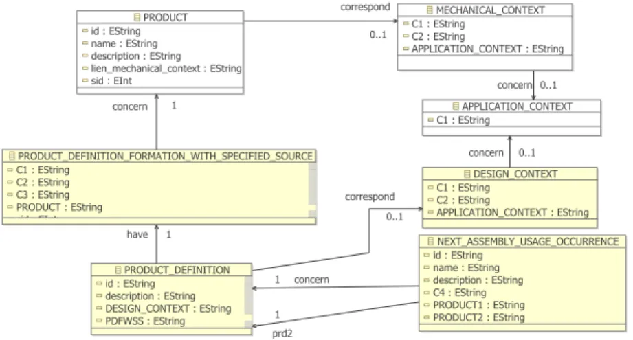
For the sake of clarity, we separated the STEP general metamodel from the AP-203 schema metamodel (which contains most fo the product information). An excerpt of the latter is shown in Figure 7.
A first ATL transformation generates an AP-203 model from our assembly
Fig. 7. excerpt of the STEP AP-203 metamodel
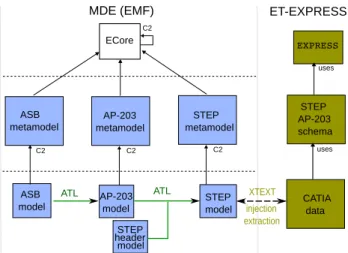
knowledge model (ASB). In order to obtain the general STEP model, a second ATL transformation takes two models as source: the AP-203 model and a custom model which only contains necessary header information for the STEP file (such as document creator, date, etc.). Figure 8 shows the whole connector chain of transformations.
5
Related and future work
From the product engineering perspective, most of the related work has been car-ried out using integrated product model approaches [27], often supported by on-tology management technologies [20], as opposed to the model-based federation proposed in this article. Recent work have explored the use of meta-modelling [36], but are restricted to specific operations such as tool interoperability [22], de-sign coherency [28], or focus small parts of the dede-sign process such as functional requirements [20]. [12, 25] share our requirements for weavings and transforma-tions between federated product models but stay at a conceptual level. Our work generalizes these principles in an flexible federation approach grounded in model-based techniques.
ECore C2 MDE (EMF) ASB metamodel STEP AP-203 schema ASB
model CATIA data
uses C2 AP-203 model C2 ATL XTEXT ET-EXPRESS EXPRESS STEP metamodel STEP model C2 AP-203 metamodel injection extraction ATL uses STEP header model
Fig. 8. ASB - CATIA : chain of transformations
From the model-driven engineering perspective, product design requires complex metamodels and transformation processes. Therefore, while our work makes use of several existing model-based techniques, it also raises new challenges regarding traceability, consistency, bidirectional transformations and metamodels expres-siveness. A large share of the work on megamodels, for instance [2], may also be adapted to ease the definition and evolution of the design process.
Future work includes experimentations on various industrial usecases, in order to confirm the viability of the MDE architecture and propose generic methods for the different collaboration patterns. One of the critical issues is incremental change management and its propagation to upstream and downstream models. Finally, investigations are currently carried out to tackle the dynamic aspects presented in Subsection 2.3. The expected output is a design process model which will be used to generate and automate the software process.
6
Conclusion
We described in this article a model-based federation approach for the design of mechanical products. The proposed architecture adapts model techniques such as metamodelling, transformations and projections to the context of collabora-tive product design software. Based on previous experiences and studied design scenarios, generic and flexible model-based solutions are proposed to handle the digital chain of product knowledge. The implementation on an academic usecase shows the viability of the approach. Considering the high complexity and hetero-genity of product design scenarios, a number of original issues and challenges are raised, which lays the path for future investigations on both product engineering and model-based software techniques.
Acknowledgements This work has been partially funded by the french project ADN. The authors would like to thank S. Roger, who did his master study on some metamodels and model transformations for the usecase; as well as TDC Software, for their help in understanding the concepts of the TDC XML schema.
References
1. Etienne A., Guyot E., Cabannes G., Ducellier G., and Roucoules L. Specifica-tion and developments of interoperability soluSpecifica-tions dedicated to multiple expertise collaboration in a design framework. In International Conference on Software, Knowledge, Information Management and Applications, 2008.
2. Jean B´ezivin, Fr´ed´eric Jouault, Peter Rosenthal, and Patrick Valduriez. Modeling
in the large and modeling in the small. In Uwe Aßmann, Mehmet Aksit, and Arend Rensink, editors, Model Driven Architecture, volume 3599 of Lecture Notes in Computer Science, pages 901–901. Springer Berlin / Heidelberg, 2005.
3. PLM Market Growth in 2008, Mid-Year: http://www.cimdata.com, 2009.
4. K. Czarnecki and S. Helsen. Feature-based survey of model transformation ap-proaches. IBM Syst. J., 45:621–645, July 2006.
5. Delvion usecase: http://www.lsis.org/kleinerm/MPD/Delvion usecase.html, 2011. 6. Kadiri S. E., Pernelle P., Delattre M., , and Bouras A. Current situation of plm
systems in sme/smi : Survey’s results and analysis. In International Conference on Product Lifecycle Management, 2009.
7. K. Ehrig, E. Guerra, J., L. Lengyel, T. Levendovszky, U. Prange, G. Taentzer,
D. Varr´o, and S. Varr´o-Gyapay. Model transformation by graph transformation:
A comparative study. In MTiP 2005, International Workshop on Model Transfor-mations in Practice (Satellite Event of MoDELS 2005), 2005.
8. EMF : http://www.eclipse.org/modeling/emf/, 2009.
9. F.-L. Krause et al. Product modelling. CIRP Annals - Manufacturing Technology, 42(2):695 – 706, 1993.
10. ISO 10303-11, Industrial automation systems and integration – Product data rep-resentation and exchange - Part 11: The EXPRESS language reference, 1994. 11. ISO 10303-203, Industrial automation systems and integration – Product data
rep-resentation and exchange - Part 203: Configuration controlled 3D designs of me-chanical parts and assemblies, 1994.
12. Maier F., Mayer W., Stumptner M., and Muehlenfeld A. Ontology-based process modelling for design optimisation support. In Design Computing and Cognition ’08, pages 513–532. Springer Netherlands, 2008.
13. E. Frey, E. Ostrosi, L. Roucoules, and S. Gomes. Multi-domain product modelling: from requirements to cad and simulation tools. In International conference on engineering design, 2009.
14. Booch G., Rumbaugh J., and Jacobson I. Unified Modeling Language User Guide. Addison-Wesley Professional, 2005.
15. Pahl G., Beitz W., Feldhusen J., and Grote K.H. Engineering design : a systematic approach. Springer-Verlag, 6th edition, 1996.
16. Ismˆenia Galv˜ao and Arda Goknil. Survey of traceability approaches in
model-driven engineering. In EDOC, pages 313–326. IEEE Computer Society, 2007. 17. ISO 14258, Industrial Automation Systems - Concepts and Rules for Enterprise
18. Jouault J. and Kurtev I. Transforming Models with ATL. In MoDELS Satellite Events, volume 3844 of LNCS, pages 128–138. Springer, 2005.
19. Klein Meyer J.S. Mod´elisation multi-physique des syst`emes complexes dans un
contexte de DFX. Application `a la conception de micro-m´ecanismes. PhD thesis,
Universit´e de Technologie de Troyes, 2008.
20. Yoshinobu Kitamura, Sunao Takafuji, and Riichiro Mizoguchi. Towards a reference ontology for functional knowledge interoperability. ASME Conference Proceedings, 2007(48078):111–120, 2007.
21. J. Klein Meyer, L. Roucoules, A. Grave, and J. Chaput. Case study of a mems switch supported by a fbs and dfm framework. In The Future of Product Develop-ment, pages 377–386. Springer Berlin Heidelberg, 2007.
22. F.-L. Krause and U. Kaufmann. Meta-modelling for interoperability in product design. CIRP Annals - Manufacturing Technology, 56(1):159 – 162, 2007. 23. Roucoules L. and Skander A. Manufacturing process selection and integration in
product design. analysis and synthesis approaches. In CIRP Design seminar, 2003. 24. Roucoules L. and Lafon P. et al. Knowledge intensive approach towards multiple product modelling and geometry emergence to foster cooperative design. In CIRP Design seminar, 2006.
25. Arndt M¨uhlenfeld, Franz Maier, Wolfgang Mayer, and Markus Stumptner.
Mod-elling and management of design artefacts in design optimisation. In Collaborative Product and Service Life Cycle Management for a Sustainable World, Advanced Concurrent Engineering, pages 513–520. Springer London, 2008.
26. Object Management Group. Meta Object Facility (MOF) 2.0
Query/View/Transformation (QVT) Specification, version 1.0, 2008.
27. Tichkiewitch S. Specifications on integrated design methodology using a multi-view product model. In Biennial Joint Conference on Engineering Systems Design and Analysis, pages 101–108, 1996.
28. Mohsen Sadeghi, Fr´ed´eric Noel, and Khaled Hadj-Hamou. Development of
con-trol mechanisms to support coherency of product model during cooperative design process. Journal of Intelligent Manufacturing, 21:539–554, 2010.
29. J.J. Shah. Assessment of features technology. Computer-Aided Design, 23(5):331 – 343, 1991.
30. G. Sohlenius. Concurrent engineering. CIRP Annals - Manufacturing Technology, 41(2):645 – 655, 1992.
31. Steffen Staab, Tobias Walter, Gerd Gr¨oner, and Fernando Silva Parreiras. Model
driven engineering with ontology technologies. In Reasoning Web, volume 6325 of Lecture Notes in Computer Science, pages 62–98. Springer, 2010.
32. ISO 10303, Industrial automation systems and integration – Product data repre-sentation and exchange, 1994.
33. Perdita Stevens. Bidirectional model transformations in qvt: semantic issues and open questions. Software and System Modeling, 9(1):7–20, 2010.
34. CATIA (Dassault systems) - http://www.3ds.com/products/catia/welcome/, 2011. 35. TDC system - http://www.tdc.fr/en/products/tdc system.php, 2011.
36. G. Gary Wang and S. Shan. Review of metamodeling techniques in support of engineering design optimization. Mechanical Design, 129(4):370–380, 2007.
37. Yan X.-T. A multiple perspective product modeling and simulation approach
to engineering design support. Concurrent Engineering Research and Application Journal, 11(3):221–234, 2003.