HAL Id: hal-01829910
https://hal.archives-ouvertes.fr/hal-01829910
Submitted on 4 Jul 2018HAL is a multi-disciplinary open access archive for the deposit and dissemination of sci-entific research documents, whether they are pub-lished or not. The documents may come from teaching and research institutions in France or abroad, or from public or private research centers.
L’archive ouverte pluridisciplinaire HAL, est destinée au dépôt et à la diffusion de documents scientifiques de niveau recherche, publiés ou non, émanant des établissements d’enseignement et de recherche français ou étrangers, des laboratoires publics ou privés.
Property Model Methodology: A Landing Gear
Operational Use Case.
Patrice Micouin, Pascal Paper, Louis Fabre, Thomas Razafimahefa, Roland
Becquet, François Guérin
To cite this version:
Patrice Micouin, Pascal Paper, Louis Fabre, Thomas Razafimahefa, Roland Becquet, et al.. Property Model Methodology: A Landing Gear Operational Use Case.. INCOSE International Symposium 2018, Jul 2018, Washington DC, United States. �hal-01829910�
Property Model Methodology: A Landing Gear
Operational Use Case.
Patrice Micouin Micouin Consulting +33 (0)675938389 [email protected] Louis Fabre Airbus Helicopters +33 (0)633471659 [email protected] Roland Becquet Airbus Helicopters +33 (0)442852925 [email protected] Pascal Paper Airbus Helicopters +33 (0)609267958 [email protected] Thomas Razafimahefa Airbus Helicopters +33 (0)442852572 [email protected] François Guérin MathWorks Company +33 (0)141148861 [email protected]
Copyright © 2018 by Patrice Micouin, Pascal Paper, Louis Fabre, Thomas Razafimahefa, Roland Becquet and François Guérin. Published and used by INCOSE with permission.
Abstract. Relevant for engineering a wide range of technological systems, Property Model Methodology (PMM) is applied in this paper to the development process of a helicopter function in the frame of the ARP4754A/ED79A. After a short presentation of the method, the case study is presented: "to retract and to extend airborne the landing gear system". Then, each stage of the PMM development process is illustrated by examples from the case study: (1) Modeling the top level requirements specification, (2) Validating the requirements specification by proof and simulation, (3) Modeling the architectural design, Refining the top level requirements into requirements specified to the different subsystems contributing to the function and Modeling the terminal subsystems detailed designs (4) Validating the requirements specified to the contributing subsystems by proof or simulation, (5) Verifying the design models by simulation and finally (6-8) Verifying physical implementations by test on the basis of all validation and verification scenarios accumulated throughout the development. At end, lessons learnt and industrial perspectives are summarized highlighting how PMM is a methodology adapted to the challenges facing to systems engineering by the globalization of development processes and showing how PMM can provide a powerful conceptual framework to support digital continuity within globalized Design Organizations. Modeling, simulation, proof and test generation activities are supported by the MATLAB and Simulink products.
Introduction
The aeronautic industry has to deliver more and more complicated systems in term of functions while maintaining high level of quality and safety/reliability. In the same time, competition is driving aircraft manufacturers to strongly improve their costs (including non-recurring costs) and development lead time. At the age of globalization, these systems are designed and produced by large, multicultural, geographically distributed teams belonging to different industrial organizations. This evolution introduces additional complexities (the complexity of a goal-oriented process refers to its propensity to fail [Suh, 2005]). To face these challenges, classical systems engineering approaches
do not provide a sufficient level of efficiency when a huge amount of disparate documents are to be produced, exchanged and used by stakeholders, before being able to reach the expected level of maturity to develop a product. Providing and sharing quickly unambiguous and validated specifications, verified designs and interface descriptions, validation and verification scenarios becomes a key issue to ensure an efficient and safe workflow and a digital continuity between all the stakeholders.
In this paper, the authors synthesize the results of a helicopter function development carried out during the first six months of 2017 at the Airbus Helicopters Design Office. After a brief presentation of the PMM methodology, we provide the reader with descriptions of the applicative context and the H/C (H/C stands for helicopter) function selected as use case. Then, we describe the development sequence by distinguishing at each step the two following levels: (1) PMM methodological guides and (2) Implementation in the MATLAB and Simulink products modeling and simulation environment. Lastly, we summarize the main lessons learnt in this experiment and we identify the way ahead from an industrial point of views. Note that some technical points such as the integration of concurrent modeling activities, physical interfaces derivation from functional interfaces and safety topics are not reported in the frame of this size-limited paper.
PMM process and core concept overview
PMM is a Model-Based & Simulation-Based Systems Engineering method [Micouin, 2014] focusing on operational goals. It is a top-down approach that authorises the re-use of pre-existing blocks at any hierarchical level of a system model architecture. PMM complies with current industrial development standards. More specifically, it follows step by step the recommendation ARP4754A/ED79A [SAE, 2010]. PMM is a method, derived from the scientific method [Bunge, 2007] and applied for engineering technological systems, i.e. a sequence of operative rules, defined to build specification models and design models of engineered systems and expressed in a simulation language. Finally, PMM third pillar is simulation, which is the primary means for validating specification models and verifying design models. It is language- and tool-agnostic and the languages that can support directly PMM are simulation languages such as VHDL [Micouin & alii, 2016], Modelica [Pinquié & alii, 2017] and in the current paper, the MATLAB and Simulink languages as shown through several proofs of concept (POC). The PMM concepts are directly mapped onto simulation language features to produce simulation models.
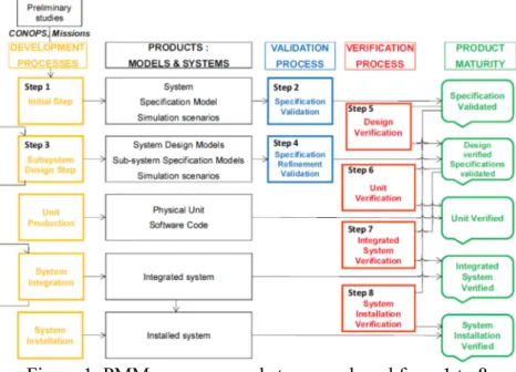
Figure 1. PMM processes and steps numbered from 1 to 8
Roughly described, PMM usually starts just after the validation of a Concept of Operations (CONOPS) [ISO/IEC/IEEE, 2011] and is made up of eight steps:
Figure 1.Step 1: Specification Modeling is carried out at the system level, is the development of a goal-oriented system specification model. The PMM concept of a specification model, collecting a set of PBRs, matches with the ARP4754A/ED79A definition of a specification (i.e. a collection of requirements).
Figure 1.Step 2: Specification Formal and Factual Validation, a formal validation of the system specification model is performed in order to complete it and to remove contradictions. On this basis, simulation scenarios are defined in order to factually validate the system specification model. So, PMM supports an early and rigorous validation process, before starting a solution definition process.
Figure 1.Step 3: Architectural Design and Requirement Refinement, we continue with an iterative process that consists in breaking down the system into subsystems. It is, by several aspects, a very classical process. It is acquainted with different design methods such as the Suh 's Axiomatic Design method [Suh, 2001]. Each subsystem is made up of a specification model and one or more design model alternatives. Thus, a collection of competing system’s architectures is considered, and then one is preferred. The subsystems and their connections constitute the system’s architecture. Figure 1.Step 4: Refinement Validation, at each hierarchical level, the subsystem specification models are validated individually and together against higher level subsystem specification model, from the system specification model to the lowest level. A subsystem is qualified as elementary when it is acquired or when it is not decomposed any further and its behavior is completely defined as a detailed design model. The design process ends when all the elementary subsystems have been identified, and modelled or acquired.
Figure 1.Step 5: Design Formal Verification, after this top-down design process, is a bottom-up process that consists in iteratively verifying the elementary design models and then the intermediate design models so as to finally end up with the complete system model. For each integration level, design models are integrated and verified against their own specification models. So, PMM supports a design verification process based on simulation before starting the physical implementation. Figure 1.Step 6 to 8: Implementation Factual Verification, the final steps that deal with the production/verification of the physical products (Hardware and Software), their integration/verification, and the final installation/verification of the system in its environment remains to be experienced practically. It is out of scope of this paper.
Note that each step of the PMM process includes recovery points, not represented here, to reengineer the system when a goal is not met at any step.
Furthermore, the process of modeling and simulating a function or system is not monolithically established once only. It is advised to establish it incrementally taking advantage of the additive and parallel nature of PMM constructs.
PBR concept: The core concept of PMM is the Property Based Requirement (PBRs) Theory defined in [Micouin, 2008]. PBRs are predicates that link system or function goals (outputs), observables (outputs) with inputs in order to specify the actualization conditions of system’s (resp. function’s) properties. The PBRs structure prevents introducing design biases at specification level. The same process applies for secondary (undesired) outputs such as system failures and inputs (expected or undesired). The PBR theory is based on the theory of properties established by the epistemologist Mario A. Bunge [Bunge, 1977]. Their basic form is as follows:
PBR #n : when C → val(O.P) ∈ D⊆Im(P)
This statement means: “when the condition C is true, the property P of the object O is actual and its
value shall belong to the domain D, where D is a subset of P image” where C is a relevant condition
for the system, the function or its environment: a functioning mode, a system state, an (undesirable) event, a time delay or a combination of such features, where the domain D is a finite set, such as {on,
off} or an infinite set, such as [0, 1]x [0, +∞[, (possibly linked to a frame and a physical unit) and where D is a subset of the set of actually possible values of the property P, quoted Im(P).
Based on Bunge’s property algebra, several PBRs can be combined thanks to the conjunction operator “∧” in order to build composite PBRs. In a dual way, the partial order relationships “≤” and “≥” enable analysts to compare two PBRs. Thus, the expression “PBR1 ∧ PBR2” is the conjunction of PBR1 and PBR2 and is itself a PBR. Moreover, the statement “PBR1 ≤ PBR2” means PBR1 is less constraining than PBR2. Thanks to these connectors, the specification model is endowed with an algebraic structure. Each PBR is an element of this structure whose maximum element is the specification model itself.
Context and use case description
A H/C provides its operators and passengers with many capabilities (or functions) depending on its operation phases that enable it to carry out its missions. If we focus our attention on the physical interface between the H/C and the ground, we can identify different capabilities the aircraft has to provide such as (1) "to absorb and to dissipate energy at landing" (2) "to maintain sufficient ground
clearance", (3) "to maneuver and to stop on the ground", (4) "to retract and to extend airborne landing gear" or (5) “to ensure landing gears and aircraft integrity", (6) and so on, as this list is not
complete.
In this paper, we have chosen to focus our attention on the "to retract and to extend airborne the landing gear" function. The purpose of this function is to provide the crew with the ability to reduce the aircraft drag (Landing Gears –LGs- in retracted position) and to provide it a means for landing (LGs downlocked in extended position). This function is a H/C function because it requires, on the one hand, the interaction of the crew for its control and its monitoring and, on the other hand, the cooperation of several H/C systems for its implementation, namely the Landing Gear System (LGS) as an effector system, a power system such as an Electric Generation and Distribution System (EGDS) or a Hydraulic System, and a control and supervision system such as an Avionics system. It is the proper operation and cooperation of these various systems that makes it possible to obtain the expected effects (functions) at H/C level.
Let us recall here informally some of the intended effects of this function. Some of these intended effects will be rigorously formalized in the next paragraph. We will justify the reasons of this necessary formalization in the next paragraph.
- REQ1: On ground as well as during take-off or landing phases, the landing gears (LGs) shall be fully extended and down-locked in order to prevent any retraction risk.
- REQ2: when a LG is fully extended and down-locked, then a green arrow shall signal ("on") in the cockpit and ("off ") otherwise, in less than 50 msec. The presence in the cockpit of these indicators is a specification assumption.
- REQ3: when the H/C is airborne and one LG, at least, is in retraction or in extension, then an indication "LG in progress" shall be displayed ("on") in the cockpit [, otherwise the indication
"LG in progress" shall be displayed ("off")]. The presence in the cockpit of the indication "LG
in progress" is a specification assumption
- REQ4: when the H/C is airborne, the LGS is in extension or down-locked [and the normal LG
control is not inhibited], if the crew sets in the normal LG control "up" position, then LGS shall
reach the "up-locked" position in less than 15 seconds, except in case of retraction failure . The presence in the cockpit of this normal LG control with two positions "Up" and "Down" is a specification assumption.
- REQ5: when the H/C is airborne and when the LGS is in retraction or up-locked [and the
normal LG control is not inhibited], if the crew sets in this normal LG control "Down" position,
- REQ6: when the H/C is airborne, if the crew sets in the "Down" position the emergency LG control, then [the normal LG control shall become inhibited in less than 50 milliseconds] and the LGS shall reach the "down-locked" position in less than 90 seconds excepted in case of Emergency Extension Failure. The presence in the cockpit of this emergency LG control with two positions "Off" and "Down" is a specification assumption.
- [REQ7: when the H/C is airborne and the LGS is down-locked and the normal LG control is
inhibited, if the crew sets in the emergency LG control’s "off" position and sets in the normal LG control’s "down" position, then the normal LG control shall become disinhibited].
- REQ8: A normal LG control failure shall not impair the emergency LG control. It is assumed here (ASSUMP1) that an emergency extension failure can have two causes: a fault of emergency control part or a fault of operative part while a normal extension failure can have two causes: a fault of normal control part or a fault of operative part of the LGS.
We also make the following additional assumptions and definitions, inherited from the H/C pre-development phase:
- The landing gear system LGS is tricycle system made up of a Nose Landing Gear (NLG) and two main landing gears (MLG: LLG for the left LG and RLG for the right one)
- Contact with the ground is elaborated from three redundant sensors (N, L and R) Weight on Wheel signaling a LG loaded or not.
- The H/C is on ground if and only if the three sensors signal a load (DEF1 in the sequel). - The H/C is airborne if and only if the three sensors signal no load.
At the time of the experiment, this function was under development in the frame of a new H/C developed by Airbus Helicopters and the experiment was considered as an aid for the actual development.
To specify the right function or the right system
Suh highlights in [Lee & Suh, 2006] that: “many designers deliberately leave their design goals
implicit and then start working on design solutions even before they have clearly defined their design goals. They measure their success by comparing their design with the implicit design goals that they had in mind, which may or may not what the customer wanted. They spend a great deal of time improving and iterating the design solution and "what they had in mind" converge”. This blurred and
hasty approach reported by Suh, is actually costly and inefficient and is opposed to the scientific approach, which prescribes defining a well-formed problem before attempting to solve it.
The PMM methodological guide for top-level specifications
PMM sets as paramount objective for the development team to specify the right system or function, i.e. system or function that meets the needs of its acquirer and other relevant stakeholders such as the crew, certification authorities or the safety service. If this goal is not achieved, the developed system may not meet the actual need.
Step 1 Specification Modeling:
To achieve this objective, PMM asks the development team to establish a specification model of the system or function to be developed. Conceptually, a specification model is a formal model including (1) system (respectively function) requirements, (2) system (resp. function) interface requirements and (3) system (resp. function) assumptions and (4) formal definitions. These features are expressed according to the Property Based Requirement (PBRs) Theory.
Thus, the development team expresses each definition, assumption and requirement that it thinks to be relevant for specifying the function in the form of a PBR. (1) Goals that are system outputs are modelled as inputs of the specification model. (2) Then the actualisation conditions of these goals are identified. These conditions are modelled either as observables or as expected inputs. (3) Eventually,
the result of the analysis is formalized as one or several PBRs packaged function by function, if necessary.
Here are some definition, assumption and requirements model examples:
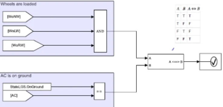
DEF1: The AC is on ground ↔ WOnNW = True and WOnLW = True and WOnRW = True where WOnW stands for Weight on Wheel, N, L and R stand for Nose, Left and Right. REQ6: when AC State = airborne and if Emergency LG control position ="Down" →
Normal_control_status = “inhibited” after 50 msec and LGS position = "down-locked" after 90 sec
REQ8: when LG.Normal_Control_fault ="true" → LG.Normal_control_fault = “false“
ASSUMP1: when LG.Emergency_Control_Fault ="True" or LG.Operative_Fault= “true”→ Emergency_Failure = “true“
Step 2 Specification Formal and Factual Validation:
Obviously, once determined, requirements are not miraculously correct, and once established, a specification is not miraculously complete either. They may include specification errors. This is why the ARP4754A/ED79A introduced a validation process of requirements and assumptions for engineering aircraft systems. The goal of the validation process is to remove specification errors. The PMM concepts of formal and factual validation deepen the concept of validation of requirements and assumptions defined by the ARP4754A/ED79A standard.
Certainly, representing requirements into formal models is more demanding than writing requirements in an informal and lax language, concealing all the pitfalls and ambiguities of natural languages, but it offers several advantages:
- it forces the specifier to formulate without ambiguity his/her expectations and prevents any form of procrastination, frequent when specifications are textual,
- formal modelling of a specification allows a formal validation of the top level system (resp. function) specification model. The compilation process of the models guarantees the syntactic coherence of the interfaces. More, PMM formal validation is a process to guarantee the formal completeness (no logical holes) and formal correctness (no logical contradictions) of specification model regarding its inputs and outputs possible values. When logical holes or logical contradictions are detected, the specification model has to be updated until the successful completion of the formal validation. In this case, the specification model is considered as formally validated.
- the simulation of a specification model formally validated linked with the corresponding specification mirror model allows a factual validation of the top level system or function specification model regarding a given set of validation scenarios. The goal of this process is to guarantee the factual completeness of specification model (stakeholders confirm there is no behavioural holes) and factual correctness (stakeholders confirm that the observed behaviours of the function or system are the right ones and none is missing). PMM factual validation is a process involving the relevant stakeholders such as program representatives, test pilots, flight engineers, safety representatives and authority or customers. It provides the stakeholders with a simulation of the expected behaviours of the function or the subsystem on the basis of the selected validation scenarios. When behavioural holes or incorrect behaviours are detected by the stakeholders, the specification model has to be updated until the successful completion of the factual validation. In this case the specification model is considered as factually validated. At end, when the specification model is formally and factually validated, it is presumed as error-free and it designates the right function or the right system. However, its physical feasibility remains an open issue, possibly covered by physical prototyping when risks are identified.
Implementation based on MATLAB and Simulink Products.
Specification modeling and specification validation:The PMM concept of a PBR can be easily implemented as a conditional assertion (Boolean function) with various simulation languages such as those mentioned above. Simulink provides a very convenient way to model them thanks to two blocks coming from Simulink libraries: Assertion and Implies blocks.
As examples, the following block diagrams model PBRs: definitions, requirements and assumptions:
Figure 2. DEF1: The HC is onGround, if and only if Weight on Wheels are “on”.
Figure 3: REQ6 Simulink Implementation
Figure 4. Safety analysis ASSUMP1: Emergency extension failure and its possible causes
A PMM specification model can be easily implemented as Simulink subsystem embedding a set of conditional assertions operating concurrently on the specification model inputs.
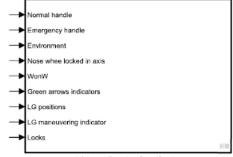
As an example, the following block diagram models a specification model of the extension/retraction function.
Figure 6. Specification Model for the extension/retraction function at Helicopter level. Note that a specification model has only inputs and no outputs. The specification model inputs are connected to system model and design model inputs, outputs and probes (observables).
Figure 7. PMM System Model including a Specification Model and a Design Model interconnected During a simulation run, the specification model monitors the design model and checks its compliance status with respect to requirements at each simulation step. In case of requirement violation, the violation is logged and the simulation may be stopped.
Specification Formal Validation: Formal validation of a specification model is supported by Simulink Design Verifier, a tool belonging to the MATLAB and Simulink product list. Basically, it provides several means to verify Simulink models including (1) formal methods to identify hidden design errors and (2) test inputs generation for model coverage and custom objectives.
At this stage of the development, we use Simulink Design Verifier to detect logical holes or logical conflicts in the specification model in order to complete and to correct it, when necessary.
Specification logical hole:
A logical hole may occur when the conditions for which O.P shall be in Im(P)-D remain unspecified, while O.P shall be in the domain D when C is true or when a condition value remains unspecified. As an example of logical hole, in the use case description above section (REQ3), the removal of the phrase dealing with the conditions under which the "LG in progress" indicator shall be "off" (marked with square brackets [] and italic text) introduces an (intentional) logical hole in the specification. Specification logical contradiction:
A logical contradiction occurs in the following context: O.P shall be in the domain D and simultaneously in the domain D’ when C with D∩D’=Ø (empty set).
As an example of logical contradiction, in the use case description above (REQ7), the removal of the phrases dealing with the inhibition/disinhibition of the normal control (marked with square brackets [] and italic text) makes room for a logical contradiction in the specification in the following conditions: the H/C is airborne, if the normal LG control is set in "Up" position (retraction order) and the emergency LG control is set in "Down" position (emergency extension order).
Simulink Design Verifier provides computational means to detect such logical holes or such logical contradictions when the specification model is instrumented with the relevant proof (or test) objectives and submitted to the analysis of the Simulink Design Verifier proof engine or test generator. In our case, it is capable of falsifying proof objectives or test objectives and of exhibiting counter examples putting the specification model at fault . Simulink Design Verifier confirms that the hole has been removed as soon as the conditions for which the indicator shall be "off" or as soon as the inhibition/disinhibition mechanism have been modeled in the specification.
Specification Factual Validation:While PMM formal validation of a specification model is a matter of models coherence, factual validation is a matter of model consistency with respect to an extra-modeling reality such a legal reality or a contractual reality (the distinction between formal coherence and factual consistency relies on the difference between formal truth and factual truth [Leibniz, 1714]): the expectations of relevant stakeholders such as those of acquirers, operators, regulation authorities and so on. The factual validation of specification model should rely on a model previously formally validated.
Factual validation requires the definition of three additional artifacts: (1) a validation bench and (2) a particular model, called specification mirror model (3) Validation scenarios.
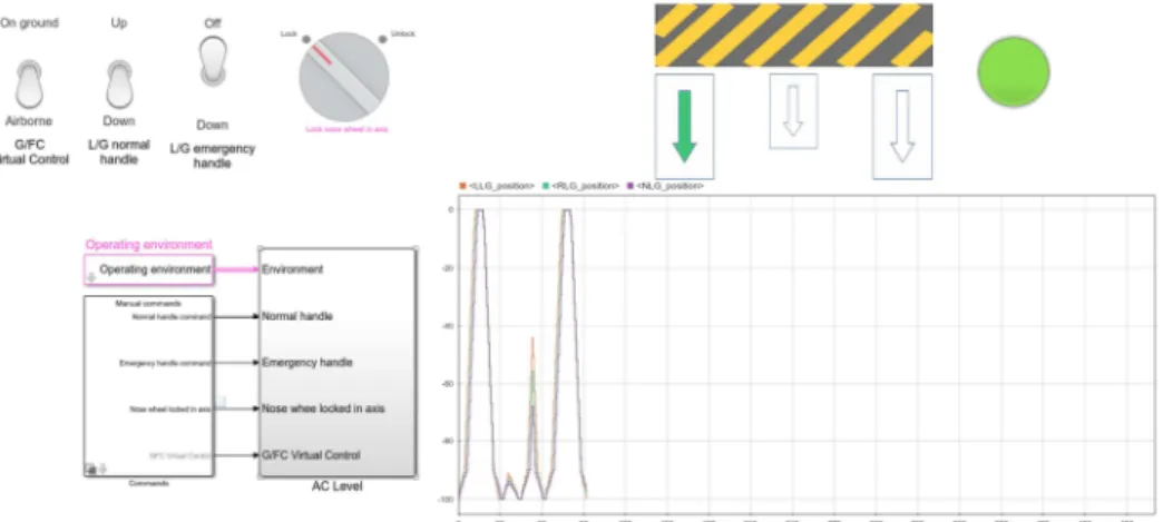
Figure 8. Factual validation bench (Snapshot).
The figure 8 shows a bench developed in order to factually validate the LGS extension/retraction function. It includes:
- at the top left side, relevant actual LG controls and one virtual button to control the ground/flight condition,
- at the bottom left side, environmental conditions (OAT, Airspeed and load factors) affecting the extension/retraction of the LGS and the manual or recorded to replay control scenarios,
- at the middle the AC level function model,
- at the top right side, the relevant actual LG indicators, LGS in progress indicator and Green Arrows and Nose Wheel Locked in Axis indication.
- at the bottom right side, a graphical visualization of LGs position evolutions between 0 (fully retracted position) and -100 (fully extended position).
Basically, a validation bench represents the system to be validated in its operation environment. As shown on the figure 8, the LGS is, at the snapshot time, normally extending, and just the RLG is already down locked while the other LG are not yet completely extended and locked. This is the reason why the Right Green Arrow shall be “on”, the others shall be “off” (compliance with REQ2), while the "LG in progress" indication shall be “on” (compliance with REQ3).
The goal of the validation bench is to show the stakeholders how the system is expected to behave in different situations of its operational life. Stakeholders are expected to comment on these behaviors: they may agree with them, reject them, ask for additions or changes. The specification model has to be reworked and the factual validation ends when the behavior shown is agreed and committed by the relevant stakeholders.
The validation process is based on validation scenarios built relying on the system CONOPS and additional scenarios including failure scenarios, emergency procedures, handling errors, and so on. Note that the following points are not documented here: (a) Validation scenarios are performed manually and can be recorded for later replay. Systematic scenarios based on Simulink Design Verifier capabilities are also possible to reach a defined validation level of rigor according to the ARP4754A/ED79A recommendation (b) the specification mirror model is a design doing exactly what the specification model is expecting.
On the LGS project, the use of the validation bench allowed to confirm with the test crew the simulated behaviors, to clarify the expected behaviors during an emergency extension sequence of landing gears, to request the specification of additional requirements for new warnings in some circumstances, etc.
In the following table is shown how the PMM formal and factual validations cover the validation aspects of the ARP 4754A recommendation:
Table 1: ARP 4754A validation goals and PMM coverage ARP 4754A validation
aspects
PMM
Formal validation Factual validation Correctness No logical contradiction
proof or test
Correctness commitment by stakeholders based on an objective basis (specification
model)
Completeness No logical hole proof or test Completeness commitment by stakeholders based on an objective basis
To design and to implement the function or the system right
Figure 9. Zigzagging between specification and design domains.
As shown in figure 9, and in accordance with Suh’s Axiomatic Design [Suh, 2001], system models “must be decomposed until we get a complete detailed design or until the design is complete.
However, contrary to conventional wisdom on decomposition, they cannot be decomposed by remaining in design domain only. One must zigzag between the specification and design domains to be able to refine requirements and design parameters”.
PMM methodological guide for architectural design and requirements refinement Step 3 Architectural Design and Requirement Refinement: Based on a formally and factually validated specification model, the design phase can be initiated. One candidate architecture description of the system or the function is introduced in the form of a design model comprising subsystem models and links between these subsystem models (internal interfaces) and the links with the system model external interfaces. Subsystems modeled can be discrete (causal) with signals links (unidirectional) or continuous (acausal) with links power flows (bidirectional) or else hybrid (including discrete and continuous parts) with signals and power flow links. As an example, LGS extension/retraction function is distributed on several aircraft systems including avionics, electrical, hydraulic and mechanical landing gear systems. Alternate design models can be considered to seek for the best (Time, Cost, Quality, Performance) TCQP design trade-off.
According to the Suh’s zigzagging masterful view, system level PBRs have to be refined into subsystem PBRs allocated to the various subsystem models composing the considered architecture in order to assign to each subsystem its role and responsibilities to achieve the system goals. These subsystems PBRs derive from the system PBRs and from the architectural design choices.
Figure 10. Subsystem specification models validation wrt System specification model
Design activity and PBRs refinement involve knowledge of the various engineering disciplines concerned as well as those of the safety specialists. It also calls for collaborative working between the different engineering discipline designers to share a common goal, to agree roles and responsibilities for each system and to make the necessary tradeoffs. The material basis on which this collaborative work is carried out is the design model. It constitutes a common objective reference on which mutual commitments (subsystem PBRs and interfaces) are based, as well as a contractual design practice. Step 4 Refinement Validation: According to PMM, before separating and further developing the various subsystems concurrently, the team has to validate the refinement of the system PBRs into subsystems PBRs to ensure that this refinement is correct and complete and does not lead to incoherencies or to gaps. To be valid, for a given system design model A, the conjunction of the refined PBR1, …, PBRn assigned to subsystems must be more constraining than the system PBRs.
When A → PBR ≤ PBR1 ⋀ ... ⋀ PBRn
In this case, according to the PMM Prime Contractor Theorem, if each physical subsystem meets its commitments (specification) then the system integrated in accordance with its design model will respond to its own specification.
PMM system design phase ends when no further design decomposition is needed and when detailed design models are established by the designers (internal or external in case if the lower level is delegated to a supplier) on the basis of the knowledge of their respective engineering disciplines. Step 5 Design Formal Verification: As any implementation product made by humans, design models may include design errors. So, they have to be verified in order to remove design errors, to ensure that fault tolerance and reconfiguration mechanisms are really efficient and then to produce a physical system free of design error.
While specification, design modeling and specification validation are interleaved and top-down (“zig-zagging” in the words of N.P. Suh) processes, design model verification is performed in a bottom-up process:
1- First, the lowest level design models are verified regarding their own specification model. 2- Second, the lowest level design models can be (1) integrated and (2) the resulting integrated
design model can be verified regarding the corresponding specification model
3- Lastly, the integrated design models can be (1) integrated to produce the top level design model and installed in its simulated environment (2) the top level design model can then be verified regarding the top level specification model on the basis of operational scenarios.
This design verification process has to be performed with a level of rigor corresponding to the required Design Assurance Level (DAL) of the subsystem and verification scenarios have to be built in order to test the design model compliance with the specification model. At any level, the design models have to be formally verified: i.e. discrepancies between the design model outcomes and the expectations of the previously validated specification model have to be searched for and can be detected during simulation runs. In that case, design model should have to be corrected in order to comply with its specification model. This process ends when all the design models from the bottom to the top level comply with their respective specification models. Then, they are considered as formally verified.
Step 6 to 8 Implementation Factual Verification: As stated above, step 6, 7 and 8 (verification of physical implementations) is not documented in this paper.
Implementation based on MATLAB and Simulink Products
Simulink and Stateflow, possibly associated with Simscape, provides capabilities for building design models including discrete subsystems, continuous subsystems and hybrid subsystems linked as appropriate by signals and/or power flows in order to design systems including avionics, mechanical and electrical subsystems. These links can represent functional or physical bonds depending on the system development stage.
Figure 11. Landing Gear Function Design Model.
Figure 11 represents an architectural design model of the LGS extension/retraction function that introduces the contributing subsystems: the LGS itself connected to others contributors: a hydraulic
system, an electrical system, avionics and LG panels for controls indications and alerts. Connections are unidirectional for signals and bi-directional for power flows.
Additionally, Simulink provides the “reference system” feature allowing to model concurrently and separately the design of each subsystem composing the elements of the system design model with its specified requirements.
Again, Simulink Design Verifier provides us with a validation means for the refinement of system (resp. function) PBRs into PBRs subsystems. For this purpose, the objective of the proof to establish is that each system PBR must be satisfied as soon as all the subsystem PBRs that refines it are also true. This is the exact translation of the PMM Prime Contractor Theorem. Otherwise, a PBR refinement error has been made and must be corrected.
With appropriate tools, design models including continuous subsystems and hybrid subsystems linked as appropriate by signals and/or power flows are built to model and simulate the behavior of mechanical, hydraulic, thermal and electrical subsystems according to their connections. These connections can represent functional or physical bonds depending on the system development stage.
Figure 12. Hydraulic PhysicalDesign Model.
Figure 12 represents the hydraulic design model introduced for controlling the LGS extension/retraction mechanism. It introduces the contributing components: tanks, pumps, pipes, valves, monitoring indicators and hydraulic ports. Note here how the PMM systems engineering is close to the concerned engineering discipline and to its own language.
Figure 13. Multibody PhysicalDesign Model of LG.
Figure 13 represents a mechanical design model of the LGS extension/retraction mechanism. It introduces the contributing components: cylinders converting hydraulic power into displacements of the landing gear parts according their mechanical links in the relevant geometrical frames. Parts or assembly models are imported from a 3D Aircraft Digital Mock-Up ensuring the consistency of data with our PMM functional and behavioral mock-up.
Simulink and Stateflow provide capabilities for building design models representing discrete subsystems that can be transformed into as software code or simple or complex electronic hardware in order to design avionics or others Airborne Electronics Hardware (AEH).
Then, in order to (1) develop several alternate design models of the same system, and (2) to freeze significant stages of system development, including factual validation, functional design and physical design stages, Simulink provides the “variant system” feature allowing to model several alternate design models with the same definite external interfaces and simulate any of them by simple configuration before a simulation run.
The last point, which could not be established in the context of the reported experiment, was to generate, for discrete systems, systematic verification sequences according to the level of rigor related to the Design Assurance Level (DAL) assigned to the function or the system considered. For this purpose, the process is
(a) To defined the verification (test) objectives ensuring the required level of DAL, (b) To instrument the specification models with the relevant verification objectives,
(c) To generate, using Simulink Design Verifier, the right sequences of inputs, driven by the instrumented specification models; and recorded in a “signal builder”.
(d) To launch the builder signal that will stimulate the models the design models while the specification models monitor design models outputs.
Note that the design verification sequences are recorded in the signal builder and may be used for similar usages (e.g. to verify physical products themselves).
Lessons learnt and industrial perspectives
Confirming the preliminary results of the previous POCs, the experiment showed practically the feasibility and relevance of the PMM process on an actual full scale case. It has helped to remove ambiguities in first level specifications. It enabled the test pilots to validate the expected behavior specified by the top level specification model. It initiated a collaborative design working and it also helped in the establishment of subsystem specifications for suppliers. Although the demonstration is not complete for implementation verification aspects, it supports the claim that PMM reduces the time and risk of system development and consequently the system development non-recurring costs. At the same time it increases the maturity of the system definition. In this experiment, the MATLAB and Simulink products proved to be well adapted to the PMM methodological expectations while we benefit from very mature means. This confirms our vision on PMM enabling capacity to drastically improve efficiency in H/C complicated system developments.
Currently, PMM provides means to model failures and faults and to specify the expected behavior in case of faults, to design systems avoiding or tolerating faults by redundancies and reconfiguration mechanisms and to demonstrate the compliance of these designs with the safety requirements. However, it remains for PMM to provide a systematic way to echo safety analyses and connect safety activities with development activities to support a Model Based Safety Assessment (MBSA) in accordance with the ARP 4761A [SAE, forthcoming] that should be released soon.
Complexity Reduction: PMM method, shared with partners and suppliers, should strongly ease the challenge of complicated aircraft development in such a globalized design organization context. The unambiguous and formal aspect of PMM, relying on an objective basis provided by simulation should provide means to improve cooperation among organizations, to prevent and overcome misunderstandings, introduced by cultural differences and that abound in current development organizations. In addition, technical basis of contractual work share among industrial alliances will be more efficient and leaner by providing a formal definition of roles and responsibilities and technical commitments.
Digital Continuity: While the digital continuity provided by digital engineering documents may be questionable, the PMM methodology, with its simulable digital products (specification and design models, interface dictionaries and V&V scenarios) provides a powerful conceptual framework to support digital continuity while transferring its openness to the interoperability of simulation environments.
Reuse: PMM provides means to transform a large amount of specification and design patterns as assets for reusing them in subsequent or derivative developments, paving the way of a very industrial and effective development process of technological systems. So, progressively after several program deployments the PMM will even more facilitate efficiency in product lines development through straightforward and efficient reuse.
Acknowledgements
Authors warmly thank A. Jenni (head of Vehicle Systems and Installations), C. Haefflinger (head of Vehicle Basic Systems) and V. Pacheco (head of Landing Gear Systems) for their kindness and their support during this experiment, M. Achache (Executive Manager Technical Audit Avionics)for his relevant comments on the paper, R. Pinquié, A. Barouni and V. Paredes for their contributions during the experiment and finally L Espié & J Wirtz for having sponsored PMM project through Airbus Helicopters R&D Method&Tool fundings.
Property Model Methodology (PMM) is a registered trademark of Patrice Micouin
MATLAB and Simulink are registered trademarks of The MathWorks, Inc. See mathworks.com/trademarks for a list of additional trademarks. Other product or brand names may be trademarks or registered trademarks of their respective holders
References
Suh N.P, 2005, Complexity, Theory and Applications, Oxford University Press.
Micouin, P. 2014: Model Based Systems Engineering: Fundamentals and Methods, Wiley & ISTE . SAE, 2010, ARP4754A, Guidelines for Development of Civil Aircraft and Systems, Warrendale
(PA).
Bunge M., 2007, Philosophy of science, volume 1: from problem to theory, Chapter 1, the scientific approach, Transaction Publishers, New Brunswick, New Jersey, 4th print.
Micouin P, Fabre L, Pandolfi P, 2016: Property Model Methodology: A First Assessment in the Avionics Domain, ERTSS 2016.
Pinquié R, Micouin P, Véron Ph, Segonds F, 2017: Property Model Methodology: a case study with Modelica, TMCE 2017.
ISO/IEC/IEEE, 29148, 2011, “ISO/IEC/IEEE International Standard - Systems and software engineering -- Life cycle processes -Requirements engineering
Suh N.P, 2001, Axiomatic Design Advances and Applications, Oxford University Press.
Micouin, P., 2008, “Toward a property-based requirement theory: system requirements structured as a semilattice”, in: Systems Engineering, Vol. 11-3, pp. 235-245.
Lee D.G, Suh N.P, 2006, Axiomatic Design and Fabrication of Composites Structures, Oxford University Press.
Leibniz, G.W., 1714, “Monadology”.
http://home.datacomm.ch/kerguelen/monadology/monadology.html (accessed on 13 March 2018) “There are also two kinds of truths, those of reasoning and those of fact. Truths of
reasoning are necessary and their opposite is impossible: truths of fact are contingent and their opposite is possible.”
SAE, forthcoming, ARP4761A, Guidelines and Methods for Conducting the Safety Assessment Process on Civil Airborne Systems and Equipment, SAE, Warrendale (PA).
Bunge. M, 1977, Treatise on Basic Philosophy, vol 3, Ontology I: The furniture of the World, D. Reidel Publishing Compagny.
Patrice Micouin
I’m the inventor of the Property Model Methodology (PMM). As a late outcome of my PhD in the Automotive Systems Engineering domain (2006), I published in the Systems Engineering Journal (2008) a disruptive theory of Property-Based Requirements (PBRs). The lack of an engineering methodology tightly related to engineering disciplines and providing a vehicle for my PBR theory, as well as my practice of simulation languages gradually led me to propose a systems engineering method: PMM. Targeting initially causal systems, I extended it to multiphysics systems. Currently, I work for the Airbus Helicopters Design Office.
Pascal Paper
In Airbus-Helicopters R&D Method, I lead engineering transformation project relying on Property Model Method to increase system designer efficiency. From 2005 to 2012, I leaded transnational Multi-System Physical Integration department in AIRBUS aircrafts. Between 1999 and 2005, I leaded Airbus Concurrent Engineering deployment for series programs and A400M. From 1992 to 1999, I leaded lofting & master geometry in Aerospatiale Aircraft. From 1989, I was responsible for 3D method within Aerospatiale space leading a project aiming to set up configured DMU for ARIANE 5. I started my career in Dassault-Aviation on a PHD on Radar Cross Section numerical 3D computation.
Louis Fabre
I’m the Senior Expert for software and system of software at Airbus Helicopters R&D directorate, coordinating an expertise group in the “cockpit design, computers and software” department. I’m acting in the airborne software domain for around 30 years, starting at Aerospatiale commercial aircraft and then at Airbus Helicopters, covering a wide range of activities from development, verification up to certification aspect. I participated to the early trials of PMM identifying quickly the potential of the method to support an early formal definition and validation of systems requirements and design, allowing reducing the amounts of open problems at software level.
Thomas Razafimahefa
I am working in landing gear design office from Airbus Helicopters, my department is responsible to develop wheels landing gears for medium and heavy helicopters. I work in this department since 9 years and I was involved on several domains of this system such as: supply chain technical support focal point, installation & integration responsible (installation & definition drawings, procedures…), system engineering responsible (specification, certification document redaction, supplier management) . Now I am in charge to modelize landing gears systems through simulation tools to validate systems expectations. I am working in the group which implements the Property Model Methodology.
Roland Becquet
With 17 years of experience in landing gear design, I have been involved in several landing gear developments either as structural analysis engineer or as design engineer, both in SAFRAN Landing Gears and in Airbus. I have been an Airbus Helicopters’ Landing Gear expert and ATA32 (landing gear) compliance verification engineer (CVE) since 2016. In the expert role, I actively participated, either as writer or as validator, to Airbus Helicopters ATA 32 specification based on the “Property Model Methodology”. In addition to expert activities, I am in charge in the design office of the continuing airworthiness activities of landing gears.
François Guérin
François Guérin is a principal technical consultant with over 10 years’ experience assisting companies in the implementation and optimization of Model-Based Design. He specializes in providing guidance for the development of high-integrity systems in aerospace and rail. Prior to joining MathWorks, François was a member of the Control Distributed and Automation group of the University of Cambridge, and a software engineer at Alten France. He received a B.Eng. in European engineering and an M.S in control engineering from Coventry University.