HAL Id: tel-02999129
https://tel.archives-ouvertes.fr/tel-02999129
Submitted on 10 Nov 2020HAL is a multi-disciplinary open access archive for the deposit and dissemination of sci-entific research documents, whether they are pub-lished or not. The documents may come from teaching and research institutions in France or abroad, or from public or private research centers.
L’archive ouverte pluridisciplinaire HAL, est destinée au dépôt et à la diffusion de documents scientifiques de niveau recherche, publiés ou non, émanant des établissements d’enseignement et de recherche français ou étrangers, des laboratoires publics ou privés.
Partial oxidation of methane in a dielectric barrier
discharge plasma milli-reactor
Erick Osvaldo Martinez Ruiz
To cite this version:
Erick Osvaldo Martinez Ruiz. Partial oxidation of methane in a dielectric barrier discharge plasma milli-reactor. Chemical engineering. Université Pierre et Marie Curie - Paris VI, 2017. English. �NNT : 2017PA066736�. �tel-02999129�
Université Pierre et Marie Curie
Ecole Doctorale 391 - Sciences Mécaniques, Acoustique, Electronique et
Robotique
Equipe 2PM / IRCP UMR8247 (CNRS-Chimie ParisTech)
Oxydation partielle du méthane dans un milli-réacteur
plasma de type décharge à barrière diélectrique.
Partial oxidation of methane in a dielectric barrier discharge
plasma milli-reactor.
Par Erick Osvaldo MARTINEZ RUIZ
Thèse de doctorat en Génie des Procédés
Dirigée par Stéphanie OGNIER
Présentée et soutenue publiquement le 23 mai 2017
Devant un jury composé de :
M. COMMENGE Jean-Marc Professeur Université de Lorraine Rapporteur M. FULCHERI Laurent Maître de conférences HDR MINES ParisTech Rapporteur Mme. GALVEZ Maria Elena Maître de conférences HDR UPMC Examinateur Mme. OGNIER Stéphanie Maître de conférences HDR ENSCP Examinateur
3
A mi familia.
Especialmente a mis abuelos,
Nazaria y Jesús.
5 Acknowledgments
Je tiens à remercier en premier lieu ma directrice de thèse : Madame Stéphanie OGNIER, Maitre de conférences HDR ENSCP pour toutes les heures qu'elle a consacrées à diriger cette recherche. Monsieur Michaël TATOULIAN, Professeur ENSCP et Directeur de l’équipe Procédés, Plasmas et Microsystèmes pour m’avoir accueilli au sein du laboratoire et pour ses précieux conseils tout au long de cette thèse.
J’adresse mes sincères remerciements à Monsieur Jean-Marc COMMENGE, Professeur Université de Lorraine et à Monsieur Laurent FULCHERI, Professeur à MINES ParisTech pour l’honneur qu’ils m’ont fait en acceptant d’être rapporteurs et membres du jury de ce travail.
Mes remerciements s’adressent également à Madame Maria Elena GALVEZ, Maître de conférences à l’Université de Pierre et Marie Curie, pour avoir accepté de participer au jury de ce mémoire de thèse.
Je remercie Monsieur Safwan AL AYOUBI et Monsieur Simeon CAVADIAS, ¨pour leur aide et leurs conseils. Merci pour le temps consacré à cette thèse.
Je ne saurais oublier que ce travail a été possible grâce au soutien financier du Consejo Nacional de Ciencia y Tecnología (CONACyT).
Personal Acknowledgments
Gracias a Imelda Ortiz por ser mi gran pilar en esta gran aventura. Tantas experiencias compartidas, así como, batallas superadas, definitivamente nunca lo olvidaré. Esto no lo hubiera logrado sin ti.
Un gran gracias a mis otros tres pilares Guillaume Schelcher, Olivier Lesage y XI Rao. Ustedes forman parte de mi familia, gracias por ensenarme el profundo valor de su cultura e historia, por siempre serán mis hermanos.
Un especial gracias a Cedric Guyon y Frédéric Rousseau, el binomio incondicional que tanto admiro como profesional como humanamente.
6 Gracias a todo el equipo de Génie des procédés del CNAM dirigido por Jean-Louis Havet, los cuales siempre me acogieron y brindaron su apoyo, tanto moral como académico.
Gracias a Bradley y Alex por su aportación en contrastes ideológicos, y su siempre soporte moral que me brindaron.
Gracias a Aurelien y Julien, los cuales fueron de gran importancia, para lograr a la perfección el “Último estirón” en esta aventura.
Gracias a Mengxue por sus aportes teóricos, experimentales y a veces “políticos” para el buen desarrollo de mi trabajo.
Gracias a Axelle, Charlotte, Dhia, Diane, Jonathan, Maxime, Rafik, Wael, Sylvan, Paul, Matis, Manon (gracias por los postres), Stuart, Ines, y Magdalena. Por simplemente ser quienes son y transmitirme su valía.
Un Especial gracias a Phat que en este último trayecto formo parte importante en mi guía a la meta final.
Gracias a todos mis amigos tan cercanos que en todo momento me tendieron todo su apoyo incondicional: Kader (Adrien), Xavier, Olivier, Charles Cavaniol.
7 Abstract
Methane gas is known to be the most destructive greenhouse gas. The current world reserves of natural gas, which contains mainly methane, are underutilized due to high transportation costs. Thus, considerable interest is presently shown in conversion of methane to transportable liquid fuels and chemicals of importance to the petrochemical industry. One of the main solution for this problem is the partial oxidation of methane, actually this reaction requires a very high pressures and temperatures.
The partial oxidation of methane (POM) in a milli-plasma environment is one possible route for converting methane to more valuable higher hydrocarbons at room temperature and atmospheric pressure.
In that context, a Dielectric Barrier Discharge (DBD) transparent plasma-millireactor was designed for methane partial oxidation. A mixture of O2/CH4/Ar was processed into the reactor. AC high voltage (10.8 kV, 3 kHz) was
applied to generate the plasma discharge. Under our experimental conditions, a highly reactive environment at room temperature and atmospheric pressure was generated, leading to methane conversion as high as 30 percent. The main products of the reaction were identified as methanol, ethane, ethane, propane, hydrogen, CO and CO2.
The influence of the specific input energy (J/molmethanein), the gas composition and flow rate on the methanol
selectivity and methane conversion were studied.
Comsol Multiphysics 5.1 was used as a simulation tool to perform a first study to understand the mechanism of the reaction involved in POM for the production of methanol. Two main models were discussed, the sinusoidal and multi-time scale models. This work defines the bases for the understanding of the POM for the production of methanol. This study generates new alternatives in the use of miniaturization technologies in order to efficiently convert methane to methanol.
Résumé
Le gaz méthane est connu comme le gaz à effet de serre le plus ravageur. Les réserves mondiales actuelles de gaz naturel, qui contient principalement du méthane, sont sous-utilisées en raison des coûts de transport élevés. Subséquemment, un intérêt important est démontré dans la conversion du méthane en carburants liquides transportables et en produits chimiques d'importance pour l'industrie pétrochimique. L'une des principales solutions à ce problème est l'oxydation partielle du méthane (POM acronyme en anglais), cette réaction nécessite des pressions et des températures très élevées.
L'oxydation partielle du méthane dans un milieu milli-plasma est une voie possible pour convertir le méthane en hydrocarbures supérieurs avec plus de valeur à conditions de température ambiante et pression atmosphérique. Dans ce contexte, un milli-réacteur plasma de type décharge à barrière diélectrique a été conçu pour l'oxydation partielle du méthane. Un mélange d'O2 / CH4 / Ar a été utilisé, à une haute tension CA (10,8 kV, 3 kHz) pour générer
la décharge du plasma. Dans les conditions expérimentales, un environnement hautement réactif à température ambiante et pression atmosphérique a été généré, ce qui a conduit à une conversion du méthane jusqu'à 30 %. Les principaux produits de la réaction ont été identifiés comme le méthanol, l'éthane, l'éthane, le propane, l'hydrogène, le CO et le CO2. L'influence de l'énergie d'entrée spécifique (J / molmethanein), la composition du gaz, le
débit sur la sélectivité au méthanol et la conversion du méthane ont été étudiés. Comsol Multiphysics 5.1 a été utilisé comme outil de simulation pour effectuer une première étude pour comprendre le mécanisme de la réaction impliquée dans la POM pour la production de méthanol. Deux modèles principaux ont été discutés, les modèles à l'échelle sinusoïdale et multi-temps. Ce travail définit les bases de la compréhension du POM pour la production de méthanol. Cette étude génère de nouvelles alternatives dans l'utilisation des technologies de miniaturisation afin de transformer efficacement le méthane en méthanol.
9 General introduction
The objective of this research was to build and study an atmospheric pressure non-thermal dielectric barrier discharge (DBD) plasma millireactor aimed to produce methanol by partial oxidation of methane.
Today, it is evidently noticed that public sensitivity regarding environmental issues has increased substantially in comparison with a recent past, due to the drastic exploitation and depletion of fossil fuels including oil and coal which have a great influence on environmental problems such as the global warming.
In addition as a consequence of burning of these carbon-based fuels the concentration of greenhouse gases increases mainly those concerning CO2 and CH4, the second
one has until 30 more impact effect in the global warming phenomena in comparison to CO2. In the other hand, a renewed interest in gas-to-liquid processes has been
initiated by the increasing legislation for cleaner energy sources, which includes the production of liquid fuels from biomass derived sources. Another reason for interest in these reactions comes from the natural gas industry, where gas-to-liquid conversions, if carried out at remote offshore locations, could enable some governments to profit from stranded natural gas reserves at oil wells where the natural gas by-product is otherwise flared
However, methane is a very stable molecule due to the high strength of the four C-H bonds. Adverse reaction conditions are necessary in order to overcome the high activation energies required to break these bonds. Established industrial methods for methane reforming involve reacting CH4 with steam or another oxidant under high
temperatures, pressures and in the presence of catalysts that are prone to sintering and deactivation under these harsh operating conditions.
Nowadays, non-thermal discharges at atmospheric pressure are of great interest in many fields owing to the highly reactive environment provided at relatively low temperatures. Moreover, cold plasma processes are promising systems in order to be environmentally friendly and an energy saving processing route. Miniaturization of plasma reactors has the promise of producing the plasma at much lower voltages compared to a conventional scale reactor, thus achieving low power production. In addition, the milliscale dimensions increase the efficiency of both heat and mass transfer phenomena, and so provide a nearly isothermal and rapidly mixed
10 homogeneous environment allowing a better control of the chemical reactions. Thus, generation of plasma in micro and millichannels may lead to a better control of chemical transformations. Plasma reactors used as a milliscale source of ions, excited species and radicals open several opportunities for the chemical process intensification and could be an enabling technology across fundamental and applied sciences.
In that context, a Dielectric Barrier Discharge (DBD) plasma-millireactor was designed for the partial oxidation of methane. The millireactor was designed to operate at atmospheric pressure and possible temperature increases due to the nature of the reaction. It is possible to realize optical characterizations using a camera ICCD (intensified charge-coupled device) since the reactor possesses a transparent electrode elaborated with an alloy of Indium Tin Oxide (ITO)
In this thesis are studied and discussed the influence of the main operating variables of the DBD plasma millireactor for the POM for the production of methanol. Those variables are the composition of the reactive mixture, flow rate and injected power into the system. These variables were studied using characterization techniques such as gas chromatography (GC) and the use of the ICCD that allowed to evaluate the uniformity in the distribution of plasma discharges in the reactor.
There is also reported the use of Comsol Multiphysics 5.1 as a simulation tool to perform a first study to understand the mechanism of the reaction involved in POM for the production of methanol as well as the behavior of the intermediate species generated in the plasma discharge. In this thesis are proposed two main models to achieve this goal, the sinusoidal model and multi-time scale model. The advantages and disadvantages of each are discussed in this thesis.
11 Contents Acknowledgments Abstract General Introduction : Literature review ... 15 1.1. Introduction ... 17 1.2. Natural gas ... 18
1.3. Global climate change ... 19
1.3.1. Biogas ... 22
1.4. Fischer-Tropsch processes ... 24
1.5. Industrial methanol synthesis ... 27
1.6. Introduction to plasma ... 28
1.6.1. Applications of plasma ... 29
1.6.2. Types of plasma ... 30
1.6.3. Generation of non-thermal plasma by electric fields ... 31
1.6.4. Townsend mechanism of electric breakdown ... 33
1.6.5. Continuous and pulsed direct current discharges ... 35
1.6.5.1. Corona discharges ... 3637
1.6.5.2. Gliding arc discharges ... 39
1.6.5.3. Dielectric barrier discharges (DBD)... 40
1.6.5.3.1. Microdischarges ... 41
1.6.5.3.2. Memory effect in DBD plasma ... 41
1.7. Plasma chemistry for methanol production ... 42
1.7.1. Plasma reactor designs for partial oxidation of methane (POM) ... 42
1.7.2. CH4/O2 ratio ... 46
1.7.3. Noble gas effect ... 47
1.8. Conclusion ... 48
: Analytical techniques ... 49
2.1. Plasma power measurements ... 51
2.2. Intensified charge coupled device (ICCD) ... 52
2.3. Gas chromatography ... 53
2.3.1. Micro-gas chromatography ... 55
2.3.2. Thermal conductivity detection ... 57
2.3.3. Flame ionization detection ... 58
2.4. Conclusion ... 59
: Fabrication and performance of a DBD plasma milli-reactor ... 61
3.1. Introduction to milli-reactor development ... 63
3.2. Reactor fabrication ... 65
3.2.1. Plasma milli-reactor cellule fabrication ... 65
3.2.2. Borosilicate glass engraving ... 66
3.2.3. Electrode patterning ... 67
3.2.4. General description of the sputtering process ... 68
3.2.5. Electrode deposition for POM ... 69
3.2.6. Electrode deposition for discharge characterization ... 70
12
3.3. Electrical characterization of the reactor ... 73
3.3.1. Influence of the argon percentage on the electrical characteristics of the discharge .. 77
3.3.2. Influence of the O2/CH4 ... 78
3.4. Characterization of discharge uniformity by ICCD measurements ... 78
3.4.1. ICCD measurements in pure gases ... 78
3.4.2. ICCD measurements CH4/O2/Ar mixture ... 79
3.5. Conclusion ... 82
: Performance of the plasma milli-reactor for the partial oxidation of methane (POM) ... 83
4.1. General performance for partial oxidation of methane (POM) ... 85
4.2. Methane to methanol in a plasma milli-reactor ... 89
4.2.1. Influence of flow rate on methanol selectivity (ICCD) ... 89
4.2.2. Influence of argon concentration on methanol selectivity ... 93
4.2.3. Influence of the O2/CH4 ratio on methanol selectivity ... 96
4.3. Conclusion ... 99
: Simulation of a DBD plasma milli-reactor for POM ... 101
5.1. Introduction to the simulation of a DBD plasma milli-reactor ... 103
5.2. Description of the filamentary aspect of DBD plasma ... 103
5.3. The DBD plasma modelling ... 104
5.3.1. Governing equations ... 105
5.3.2. Electron transport equations ... 105
5.3.3. Diffusive transport equations for heavy species ... 107
5.3.4. Poisson’s equations and surfaces boundary conditions for DBD plasma ... 108
5.3.5. Chemical kinetics and source term treatment ... 110
5.4. Introduction to numerical simulation (plasma module COMSOL Multiphysics 5.1) and description of the different modeling approaches ... 111
5.4.1. Sinusoidal model ... 113
5.4.2. Multi-time scale model... 114
5.4.2.1. DBD model for the simulation of one microdischarge ... 115
5.4.2.2. 0D model for time evolution of chemical species ... 117
5.5. Simulation results ... 118
5.5.1. Results obtained with the sinusoidal model ... 118
5.5.2. Results obtained with the multi-time scale model ... 126
5.5.2.1. Energetic aspects ... 126
5.5.2.2. Production of primary radicals ... 129
5.5.3. Comparison of sinusoidal model and multi-time scale model ... 131
5.5.3.1. Energetic aspects ... 131
5.5.3.2. Production of stables species at low constant SIEM ... 132
5.6. Comparison of multi-time scale model results and experimental results ... 134
5.6.1. Methane conversion... 134
5.6.2. Influence of Argon percentage on methanol selectivity ... 136
5.6.3. Influence of O2/CH4 ratio on methanol selectivity ... 137
5.7. Conclusion ... 138 General conclusions and outlooks
References Annex
13 Annex I: Annex II: Annex III: List of figures List of tables
15
: Literature review
17 1.1. Introduction
Today, it is evidently noticed that public sensitivity regarding environmental issues has increased substantially in comparison with a recent past, due to the drastic exploitation and depletion of fossil fuels including oil and coal which have a great influence on environmental problems such as the global warming.
In addition as a consequence of burning of these carbon-based fuels the concentration of greenhouse gases increases mainly those concerning CO2 and CH4, the second
one has until 30 more impact effect in the global warming phenomena in comparison to CO2 [1]–[3]. This is one of the main reasons why the conversion of methane to
value-added chemicals and fuels is considered to be one of the challenges of the twenty first century [4]. In the other hand, methane is the predominant component of natural gas and has formed a major part of the energy market for many years. In Britain, the discovery of natural gas in the North Sea in 1965 meant that a cleaner form of gas became accessible. At that time, town gas manufactured from coal was supplied to homes by a national network until a program for conversion to natural gas was completed in 1976. To this date, natural gas is distributed to homes where it is combusted in a highly exothermic reaction to provide energy for central heating, gas heating and cooking. It is also utilized in gas fired power stations to generate electricity for the national grid, where the energy released during combustion is used to drive a gas or steam turbine.
In the other hand, a renewed interest in gas-to-liquid processes has been initiated by the increasing legislation for cleaner energy sources, which includes the production of liquid fuels from biomass derived sources. Another reason for interest in these reactions comes from the natural gas industry, where gas-to-liquid conversions, if carried out at remote offshore locations, could enable some governments to profit from stranded natural gas reserves at oil wells where the natural gas by-product is otherwise flared.
However, methane is a very stable molecule due to the high strength of the four C-H bonds, which have an average bond enthalpy of 413 kJ mol-1. Adverse reaction
conditions are necessary in order to overcome the high activation energies required to break these bonds. Established industrial methods for methane reforming involve reacting CH4 with steam or another oxidant under high temperatures, pressures and
18 operating conditions. Frequent replacement of spent catalysts and high energy consumption add to the overall running costs of methane reforming processes. Many research efforts are focused on the development of alternative technologies that allow methane reforming to proceed under milder reaction conditions, in attempt to make it a more economically favorable process.
There are several different industrial approaches to methane reforming; the challenges associated with these methods are reported in this chapter, which explains the motivation behind the research in this thesis.
1.2. Natural gas
Natural gas is defined as a gas obtained from a natural underground reservoir. It generally contains a large quantity of methane along with heavier hydrocarbons such as ethane, propane, isobutane, etc. Also, it often contains a considerable amount of non-hydrocarbons such as nitrogen, hydrogen and carbon dioxide [5]. Different types of fossil fuels including natural gas have been formed over millions of years, deep beneath the Earth’s surface. Figure 1.1 shows the natural gas proved reserves by geographical distribution. The most significant proportions are found in Middle East countries (80 trillion of m3), Europe & Eurasia (56 trillion of m3).
19 Environmental concerns as well as uncertainties about the sustainability and cost of future sources of natural gas have led to considerable interest to research the others alternatives of methane sources, such as the biogas production to cite an example.
1.3. Global climate change
Actually the main source of energy is based on the exploitation of oil, natural gas and carbon as reported in figure 1.2. However the combustion of natural gas and other fossil fuels for domestic, industrial and automotive energy demands creates considerable emissions of CO2(one of greenhouse gas). As a consequence carbon
dioxide concentrations in the atmosphere have increased dramatically (more than what could be considered a natural fluctuation) since the use of fossil fuels became widespread and intensified.
Figure 1.2. World primary energy consumption from 1990 to 2015 [6].
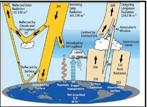
Naturally greenhouse gases exist in the atmosphere and have a key role in maintaining the energy balance on earth, by absorbing and reflecting radiation back to the Earth’s surface (Figure 1.3), a concept that is widely known as the greenhouse effect. The excessive greenhouse gases emission due to the anthropogenic activity, which
20 includes CO2, methane, nitrous oxide (N2O), Sulphur hexafluoride (SF6),
chlorofluorocarbons (CFCs) and hydrochlorofluorocarbons (HCFCs) have led to an enhanced greenhouse effect, whereby increased levels of radiation are trapped in the Earth’s atmosphere.
Figure 1.3.The global annual mean Earth’s energy budget for the March 2000 to May 2004 period (W m–2). The broad arrows indicate the schematic flow of energy in proportion to their
importance [7].
This is the principal cause in the increment of global average temperature, decrement in pH of the ocean surface and significant change to local weather systems: collectivity know as global climate change.
One of the first significant efforts reported in order to solve this problem was carried out by the United Nations Framework Convention of Climate Change (UNFCC) in 1997, through the sign of the “Kyoto Protocol”, which principal objective is to reduce greenhouse gas emissions. From that, carbon dioxide emissions from fossil fuel combustion are believed to be the most significant contributor to global climate change (figure 1.4).
21
Figure 1.4. World consumption (2015) in Million tonnes oil equivalent of the energy sources [6].
As mentioned before methane is also a greenhouse gas which contributes to global warming phenomena. Despite methane does not linger as long in the atmosphere as carbon dioxide, it is initially far more devastating to the climate because of how effectively it absorbs heat. In the first two decades after its release, methane is 84 times more potent than carbon dioxide. Both types of emissions must be addressed if we want to effectively reduce the impact of climate change [8]. About 25 % of the manmade global warming we are experiencing today is caused by methane emissions.
22
Figure 1.5. Global methane budget in millions of tons of CH4 per year [9].
In figure 1.5 is presented a diagram which shows the main sources of methane emissions into the atmosphere. In orange, those of anthropic origin and in green, those of natural origins. Natural emissions, fossil fuels, biomass burning, wetlands and agriculture and waste account respectively for 64, 105, 34, 167 and 188 million tons per year. Agriculture and waste are then responsible for the major part of methane emissions. Anyway, this methane can be used as a source of renewable energy thus reducing the impact of its environmental impact, the following section describes some current technologies for the processing of methane from waste and agriculture in general.
1.3.1. Biogas
Naturally the organic matter has an anaerobic decay what formed an important renewable source of methane. The methane obtained from these processes is usually called biogas. Almost all organic matter can be used as a biogas feedstock. The use of waste products could be particularly advantageous as it could prevent the unnecessary waste of useful energy sources and offer increased financial profits to plant operators. Industries that generate biogas from waste products could use it directly on-site as a fuel and/or for electricity generation [10]. Waste biomass that have potential for industrial biogas generation include:
23
Food waste – Waste materials from food processing industries, agricultural
processes and forestries all have the potential to generate biogas through the use of anaerobic digesters. In the U.K, several plants of this type are in operation including the use of brewery by-products, potato peelings, fish waste, sugar cane waste and other food wastes from kitchens [11].
Wastewater treatment – the sludge generated by the treatment of wastewater has to be chemically treated and disposed of, in a process that represents a considerable financial cost. One encouraging alternative is the generation of the biogas from wastewater sludge in anaerobic digestion tanks. This process has been considered economically feasible [10], this kind of processes are already operated in several sites across the U.K.
Animal manure – One important source of biogas is the manure which has
important uses in farming as a fertiliser, and recently also as a source for biogas generation on farm. The usual practice is to store the manure for several months until it is needed. During this time, gases that are produced from the manure can be released straight into the atmosphere, if they are not properly collected. To make use of these gases, the manure can be transferred to an anaerobic digester for biogas generation. The remaining substrate after biogas production still contains nutrients that give it value as a fertiliser [12].
Landfill gas – the organic fraction of municipal solid waste in landfill sites is
biologically digested by microorganisms, releasing a stream of methane-rich gas. Currently, landfill gas is often flared to prevent a risk of explosion on mixing with oxygen. Collection of this gas and subsequent use for energetic purposes could be a viable alternative [12], [13]. Challenges associated with landfill gas collection include inconsistent gas pressure and variable gas composition resulting from differences in local ecosystems within the landfill, as a result of the heterogeneous nature of the waste.
Other methods for biogas generation include the collection of biogas from large-scale cultivation of algae [14] and the growth and subsequent anaerobic digestion of dedicated energy crops such as rape. The latter method is more controversial as it
24 requires the occupation of land that could otherwise be used for growing food as well as substantial energy expenditure associated with the farming of these crops [11].
Combustion of renewable methane sources can emit CO2, but it is more favorable than
fossil fuel combustion. This is possible because the carbon in biogas was originally absorbed from the atmosphere by plants during photosynthesis. After, the same amount of carbon is returned to the atmosphere during combustion of the plant-derived fuel; therefore no additional carbon is introduced into the Earth’s carbon cycle. Thus maintaining null contribution to the feeding of the amounts of carbon dioxide in the atmosphere and the fuel can be considered carbon-neutral. This is in contrast to combustion of fossil fuels where carbon that has been removed from the carbon cycle for millions of years is reintroduced without an efficient removal mechanism.
Anyway, a renewed interest in gas-to-liquid processes has been initiated by the increasing legislation for cleaner energy sources, which includes the production of liquid fuels from biomass-derived sources. Another reason for interest in these reactions comes from the natural gas industry, where gas-to-liquid conversions, if carried out at remote offshore locations could enable some governments to profit from stranded natural gas reserves at oil wells where the natural gas by-product is otherwise flared [11]. There is little economic interest in transporting gas from remote locations due to the low volumetric energy content of natural gas compared with liquid oil [15], [16]. This because natural gas is transported from several countries after liquefaction, by cooling to -162 °C at atmospheric pressure. It is then reheated to recover the gas when it reaches the destination. However, this is an expensive solution and it does not address the need for sustainable sources of energy.
1.4. Fischer-Tropsch processes
The Fischer-Tropsch process was established in 1923 by German researchers, Franz Fischer and Hans Tropsch. They discovered that syngas CO + H2 could be converted
into a mixture of linear and branched hydrocarbons and alcohols using various metal catalysts at elevated temperatures. For commercial F-T synthesis, iron and cobalt catalysts are used at temperatures of 200 – 300 °C and pressures of 1000 – 6000 kPa. A syngas ratio of H2/CO = 2 is generally required. Potassium and iron catalysts are
25 used to promote the water-gas shift reaction which is used to modify the H2/CO ratio
[11]. The main reactions are shown in table 1.1.
Table 1.1. Main reactions in the Fischer-Tropsch synthesis, where n, x and y are integers and M represents a metal catalyst [17]
The main reactions
1. Alkanes (2n +1) H2 + n CO → CnH2n+2 + n H2O 2. Alkenes 2n H2 + n CO → CnH2n + n H2O 3. Water-gas shift CO + H2O ↔ CO2 + H2 Side reactions 4. Alcohols 2n H2 + n CO → CnH2n+2O + (n -1) H2O 5. Boudouard reaction 2 CO → C + CO2 Catalyst Modifications 6. Catalyst oxidation x M + y O2 ↔ MxO2y 7. Catalyst reduction MxOy + y H2 ↔ y H2O + x M 8. Bulk carbide formation y C + x M ↔ MxCy
Conventional refinery processes are used to separate and upgrade the syncrude mixture into useful products such as diesel, kerosene, naphtha and waxes. High quality liquid fuels can be produced by this method with very low aromaticity and zero sulphur impurities [17]. F-T processes are a well-established set of reactions that have been improved greatly over the years with advances in catalysis and reactor design.
26
Figure 1.6. Selectivity control in Fisher-Tropsch synthesis by process conditions and catalyst modifications [18].
The Fisher –Tropsch synthesis is a complex process In which a variety of variables can be operated for the purpose of increasing the selectivities of different products or conversions in the same system. Figure 1.6 presents the general influence of the main variables of the process on the selectivities and conversions of the system, which leaves evidence of its versatility and complexity.
However, further breakthroughs are necessary if the large scale manufacture of liquid fuels from biomass sources is to become viable for “today’s energy” markets [19]. Specific challenges arises from the high cost of syngas production and preparation including sulphur removal, partial oxidation or steam reforming of methane, heat recovery and the cooling of syngas; these processes have been estimated to induce 66 % of the total costs of the production of liquid fuels from natural gas [20].
Natural gas is becoming a new promising resource to replace petroleum oil. Currently there is a large amount of information related to the use of methane for different
27 purposes and this continues to increase. One field of this knowledge and maybe the most challenging, is the direct conversion of methane to liquid chemicals.
Methanol is a major raw material for petrochemical production and is currently under consideration as the principal liquid fuel [21]. In the past, the methanol was produced catalytically by the reaction of hydrogen and carbon monoxide at high pressure (≈20 bar) and high temperature (≈200 °C).
Many attempts have been made to produce methanol directly from methane [22]. Recently, some studies are still carried out in producing methanol from methane by plasma. Actually most of the research studies are focused on finding the best catalyst to improve the yields of methanol [23-25].
This combustible actually has great demand because it serves like an intermediate clean renewable source of energy of our daily life, for example: space heating, automobiles, fuel cell, and electric power generation.
Probably the most common and developed use is the environmental friendly replacement for methyl tertiary butyl ether (MTBE) in the transportation sector used as an additive in petroleum in order to increase the oxygen content of reactants. Therefore, methanol could prove to be a major fuel for the twenty first century [26].
1.5. Industrial methanol synthesis
Actually, methanol is manufactured by a two-step method, which means that it is necessary to begin with synthesis gas (syngas which is produced from methane).
𝐶𝐻4+ 𝐻2𝑂 → 𝐶𝑂 + 3𝐻2 𝛥𝐻𝑂 = 206 𝑘𝐽/𝑚𝑜𝑙 [Rxn 1.1]
𝐶𝐻4+ ½𝑂2 → 𝐶𝑂 + 2𝐻2 𝛥𝐻𝑂 = −36 𝑘𝐽/𝑚𝑜𝑙 [Rxn 1.2]
Then, methanol synthesis from syngas. This process is called indirect routes.
𝐶𝑂 + 2𝐻2 → 𝐶𝐻3𝑂𝐻 𝛥𝐻𝑂 = −90.6 𝑘𝐽/𝑚𝑜𝑙 [Rxn 1.3]
𝐶𝑂2+ 3𝐻2 → 𝐶𝐻3𝑂𝐻 + 𝐻2𝑂 𝛥𝐻𝑂 = −49.5 𝑘𝐽/𝑚𝑜𝑙 [Rxn 1.4]
28 As the first reaction is highly endothermic, the process suffers from high cost and thermal insufficiencies. The second process is an exothermic reaction and needs copper as a catalyst. The synthesis reactor is usually operated at the condition of high temperature and high pressure to achieve high yields of methanol. On the other hand, this environment tends to shorten the lifetime of the catalyst due to sintering of the active metal on the surface of the catalyst.
Due to the fact that the commercial methanol synthesis process is energetically demanding, it may not be more economical when the natural gas could be utilized directly. Therefore, a desirable alternative could be the direct partial oxidation of methane to methanol since a one-step process could potentially reduce both capital and operational costs. Meanwhile, an increasing number of applications and manufacturing processes that require methanol in much smaller quantities or methanol mobile-plans for example fuel cell applications [27], would deliver a strong message about the importance of methanol-based process in the future. Compared to hydrogen, methanol fuel is safer and easier to handle. A comprehensive review of this comparison has been done by Olah [28]. Developing new techniques and processes of direct conversion of methane to methanol is becoming a challenging research subject. Among other methods and techniques, non-thermal plasma chemical process is one of the most promising technologies in synthesizing methanol.
1.6. Introduction to plasma
Plasma is an ionized gas, a distinct fourth state of matter. The term “ionized” means that at least one electron is not bound to an atom or molecule, converting this atoms or molecules into positively charged ions. When energy is applied to a substance, the molecules become more energetic and transform through four distinct states of matter: solid, liquid, gas and finally plasma. Generally, this increased energetic state is associated with heating, however, plasma can also be generated from a gas by the application of an electric field, energetic beam or by adiabatic gas compression [29]. Under these conditions of increased energy, the gas molecules can become dissociated or ionized. This results in a complex mixture of freely moving charged particles and neutral gas species, sufficient to make the plasma electrically conductive,
29 a property that distinguishes plasma from neutral gas which is an electrical insulator. Approximately equal concentrations of positive ions and electrons make the plasma quasi-neutral.
Plasma is naturally abundant throughout the universe and comprises ~ 99 % of the observable cosmos, including the solar corona, solar wind and nebula [29], [30]. Plasma is also present in the upper region of the Earth’s atmosphere (at altitudes higher than 100 km) where interactions with cosmic radiation lead to the dissociation of atmospheric gas molecules. This produces a region of ions and freely moving electrons, known as the ionosphere. Plasmas can be visible on Earth as naturally occurring phenomena including lightning, the Aurora Borealis and the Aurora Australis [29].
1.6.1. Applications of plasma
The innovative studies of Siemens in the 1850s led to the first important industrial application of plasma in order to obtain ozone (O3) from oxygen using a silent
discharge, the ozone obtained was destined for water purification. Anyway, the first investigations into electrical arcs which involves several laboratory techniques have been developed for the generation of man-made plasma discharges since the early 19th century century [31].
However, Langmuir named this phenomenon as a “plasma” until the 1920s [32]. In recent years, plasma technologies have progressed to include a wide range of applications across many industries. Some important applications are listed below:
Surface modification, etching of semiconductors, “plasma hardening” of metallic
components for cars and aircrafts [30].
Thin film deposition, deposition of diamond and cubic boron nitride films for cutting tools [33], anti-reflective coatings for lenses, hydrophilic and hydrophobic coatings for textiles [30].
Pollutant remediation, destruction of odorous molecules and volatile organic compounds (VOCs) from diesel exhausts and flue gases [31], destruction of odorous molecules [34].
30 Lighting, excimer based UV and fluorescent lamps [31].
Plasma display panels, large area flat-screen televisions [35].
Lasers, CO2 laser discharges for cutting and welding [35].
Biomedical techniques, blood coagulation, desactivation of micro-organism, tissue engineering, sterilisation of instruments and surfaces [29].
Several of these plasma technologies are relatively developed. However, the empirical approach has focused on the production of deliverables, which leads to limited knowledge and understanding of plasma chemistry [30].
1.6.2. Types of plasma
All plasmas consist of multiple components including electrons, excited molecules and atoms, ions, radicals, neutral gas species and photons. There are two main types of plasmas: high-temperature plasma (such as thermonuclear fusion plasmas or thermal arc torches) and low-temperature plasma. The extent to which these constituents have reached thermal equilibrium is used to further classify the plasma as thermal or non-thermal (which are also known as equilibrium and non-equilibrium plasmas respectively). These classifications are shown in Table 1.2.
Table 1.2. Subdivision of plasmas by temperature, where T0 = gas temperature, Ti = ion
temperature, Tr = rotational temperature, Tv = vibrational temperature and Te = electron
temperature (Hippler et al., 2001).
Low-Temperature Plasma High Temperature Plasma
Non-Thermal Plasma Thermal Plasma T0 ≈ Ti ≈ Tr < Tv << Te ≤ 105 K T0 ≈ Ti ≈ Tr ≈ Tv ≈ Te ≤ 2 × 10⁴ K T0 ≈ Ti ≈ Tr ≈ Tv ≈ Te ≥ 107 K
In thermal plasma, sufficient applied energy and time for equilibration has resulted in a plasma discharge that can be defined by a single temperature. In the other hand, non-thermal plasmas are characterised by multiple temperatures relating to different plasma species. Electrons with high energetic values (103 – 105 K) can exist together
31 neutral molecules. Heavy gas molecules usually exhibit the lowest temperatures in these systems and in many cases the bulk gas remains close to room temperature [29].
1.6.3. Generation of non-thermal plasma by electric fields
The most used method for the formation of non-thermal plasma is by the application of an external electric field between two electrodes surrounded by a volume of gas. The plasma can be operated either at low pressures (10-3 Pa) or at atmospheric pressure
and above.
The breakdown voltage (Vb) defines the minimum voltage required to breakdown a gas
(or mixture of gases) to form a plasma discharge. Vb is dependent on the gas pressure
(p) and the distance between the electrodes (d). This relationship is described by Law of Paschen, where a and b are constants that are dependent on the gas type [36].
𝐕𝐛= 𝐥𝐧(𝐩 𝐝)+𝐛𝐚 𝐩 𝐝 e Eq. 1.1
An applied voltage causes free electrons that exist to some extent in a gas volume as a result of an interaction with cosmic radiation, to become accelerated. At the point where the breakdown voltage is reached, the current flow will increase sharply due to an intensive avalanche of electrons in the discharge gap between the electrodes. These high energy electrons will collide with gas molecules leading to the formation of new “active” plasma species including excited molecules and atoms and their relevant degrees of freedom, radicals, ions and new stable gas molecules. These collision processes are shown in Table 1.3.
32
Table 1.3. The main plasma processes. A and B represent atoms and M stands for a temporary collision partner [31]. Electron/Molecular Reactions Excitation Dissociation Attachment Dissociative attachment Ionisation Dissociative ionisation Recombination Detachment e- + A2 → A2* + e- e- + A2 → 2 A + e- e- + A2 → A2- e- + A2 → A- + A e- + A2 → A2+ + 2 e- e- + A2 → A+ + A + e- e- + A2+ → A2 e- + A2- → A2 + 2 e- Atomic/Molecular Reactions Penning dissociation Penning ionisation Charge transfer Ion recombination Neutral recombination M + A2 → 2 A + M M* + A2 → A2+ + M + e- A± + B → B± + A A- + B+ → AB A + B + M → AB + M Decomposition Electronic Atomic e- + AB → A + B + e- A* + B2 → AB + B Synthesis Electronic Atomic e- + A → A* + e-, A* + B → AB A + B → AB
During collisions between electrons and heavy gas molecules only a small portion of the energy is transferred, due to the relative sizes of the species involved. In most non-thermal plasma systems applied for gas processing, the pressure is the atmospheric one and the plasma is only weakly ionised. The degree of ionisation in the plasma can be defined as the ratio of the density of charged particles to the density of neutral species [29].
In addition to the plasma species shown in table 1.3, photons are also generated in the plasma volume. In an electronically excited gas molecule or atom, an electron
33 exists in a high energy orbital further from the nucleus, whilst an electron “hole” exists in the lower energy orbital that it was originally excited from. This excited state is metastable and can spontaneously return to its more stable ground state. When an electron is excited back to its lower energy orbital, the excess of energy is released in the form of a photon. This initiates a chain of reactive photon absorptions and emissions as molecules are excited and de-excited within the plasma. Consequently, the plasma can exhibit a visible glow if the energies of the emitted photons are in the visible region of the electromagnetic spectrum.
In plasma processing of gases, each of the plasma species may have different roles in the plasma chemistry. Electrons, being the first to receive energy from the electric field, distribute this energy through collisions, generating new reactive species. Vibrationally excited molecular states can transfer a significant proportion of energy into gas heating, which will accelerate chemical reactions in the plasma. Ions and radicals are able to make a significant contribution in plasma chemical synthesis due to their ability to react in plasma at lower temperatures than would be required by thermal reaction methods. Control over the complex chemical processes in a plasma by selection of appropriate gases, plasma type and operating conditions could allow the selective synthesis of the desired end products[29].
1.6.4. Townsend mechanism of electric breakdown
Consider breakdown in a plane gap d by DC voltage V corresponding to electric field
𝑬 = 𝑽𝒅 Eq. 1.2
Occasional primary electrons near a cathode provide low initial current i0. The primary
electrons drift the anode, ionizing the gas and generating avalanches. The ionization production of electrons per unit length along the electric field: dnc/ dx = αne, ne(x) = ne0
exp (αx). The Townsend ionization coefficient is related to the ionization rate coefficient ki (E/n0) and electron drift velocity vd as
𝜶 = 𝒗𝒊 𝒗𝒅= 𝟏 𝒗𝒅 𝒌𝒊( 𝑬 𝒏𝟎) 𝒏𝟎= 𝟏 𝝁𝒆 𝒌𝒊 (𝒏𝟎𝑬) 𝑬/𝒏𝟎 Eq. 1.3
Where vi is the ionization frequency and µe is electron mobility, which is inversely
34 parameter α/p depending on the reduced electric field E/p. Dependences α/p = f (E/p) for different gases can be found in Fridman and Kennedy [36].
Each primary electron generated near a cathode produces exp (αd) -1 positive ions moving back to the cathode. The ions lead to extraction of y* [exp (αd)-1] electrons from the cathode due to secondary electron emission characterized by the Townsend coefficient y. Typical y- values in discharges are 0.01-0.1. Taking into account the current of primary electrons i0 and electron current due to the secondary electron
emission from the cathode, the total electronic part of the cathode current icath is
𝒊𝒄𝒂𝒕𝒉 = 𝒊𝟎+ 𝒚𝒊𝒄𝒂𝒕𝒉⌈𝐞𝐱𝐩(𝜶𝒅) − 𝟏⌉ Eq. 1.4
Total current in the external circuit is equal to the electronic current at the anode, where the ion current is absent. The total current can be found as i=icath exp (αd), which leads
to the Townsend formula:
𝒊 = 𝒊𝟎𝐞𝐱𝐩(𝜶𝒅)
𝟏−𝒚[𝐞𝐱𝐩(𝜶𝒅)−𝟏] Eq. 1.5
The current in the gap is non-self-sustained as long as the denominator in Eq.1.5 is positive. When the electric field and Townsend coefficient α become high enough, the denominator in Eq. 1.5 goes to zero and transition to self-sustained current takes place, which is called the Townsend breakdown mechanism:
𝒚[𝐞𝐱𝐩(𝜶𝒅) − 𝟏 = 𝟏, 𝜶𝒅 = 𝐥𝐧 (𝟏𝒚+ 𝟏) Eq. 1.6
The similarity parameters α/p and E/p are related semi-empirically according to (Eq.1.3) as
𝜶
𝒑= 𝑨 𝐞𝐱𝐩 ( 𝑩
𝑬/𝒑) Eq. 1.7
Where parameters A and B are constants wich depend of gas nature usually founded at E/p =30-500 (V/cm*Torr) range.
Combination of relations (Eq.1.6) and (Eq.1.7) gives formulas for calculating the breakdown voltage and breakdown reduced electric field as functions of an important similarity parameter pd:
𝑽 = 𝑪+𝐥𝐧(𝒑𝒅)𝑩(𝒑𝒅) , 𝑬𝑷= 𝑪+𝐥𝐧(𝒑𝒅)𝑩 Eq. 1.8
35 dependence on the similarity parameter pd is usually referred to as the Paschen curve. These curves have a minimum corresponding to easier breakdown conditions, which can be found from (Eq.1.8):
𝑽𝒎𝒊𝒏 = 𝟐.𝟕𝟐∙𝑩𝑨 𝐥𝐧 (𝟏 +𝟏𝒚) , (𝑬𝒑) 𝒎𝒊𝒏 = 𝑩 , (𝒑𝒅)𝒎𝒊𝒏= 𝟐.𝟕𝟐 𝑨 𝐥𝐧 (𝟏 + 𝟏 𝒚) Eq. 1.9
Reduced electric field E/p required for breakdown (Eq.1.8) decreases only logarithmically with pd. Breakdown of larger gaps is less sensitive to the secondary electron emission and cathode material, which explains the E/p reduction with pd. This reduction of breakdown electric field in electronegative gases is limited by electron attachment processes, characterized by Townsend coefficient β:
𝜷 = 𝒗𝒂 𝒗𝒃= 𝟏 𝒗𝒅𝒌𝒂( 𝑬 𝒏𝟎) 𝒏𝟎= 𝟏 𝝁𝒆 𝒌𝒂 (𝑬/𝒏𝟎) 𝑬/𝒏𝟎 Eq. 1.10
In this relation ka(E/no) and va are the attachment rate coefficient and frequency with
respect to an electron. The Townsend coefficient β characterizes electron losses due to attachment per unit length:
𝒅𝒏𝒄
𝒅𝒙 = (𝜶 − 𝜷)𝒏𝒄, 𝒏𝒄(𝒙) = 𝒏𝒆𝑶𝐞𝐱𝐩⌊(𝜶 − 𝜷)𝒙⌋ Eq. 1.11
The Townsend coefficient β, similarly to α, is an exponential function of the reduced electric field although not as strong. Therefore, the ionization rate much exceeds attachment at high electric fields, and the coefficient β can be neglected with respect to α in this case. When the gaps are relatively large (≥ 1 cm at 1 atm), the Townsend breakdown electric fields in electronegative gases become almost constant and limited by attachment processes.
Several different types of non-thermal plasma can be formed depending on the type of applied electric field used to drive the plasma formation. This may be a continuous or pulsed direct current (DC) or an alternating current (AC) which may utilise radio frequencies (kHz – MHz) or microwave frequencies (GHz).
1.6.5. Continuous and pulsed direct current discharges
Several types of direct current (DC) discharge can be obtained depending on the voltage-current characteristics as depicted in figure 1.7. The initial breakdown of a gas at low current is known as a Townsend discharge. The transition from Townsend discharge to corona, through to subnormal glow discharge and normal glow discharge
36 is accompanied by an increase in current and simultaneous decrease in the applied voltage. A normal glow discharge can be characterised by a constant current density at the cathode surface, which is only partially covered by the discharge. As the current is increased with increasing voltage, an abnormal glow discharge develops which completely covers the cathode surface. At even higher currents, an irreversible glow-to-arc transition can occur. The arc is sustainable at low voltage and high current due to heating of the cathode to the point of thermionic emission (heat-induced current flow) [37].
Figure 1.7. The dependence of voltage upon current for various kinds of DC discharges [38].
The most used DC discharges in plasma processing of gases are the corona discharge and the gliding arc discharge, typical reactor configurations for these are described in the following sections [11].
1.6.5.1. Corona discharges
37 sharp points, edges, or thin wires where the electric field is sufficiently large, the corona discharge are always non uniform: a strong electric field, ionization and luminosity are located in the vicinity of one electrode. Charged particles are dragged by the weak electric fields from one electrode to another to close the electric circuit (the electric field at one or both electrodes is stronger than in the surrounding gas) [29]. A corona discharge can be formed by applying either continuous or pulsed DC voltage between two electrodes. The electrodes are most commonly arranged as a grounded cylindrical outer electrode (stainless steel tube) with a high voltage wire or rod inner electrode (Figure 1.8) or as a point-to-plate (Figure 1.9) or point-to-point electrode configuration. The area between the electrodes where the corona is formed is occupied by a continuous flow of gas.
Figure 1.8. Schematic diagram of a corona discharge reactor in a coaxial wire-cylinder configuration [11].
Figure 1.9. Schematic diagram of a corona discharge reactor in a point-to-plate configuration [11].
38 electrodes. The polarity electrode where the high electric field is located distinguish between negative corona (around the cathode) and positive corona (around the anode) [29]. For a point-to-plate electrode configuration, the different types of corona discharge are shown in Figure 1.10, where the applied voltage increases from left to right. Positive corona is formed at a pointed anode, whilst negative corona is formed at a pointed cathode. In a positive corona, the initial breakdown of the gas produces a burst pulse, which is limited to the area immediately surrounding the electrode. The discharge is space-charge limited and therefore requires an increase in voltage to create additional charged species, leading to the formation of streamers. Streamers extend into the inter-electrode gap and several transient streamers can be observed at a given time. In this mode, the corona occupies a relatively large active volume and has a low temperature of ~ 27 °C [39].
Figure 1.10. Schematic diagrams showing different forms of corona discharges in a point-to-plate electrode configuration [11].
In both positive and negative corona, high current flow will result in complete breakdown and the formation of a single spark discharge that bridges the discharge
39 gap. A spark discharge is confined to a narrow channel and produces an unsteady current. The spark is usually noisy and causes local heating in the channel in which it is formed and is therefore not a desirable outcome. The use of short DC pulses, typically of nanosecond duration can overcome the problem of unwanted spark formation. By varying between plasma pulses and plasma afterglow, the current flow can be controlled. This can improve the energy efficiency of the process and allow operation at higher powers [37].
1.6.5.2. Gliding arc discharges
A gliding arc is an auto-oscillating discharge between at least two diverging electrodes submerged in gas flow. Self-initiated in the upstream narrowest gap, the discharge forms the plasma column connecting the electrodes. This column is dragged by the gas flow toward the diverging downstream section. The arc grows with the increase interelectrode distance until it extinguishes, bit it reignites itself at the minimum distance between the electrodes to start a new cycle as shown in Figure 1.11 [29].
Figure 1.11. Schematic diagram of a gliding arc discharge reactor [11].
Gliding arcs may be thermal or non-thermal, depending on the applied power and gas flow rate. It is also possible to operate in the transitional regime, whereby the discharge has thermal characteristics in the lower part of the gliding-arc and evolves into a non-thermal discharge as it proceeds up the electrodes [29]. Gliding arc discharges are suitable for applications that require relatively large gas flows (several L min-1) and can
40 1.6.5.3. Dielectric barrier discharges (DBD)
The corona to spark transition is prevented in a pulsed corona by employing nanosecond pulse power supplies. Another approach which avoids spark formation in streamer channels is based on the use of a dielectric barrier in the discharge gap that stop current and prevent spark formation. Such a discharge is called the DBD. The presence of a dielectric barrier precludes DC operation of DBD, which usually operates at frequencies of 0.05-500 kHz. Sometimes DBDs are called the silent discharges due to the absence of the spark, which are accompanied by local overheating and the generation of local shock waves and noise.
The dielectric barrier discharge (DBD) or silent discharge (as it was originally known) is a strongly non-thermal plasma that can be operated at atmospheric pressure. DBDs are able to form stable discharges in a range of different gases at relatively high discharge powers, making them particularly suitable for many industrial applications. The DBD reactor consists of two electrodes with one or more dielectric barriers positioned in the discharge gap (in the path of current flow). Materials with high relative permittivity such as quartz, glass and ceramics are suitable for use as dielectric barriers. Several DBD configurations are possible including planar, cylindrical and surface discharges, as illustrated in Figure 1.12. The spacing in the discharge gap can vary from hundreds of micrometers to several centimeters.
41 1.6.5.3.1. Microdischarges
The term microdischarge is not clearly defined; sometimes it just indicates the generation of plasma smaller than 1 mm. According to such a definition, even DBD can be considered a microdischarge; the DBD gaps are often smaller than 1 mm, and the DBD filaments have a typical diameter of 0.1 mm [29].
The DBD is a non-uniform plasma discharge, it consists of many tiny breakdown channels known as microdischarges or filaments that cover the entire surface of the dielectric material and extend across the discharge gap. The dielectric barrier limits the flow of current causing the microdischarges to become extinguished, leaving significant charge deposition on the dielectric surfaces. As the polarity of the electrodes is rapidly changing, the microdischarges are reformed at the point where the breakdown voltage is reached in the next half cycle of the AC voltage sine wave. This results in the continuous formation of nanosecond microdischarges at a frequency which is twice that of the applied frequency [34]. The microdischarges appear as “spikes” on the current waveform. In appearance, the microdischarges are randomly distributed over the surface of the dielectric. In reality, the position of the microdischarge formation is dependent on the residual charge distribution on the dielectric surface [40], [41].
Where DBD plasmas are concerned, exclusive use of the term “dielectric constant” is used, but the terms “relative permittivity” and “dielectric constant” are synonymous, meaning the ability of a material to store electrical charge relative to a vacuum.
1.6.5.3.2. Memory effect in DBD plasma
The formation of the filaments is a complex process. Avalanches are first initiated, followed by cathode-oriented streamers bridging the gap. They form conducting channels of weakly ionized plasma until the local electric field is collapsed caused by the charges accumulated on the dielectric surface and ionic space charge. After electron current termination, there is still a high level of electronic excitation in the channel volume, along with charges deposited on the surface and ionic charges in the volume, allowing this region to be separated from the rest of the volume.
42 The fact that the remnant is not fully dissipated before the formation of the next microdischarge is called memory effect, which will facilitate the formation of a new filament in the same location. It is possible that with the increase in the flow rate value these remnant can displace through the channel and facilitate the appearance of discharge [42], [43].
1.7. Plasma chemistry for methanol production
There is currently promising research on the partial oxidation of methane in a non-thermal discharge, especially on DBD plasma. These experiments indicate that this kind of systems are able to create a highly reactive environment at low temperatures and therewith opens up an alternative, highly flexible and environmentally friendly processing route.
However, atmospheric pressure plasmas have a tendency to become unstable due to rapid transition to arcs. Confinement of high pressure plasma to dimensions below about one millimeter is useful to avoid instability problems and maintain a self-sustaining discharge. Such a plasma is often referred to as microplasma. In this respect, utilization of microplasma in microreaction technology can bring unconventional thermochemical conditions to materials processing, enabling better control over process parameters to selective synthesis of desirable products [44].
1.7.1. Plasma reactor designs for partial oxidation of methane (POM) Various designs of plasma reactor for methane and oxygen conversion to methanol have been proposed shown in Figure 1.13. The typical tubular discharge reactor consists of two concentric cylinders. The outer cylinder functions as ground electrode and the inner cylinder usually made from glass or quartz tube, serves as the dielectric. A steel or copper metal rod is located inside the inner cylinder and performs as another electrode. When plasma is turned on, the micro-discharges appear on the surface of the inside electrode.
43
Figure 1.13. Schematic diagram of the plasma DBD reactor a) [45], b) [46] c) [47]
The DBD plasma ability to reduce the required temperature and pressure needed for reactions to occur as well as its ability to control the products selectivity could be considered as a catalytic effect following the idea of Larkin et al. [48].
The partial oxidation of methane to methanol with oxygen or air was also investigated experimentally and theoretically by Zhou et., al. [47].
The reactor presented in figure 1.13c, consists in an annular discharge gap of 1 mm width formed by an outer steel cylinder of 54 mm inner diameter and an inserted cylindrical quartz tube of 52 mm outer diameter and 2.5 mm wall thickness. The length of the discharge gap is 310 mm, giving a discharge volume of about 50 ml. The outer steel cylinder serves as the ground electrode and an alternating sinusoidal high voltage of up to 20 kVpp amplitude and about 30 kHz frequency is applied to the HV electrode, a metal foil mounted inside of the quartz tube [47]. Is reported the partial oxidation of methane in two different types of reaction mixtures the first one consists in methane and oxygen and the second one in methane and air. The highest value of methanol yield of 3% was achieved in CH4/O2 (8/2) mixture. In CH4/O2 (7/3) mixtures 2% was
obtained.
a)
b)
c)
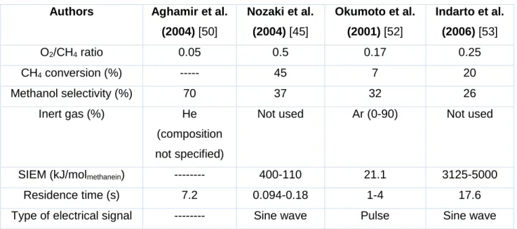
1 mm Discharge volume; 50 ml44 Another interesting reactor design was also proposed by Nozaki et al. (2004) [45], called micro-plasma reactor, shown in figure 1.13a. In their studies, the DBD reactor was used to synthesize methanol from methane and oxygen. It consists of a Pyrex thin glass tube with an internal diameter of 1.0 mm and a length equal to 60 mm, a twisted metallic wire inside the tube serves as electrode. The reactor is secured in a heat reservoir to maintain a constant reaction temperature. A high-voltage sine wave is applied between the twisted metallic wire and the grounded heat reservoir. The principle of generating plasma was similar to the DBD which was characterized by a variety of filamentary micro discharges. In this experiment, methanol was the major product, whose selectivity reached 34% at 30% of methane conversion. However, methanol, oxidized partially from methane, could further react to form other oxygenates such as formic acid and formaldehyde.
Another type of DBD reactor was proposed independently by Aghamir et al. (2004) and Okumoto et al. (1997) [49,50]. The general scheme of the reactor is presented in Figure 1.13b. The discharge reactor consisted of a 10 mm as an inner diameter quartz tube, which was also used as dielectric barrier. A stainless steel rod and a 15 cm long aluminum foil, formed respectively the anode and cathode of the discharge. The aluminum foil was tightly wrapped around the quartz tube, which had outer diameter of 12 mm. The stainless steel electrode was placed on the symmetric axis inside the tube. Two gas inlets located at the top and the bottom of the reactor were provided as an inlet of the reactants and an outlet of products [46]. C2 hydrocarbons and methanol
were mainly produced and the selectivity of methanol reached 30% with high voltage pulses of approximately 10-10 s of rise time, +25 kV of peak voltage, 440 Hz of pulse
45
Figure 1.14. Methanol selectivity behavior as a function of methane conversion reported in the literature [45], [46], [50], [51].
In figure 1.14 is presented the methanol selectivity as a function of the methane conversion. These results were reported by different authors who performed the partial oxidation of methane using a plasma DBD in a variety of working conditions. It can be noted that generally, the results are coherent as they follow the same tendency. The results of Mooday et al. and Nozaki et al. are however significantly different from the general trend.
A promising result finding in the literature were reported by Okumoto et al. (2007) [49] by using high voltage pulses in a mixture composed by methane, oxygen and argon they reported until 32 % of methanol selectivity at 8 % of methane conversion and 16 % of methanol selectivity at 30 % of methane conversion [46]. However, high values of methanol selectivity are present at low methane conversion values which results in low yields. Another interesting result were presented by Nozaki et al. (2004) using a sinusoidal signal. They reported until 37 % of methanol selectivity at 45 % of methane conversion [45], and it is one of the best results found in the literature on the subject. Apart from the reactor geometry, methane conversion and methanol formation can be affected by other parameters. The main parameters are the feed gas mixing ratio, residence time, applied voltage and inert gas. Those parameters have to be managed in order to achieve the optimum production of methanol.
0 5 10 15 20 25 30 35 40 0 10 20 30 40 50 60 Me th an o l s ele ctiv ity ( % n /n ) Methane conversion (% n/n)
![Figure 1.1.Proven world natural gas reserves by geographical region in 2015 [6] .](https://thumb-eu.123doks.com/thumbv2/123doknet/14669141.741390/19.892.171.724.729.1057/figure-proven-world-natural-gas-reserves-geographical-region.webp)
![Table 1.1. Main reactions in the Fischer-Tropsch synthesis, where n, x and y are integers and M represents a metal catalyst [17]](https://thumb-eu.123doks.com/thumbv2/123doknet/14669141.741390/26.892.153.742.253.743/table-reactions-fischer-tropsch-synthesis-integers-represents-catalyst.webp)
![Figure 1.7. The dependence of voltage upon current for various kinds of DC discharges [38]](https://thumb-eu.123doks.com/thumbv2/123doknet/14669141.741390/37.892.130.768.354.752/figure-dependence-voltage-current-various-kinds-dc-discharges.webp)
![Figure 1.9. Schematic diagram of a corona discharge reactor in a point-to-plate configuration [11]](https://thumb-eu.123doks.com/thumbv2/123doknet/14669141.741390/38.892.217.683.745.1008/figure-schematic-diagram-corona-discharge-reactor-point-configuration.webp)
![Figure 1.10. Schematic diagrams showing different forms of corona discharges in a point-to- point-to-plate electrode configuration [11]](https://thumb-eu.123doks.com/thumbv2/123doknet/14669141.741390/39.892.286.607.503.986/figure-schematic-diagrams-showing-different-discharges-electrode-configuration.webp)
![Figure 1.12. Schematic diagrams of planar, coaxial and surface DBD configurations [34]](https://thumb-eu.123doks.com/thumbv2/123doknet/14669141.741390/41.892.194.725.752.1085/figure-schematic-diagrams-planar-coaxial-surface-dbd-configurations.webp)
![Figure 2.2. Cross-section view of an image intensifier tube utilizes in a Princeton instrument ICCD camera [55]](https://thumb-eu.123doks.com/thumbv2/123doknet/14669141.741390/53.892.182.736.370.655/figure-cross-section-intensifier-utilizes-princeton-instrument-camera.webp)
