University Physics Volume 3
SENIOR CONTRIBUTING AUTHORS
S
AMUEL
J.
L
ING
,
T
RUMAN
S
TATE
U
NIVERSITY
J
EFF
S
ANNY
,
L
OYOLA
M
ARYMOUNT
U
NIVERSITY
OpenStax
Rice University
6100 Main Street MS-375 Houston, Texas 77005
To learn more about OpenStax, visit https://openstax.org.
Individual print copies and bulk orders can be purchased through our website.
©2018 Rice University. Textbook content produced by OpenStax is licensed under a Creative Commons Attribution 4.0
International License (CC BY 4.0). Under this license, any user of this textbook or the textbook contents herein must provide proper attribution as follows:
- If you redistribute this textbook in a digital format (including but not limited to PDF and HTML), then you must retain on every page the following attribution:
“Download for free at https://openstax.org/details/books/university-physics-volume-3.”
- If you redistribute this textbook in a print format, then you must include on every physical page the following attribution: “Download for free at https://openstax.org/details/books/university-physics-volume-3.”
- If you redistribute part of this textbook, then you must retain in every digital format page view (including but not limited to PDF and HTML) and on every physical printed page the following attribution:
“Download for free at https://openstax.org/details/books/university-physics-volume-3.”
- If you use this textbook as a bibliographic reference, please include https://openstax.org/details/books/university-physics-volume-3 in your citation.
For questions regarding this licensing, please contact [email protected].
Trademarks
The OpenStax name, OpenStax logo, OpenStax book covers, OpenStax CNX name, OpenStax CNX logo, OpenStax Tutor name, Openstax Tutor logo, Connexions name, Connexions logo, Rice University name, and Rice University logo are not subject to the license and may not be reproduced without the prior and express written consent of Rice University.
PRINT BOOK ISBN-10 1-938168-18-6 PRINT BOOK ISBN-13 978-1-938168-18-5 PDF VERSION ISBN-10 1-947172-22-0 PDF VERSION ISBN-13 978-1-947172-22-7 ENHANCED TEXTBOOK ISBN-10 1-947172-22-0 ENHANCED TEXTBOOK ISBN-13 978-1-947172-22-7 Revision Number UP3-2016-002(05/18)-MJ Original Publication Year 2016
OpenStax provides free, peer-reviewed, openly licensed textbooks for introductory college and Advanced Placement® courses and low-cost, personalized courseware that helps students learn. A nonprofit ed tech initiative based at Rice University, we’re committed to helping students access the tools they need to complete their courses and meet their educational goals.
RICE UNIVERSITY
OpenStax, OpenStax CNX, and OpenStax Tutor are initiatives of Rice University. As a leading research university with a distinctive commitment to undergraduate education, Rice University aspires to path-breaking research, unsurpassed teaching, and contributions to the betterment of our world. It seeks to fulfill this mission by cultivating a diverse community of learning and discovery that produces leaders across the spectrum of human endeavor.
FOUNDATION SUPPORT
OpenStax is grateful for the tremendous support of our sponsors. Without their strong engagement, the goal of free access to high-quality textbooks would remain just a dream.
Laura and John Arnold Foundation (LJAF) actively seeks opportunities to invest in organizations and thought leaders that have a sincere interest in implementing fundamental changes that not only yield immediate gains, but also repair broken systems for future generations. LJAF currently focuses its strategic investments on education, criminal justice, research integrity, and public accountability.
The William and Flora Hewlett Foundation has been making grants since 1967 to help solve social and environmental problems at home and around the world. The Foundation concentrates its resources on activities in education, the environment, global development and population, performing arts, and philanthropy, and makes grants to support disadvantaged communities in the San Francisco Bay Area.
Calvin K. Kazanjian was the founder and president of Peter Paul (Almond Joy), Inc. He firmly believed that the more people understood about basic economics the happier and more prosperous they would be. Accordingly, he established the Calvin K. Kazanjian Economics Foundation Inc, in 1949 as a philanthropic, nonpolitical educational organization to support efforts that enhanced economic understanding.
Guided by the belief that every life has equal value, the Bill & Melinda Gates Foundation works to help all people lead healthy, productive lives. In developing countries, it focuses on improving people’s health with vaccines and other life-saving tools and giving them the chance to lift themselves out of hunger and extreme poverty. In the United States, it seeks to significantly improve education so that all young people have the opportunity to reach their full potential. Based in Seattle, Washington, the foundation is led by CEO Jeff Raikes and Co-chair William H. Gates Sr., under the direction of Bill and Melinda Gates and Warren Buffett.
The Maxfield Foundation supports projects with potential for high impact in science, education, sustainability, and other areas of social importance.
Our mission at The Michelson 20MM Foundation is to grow access and success by eliminating unnecessary hurdles to affordability. We support the creation, sharing, and proliferation of more effective, more affordable educational content by leveraging disruptive technologies, open educational resources, and new models for collaboration between for-profit, nonprofit, and public entities.
The Bill and Stephanie Sick Fund supports innovative projects in the areas of Education, Art, Science and Engineering.
new school year.
new classes.
new books.
new assignments.
new app.
free books.
free app.
Get free textbooks for over 30
college courses in the free
OpenStax + SE app.
Download it now on the App Store
or get it on Google Play.
Chapter 1: The Nature of Light . . . 7
1.1 The Propagation of Light . . . 8
1.2 The Law of Reflection . . . 12
1.3 Refraction . . . 15
1.4 Total Internal Reflection . . . 19
1.5 Dispersion . . . 24
1.6 Huygens’s Principle . . . 28
1.7 Polarization . . . 33
Chapter 2: Geometric Optics and Image Formation . . . 53
2.1 Images Formed by Plane Mirrors . . . 54
2.2 Spherical Mirrors . . . 56
2.3 Images Formed by Refraction . . . 67
2.4 Thin Lenses . . . 70
2.5 The Eye . . . 82
2.6 The Camera . . . 89
2.7 The Simple Magnifier . . . 91
2.8 Microscopes and Telescopes . . . 94
Chapter 3: Interference . . . 117
3.1 Young's Double-Slit Interference . . . 117
3.2 Mathematics of Interference . . . 121
3.3 Multiple-Slit Interference . . . 124
3.4 Interference in Thin Films . . . 126
3.5 The Michelson Interferometer . . . 132
Chapter 4: Diffraction . . . 145
4.1 Single-Slit Diffraction . . . 146
4.2 Intensity in Single-Slit Diffraction . . . 150
4.3 Double-Slit Diffraction . . . 155
4.4 Diffraction Gratings . . . 157
4.5 Circular Apertures and Resolution . . . 162
4.6 X-Ray Diffraction . . . 168
4.7 Holography . . . 171
Unit 2. Modern Physics Chapter 5: Relativity . . . 185
5.1 Invariance of Physical Laws . . . 186
5.2 Relativity of Simultaneity . . . 188
5.3 Time Dilation . . . 191
5.4 Length Contraction . . . 201
5.5 The Lorentz Transformation . . . 206
5.6 Relativistic Velocity Transformation . . . 216
5.7 Doppler Effect for Light . . . 220
5.8 Relativistic Momentum . . . 223
5.9 Relativistic Energy . . . 225
Chapter 6: Photons and Matter Waves . . . 247
6.1 Blackbody Radiation . . . 248
6.2 Photoelectric Effect . . . 256
6.3 The Compton Effect . . . 262
6.4 Bohr’s Model of the Hydrogen Atom . . . 267
6.5 De Broglie’s Matter Waves . . . 277
6.6 Wave-Particle Duality . . . 285
Chapter 7: Quantum Mechanics . . . 303
7.1 Wave Functions . . . 304
7.2 The Heisenberg Uncertainty Principle . . . 315
7.3 The Schrӧdinger Equation . . . 318
7.4 The Quantum Particle in a Box . . . 321
8.1 The Hydrogen Atom . . . 356
8.2 Orbital Magnetic Dipole Moment of the Electron . . . 365
8.3 Electron Spin . . . 370
8.4 The Exclusion Principle and the Periodic Table . . . 374
8.5 Atomic Spectra and X-rays . . . 380
8.6 Lasers . . . 391
Chapter 9: Condensed Matter Physics . . . 403
9.1 Types of Molecular Bonds . . . 404
9.2 Molecular Spectra . . . 409
9.3 Bonding in Crystalline Solids . . . 412
9.4 Free Electron Model of Metals . . . 419
9.5 Band Theory of Solids . . . 424
9.6 Semiconductors and Doping . . . 427
9.7 Semiconductor Devices . . . 430
9.8 Superconductivity . . . 436
Chapter 10: Nuclear Physics . . . 453
10.1 Properties of Nuclei . . . 454
10.2 Nuclear Binding Energy . . . 459
10.3 Radioactive Decay . . . 462
10.4 Nuclear Reactions . . . 469
10.5 Fission . . . 477
10.6 Nuclear Fusion . . . 483
10.7 Medical Applications and Biological Effects of Nuclear Radiation . . . 488
Chapter 11: Particle Physics and Cosmology . . . 507
11.1 Introduction to Particle Physics . . . 508
11.2 Particle Conservation Laws . . . 512
11.3 Quarks . . . 517
11.4 Particle Accelerators and Detectors . . . 521
11.5 The Standard Model . . . 529
11.6 The Big Bang . . . 534
11.7 Evolution of the Early Universe . . . 538
Appendix A: Units . . . 555
Appendix B: Conversion Factors . . . 559
Appendix C: Fundamental Constants . . . 563
Appendix D: Astronomical Data . . . 565
Appendix E: Mathematical Formulas . . . 567
Appendix F: Chemistry . . . 571
Appendix G: The Greek Alphabet . . . 573
PREFACE
Welcome to University Physics, an OpenStax resource. This textbook was written to increase student access to high-quality learning materials, maintaining highest standards of academic rigor at little to no cost.
About OpenStax
OpenStax is a nonprofit based at Rice University, and it’s our mission to improve student access to education. Our first openly licensed college textbook was published in 2012 and our library has since scaled to over 25 books used by hundreds of thousands of students across the globe. OpenStax Tutor, our low-cost personalized learning tool, is being used in college courses throughout the country. The OpenStax mission is made possible through the generous support of philanthropic foundations. Through these partnerships and with the help of additional low-cost resources from our OpenStax partners, OpenStax is breaking down the most common barriers to learning and empowering students and instructors to succeed.
About OpenStax's resources
CustomizationUniversity Physics is licensed under a Creative Commons Attribution 4.0 International (CC BY) license, which means
that you can distribute, remix, and build upon the content, as long as you provide attribution to OpenStax and its content contributors.
Because our books are openly licensed, you are free to use the entire book or pick and choose the sections that are most relevant to the needs of your course. Feel free to remix the content by assigning your students certain chapters and sections in your syllabus in the order that you prefer. You can even provide a direct link in your syllabus to the sections in the web view of your book.
Instructors also have the option of creating a customized version of their OpenStax book. The custom version can be made available to students in low-cost print or digital form through their campus bookstore. Visit your book page on OpenStax.org for more information.
Errata
All OpenStax textbooks undergo a rigorous review process. However, like any professional-grade textbook, errors sometimes occur. Since our books are web based, we can make updates periodically when deemed pedagogically necessary. If you have a correction to suggest, submit it through the link on your book page on OpenStax.org. Subject matter experts review all errata suggestions. OpenStax is committed to remaining transparent about all updates, so you will also find a list of past errata changes on your book page on OpenStax.org.
Format
You can access this textbook for free in web view or PDF through OpenStax.org, and for a low cost in print.
About University Physics
University Physics is designed for the two- or three-semester calculus-based physics course. The text has been developed
to meet the scope and sequence of most university physics courses and provides a foundation for a career in mathematics, science, or engineering. The book provides an important opportunity for students to learn the core concepts of physics and understand how those concepts apply to their lives and to the world around them.
Due to the comprehensive nature of the material, we are offering the book in three volumes for flexibility and efficiency.
Coverage and scope
Our University Physics textbook adheres to the scope and sequence of most two- and three-semester physics courses nationwide. We have worked to make physics interesting and accessible to students while maintaining the mathematical rigor inherent in the subject. With this objective in mind, the content of this textbook has been developed and arranged to provide a logical progression from fundamental to more advanced concepts, building upon what students have already learned and emphasizing connections between topics and between theory and applications. The goal of each section is to enable students not just to recognize concepts, but to work with them in ways that will be useful in later courses and future careers. The organization and pedagogical features were developed and vetted with feedback from science educators dedicated to the project.
VOLUME I Unit 1: Mechanics
Chapter 1: Units and Measurement Chapter 2: Vectors
Chapter 3: Motion Along a Straight Line Chapter 4: Motion in Two and Three Dimensions Chapter 5: Newton’s Laws of Motion
Chapter 6: Applications of Newton’s Laws Chapter 7: Work and Kinetic Energy
Chapter 8: Potential Energy and Conservation of Energy Chapter 9: Linear Momentum and Collisions
Chapter 10: Fixed-Axis Rotation Chapter 11: Angular Momentum
Chapter 12: Static Equilibrium and Elasticity Chapter 13: Gravitation
Chapter 14: Fluid Mechanics Unit 2: Waves and Acoustics
Chapter 15: Oscillations Chapter 16: Waves Chapter 17: Sound VOLUME II
Unit 1: Thermodynamics
Chapter 1: Temperature and Heat Chapter 2: The Kinetic Theory of Gases Chapter 3: The First Law of Thermodynamics Chapter 4: The Second Law of Thermodynamics Unit 2: Electricity and Magnetism
Chapter 5: Electric Charges and Fields Chapter 6: Gauss’s Law
Chapter 7: Electric Potential Chapter 8: Capacitance
Chapter 9: Current and Resistance Chapter 10: Direct-Current Circuits Chapter 11: Magnetic Forces and Fields Chapter 12: Sources of Magnetic Fields Chapter 13: Electromagnetic Induction Chapter 14: Inductance
Chapter 15: Alternating-Current Circuits Chapter 16: Electromagnetic Waves
Chapter 2: Geometric Optics and Image Formation Chapter 3: Interference
Chapter 4: Diffraction Unit 2: Modern Physics
Chapter 5: Relativity
Chapter 6: Photons and Matter Waves Chapter 7: Quantum Mechanics Chapter 8: Atomic Structure
Chapter 9: Condensed Matter Physics Chapter 10: Nuclear Physics
Chapter 11: Particle Physics and Cosmology
Pedagogical foundation
Throughout University Physics you will find derivations of concepts that present classical ideas and techniques, as well as modern applications and methods. Most chapters start with observations or experiments that place the material in a context of physical experience. Presentations and explanations rely on years of classroom experience on the part of long-time physics professors, striving for a balance of clarity and rigor that has proven successful with their students. Throughout the text, links enable students to review earlier material and then return to the present discussion, reinforcing connections between topics. Key historical figures and experiments are discussed in the main text (rather than in boxes or sidebars), maintaining a focus on the development of physical intuition. Key ideas, definitions, and equations are highlighted in the text and listed in summary form at the end of each chapter. Examples and chapter-opening images often include contemporary applications from daily life or modern science and engineering that students can relate to, from smart phones to the internet to GPS devices.
Assessments that reinforce key concepts
In-chapter Examples generally follow a three-part format of Strategy, Solution, and Significance to emphasize how to approach a problem, how to work with the equations, and how to check and generalize the result. Examples are often followed by Check Your Understanding questions and answers to help reinforce for students the important ideas of the examples. Problem-Solving Strategies in each chapter break down methods of approaching various types of problems into steps students can follow for guidance. The book also includes exercises at the end of each chapter so students can practice what they’ve learned.
Conceptual questions do not require calculation but test student learning of the key concepts.
Problems categorized by section test student problem-solving skills and the ability to apply ideas to practical situations.
Additional Problems apply knowledge across the chapter, forcing students to identify what concepts and equations are appropriate for solving given problems. Randomly located throughout the problems are Unreasonable Results exercises that ask students to evaluate the answer to a problem and explain why it is not reasonable and what assumptions made might not be correct.
Challenge Problems extend text ideas to interesting but difficult situations. Answers for selected exercises are available in an Answer Key at the end of the book.
Additional resources
Student and instructor resourcesWe’ve compiled additional resources for both students and instructors, including Getting Started Guides, PowerPoint slides, and answer and solution guides for instructors and students. Instructor resources require a verified instructor account, which you can apply for when you log in or create your account on OpenStax.org. Take advantage of these resources to supplement your OpenStax book.
Community Hubs
OpenStax partners with the Institute for the Study of Knowledge Management in Education (ISKME) to offer Community Hubs on OER Commons – a platform for instructors to share community-created resources that support OpenStax books, free of charge. Through our Community Hubs, instructors can upload their own materials or download resources to use in their own courses, including additional ancillaries, teaching material, multimedia, and relevant course content. We
encourage instructors to join the hubs for the subjects most relevant to your teaching and research as an opportunity both to enrich your courses and to engage with other faculty.
To reach the Community Hubs, visit www.oercommons.org/hubs/OpenStax (https://www.oercommons.org/ hubs/OpenStax).
Partner resources
OpenStax partners are our allies in the mission to make high-quality learning materials affordable and accessible to students and instructors everywhere. Their tools integrate seamlessly with our OpenStax titles at a low cost. To access the partner resources for your text, visit your book page on OpenStax.org.
About the authors
Senior contributing authorsSamuel J. Ling, Truman State University
Dr. Samuel Ling has taught introductory and advanced physics for over 25 years at Truman State University, where he is currently Professor of Physics and the Department Chair. Dr. Ling has two PhDs from Boston University, one in Chemistry and the other in Physics, and he was a Research Fellow at the Indian Institute of Science, Bangalore, before joining Truman. Dr. Ling is also an author of A First Course in Vibrations and Waves, published by Oxford University Press. Dr. Ling has considerable experience with research in Physics Education and has published research on collaborative learning methods in physics teaching. He was awarded a Truman Fellow and a Jepson fellow in recognition of his innovative teaching methods. Dr. Ling’s research publications have spanned Cosmology, Solid State Physics, and Nonlinear Optics.
Jeff Sanny, Loyola Marymount University
Dr. Jeff Sanny earned a BS in Physics from Harvey Mudd College in 1974 and a PhD in Solid State Physics from the University of California–Los Angeles in 1980. He joined the faculty at Loyola Marymount University in the fall of 1980. During his tenure, he has served as department Chair as well as Associate Dean. Dr. Sanny enjoys teaching introductory physics in particular. He is also passionate about providing students with research experience and has directed an active undergraduate student research group in space physics for many years.
William Moebs, Formerly of Loyola Marymount University
Dr. William Moebs earned a BS and PhD (1959 and 1965) from the University of Michigan. He then joined their staff as a Research Associate for one year, where he continued his doctoral research in particle physics. In 1966, he accepted an appointment to the Physics Department of Indiana Purdue Fort Wayne (IPFW), where he served as Department Chair from 1971 to 1979. In 1979, he moved to Loyola Marymount University (LMU), where he served as Chair of the Physics Department from 1979 to 1986. He retired from LMU in 2000. He has published research in particle physics, chemical kinetics, cell division, atomic physics, and physics teaching.
Contributing authors
Stephen D. Druger
Alice Kolakowska, University of Memphis David Anderson, Albion College
Daniel Bowman, Ferrum College Dedra Demaree, Georgetown University Edw. S. Ginsberg, University of Massachusetts Joseph Trout, Richard Stockton College Kevin Wheelock, Bellevue College
David Smith, University of the Virgin Islands Takashi Sato, Kwantlen Polytechnic University Gerald Friedman, Santa Fe Community College Lev Gasparov, University of North Florida Lee LaRue, Paris Junior College
Mark Lattery, University of Wisconsin Richard Ludlow, Daniel Webster College Patrick Motl, Indiana University Kokomo Tao Pang, University of Nevada, Las Vegas Kenneth Podolak, Plattsburgh State University
Gavin Buxton, Robert Morris University Erik Christensen, South Florida State College Clifton Clark, Fort Hays State University Nelson Coates, California Maritime Academy Herve Collin, Kapi’olani Community College Carl Covatto, Arizona State University Alejandro Cozzani, Imperial Valley College Danielle Dalafave, The College of New Jersey Nicholas Darnton, Georgia Institute of Technology Ethan Deneault, University of Tampa
Kenneth DeNisco, Harrisburg Area Community College Robert Edmonds, Tarrant County College
William Falls, Erie Community College Stanley Forrester, Broward College Umesh Garg, University of Notre Dame Maurizio Giannotti, Barry University
Bryan Gibbs, Dallas County Community College Lynn Gillette, Pima Community College–West Campus Mark Giroux, East Tennessee State University
Matthew Griffiths, University of New Haven Alfonso Hinojosa, University of Texas–Arlington Steuard Jensen, Alma College
David Kagan, University of Massachusetts Sergei Katsev, University of Minnesota–Duluth Jill Leggett, Florida State College–Jacksonville Alfredo Louro, University of Calgary
James Maclaren, Tulane University
Ponn Maheswaranathan, Winthrop University Seth Major, Hamilton College
Oleg Maksimov, Excelsior College
Aristides Marcano, Delaware State University James McDonald, University of Hartford
Ralph McGrew, SUNY–Broome Community College Paul Miller, West Virginia University
Tamar More, University of Portland Farzaneh Najmabadi, University of Phoenix Richard Olenick, The University of Dallas Christopher Porter, Ohio State University Liza Pujji, Manakau Institute of Technology Baishali Ray, Young Harris University Andrew Robinson, Carleton University Aruvana Roy, Young Harris University Gajendra Tulsian, Daytona State College Adria Updike, Roger Williams University Clark Vangilder, Central Arizona University Steven Wolf, Texas State University
Alexander Wurm, Western New England University Lei Zhang, Winston Salem State University Ulrich Zurcher, Cleveland State University
1
|
THE NATURE OF LIGHT
Figure 1.1 Due to total internal reflection, an underwater swimmer’s image is reflected back into the water where the camera is located. The circular ripple in the image center is actually on the water surface. Due to the viewing angle, total internal reflection is not occurring at the top edge of this image, and we can see a view of activities on the pool deck. (credit: modification of work by “jayhem”/Flickr)
Chapter Outline
1.1The Propagation of Light
1.2The Law of Reflection
1.3Refraction
1.4Total Internal Reflection
1.5Dispersion
1.6Huygens’s Principle
1.7Polarization
Introduction
Our investigation of light revolves around two questions of fundamental importance: (1) What is the nature of light, and (2) how does light behave under various circumstances? Answers to these questions can be found in Maxwell’s equations (in
Electromagnetic Waves (http://cnx.org/content/m58495/latest/)), which predict the existence of electromagnetic waves and their behavior. Examples of light include radio and infrared waves, visible light, ultraviolet radiation, and X-rays. Interestingly, not all light phenomena can be explained by Maxwell’s theory. Experiments performed early in the twentieth century showed that light has corpuscular, or particle-like, properties. The idea that light can display both wave and particle characteristics is called wave-particle duality, which is examined inPhotons and Matter Waves.
In this chapter, we study the basic properties of light. In the next few chapters, we investigate the behavior of light when it interacts with optical devices such as mirrors, lenses, and apertures.
1.1
|
The Propagation of Light
Learning Objectives
By the end of this section, you will be able to:
• Determine the index of refraction, given the speed of light in a medium • List the ways in which light travels from a source to another location
The speed of light in a vacuum c is one of the fundamental constants of physics. As you will see when you reachRelativity, it is a central concept in Einstein’s theory of relativity. As the accuracy of the measurements of the speed of light improved, it was found that different observers, even those moving at large velocities with respect to each other, measure the same value for the speed of light. However, the speed of light does vary in a precise manner with the material it traverses. These facts have far-reaching implications, as we will see in later chapters.
The Speed of Light: Early Measurements
The first measurement of the speed of light was made by the Danish astronomer Ole Roemer (1644–1710) in 1675. He studied the orbit of Io, one of the four large moons of Jupiter, and found that it had a period of revolution of 42.5 h around Jupiter. He also discovered that this value fluctuated by a few seconds, depending on the position of Earth in its orbit around the Sun. Roemer realized that this fluctuation was due to the finite speed of light and could be used to determine c. Roemer found the period of revolution of Io by measuring the time interval between successive eclipses by Jupiter.Figure 1.2(a) shows the planetary configurations when such a measurement is made from Earth in the part of its orbit where it is receding from Jupiter. When Earth is at point A, Earth, Jupiter, and Io are aligned. The next time this alignment occurs, Earth is at point B, and the light carrying that information to Earth must travel to that point. Since B is farther from Jupiter than A, light takes more time to reach Earth when Earth is at B. Now imagine it is about 6 months later, and the planets are arranged as in part (b) of the figure. The measurement of Io’s period begins with Earth at point A′ and Io eclipsed by Jupiter. The next eclipse then occurs when Earth is at point B′, to which the light carrying the information of this eclipse must travel. Since B′ is closer to Jupiter than A′, light takes less time to reach Earth when it is at B′. This time interval between the successive eclipses of Io seen at A′ and B′ is therefore less than the time interval between the eclipses seen at A and B. By measuring the difference in these time intervals and with appropriate knowledge of the distance between Jupiter and Earth, Roemer calculated that the speed of light was 2.0 × 10⁸m/s, which is 33% below the value accepted today.
Figure 1.2 Roemer’s astronomical method for determining the speed of light. Measurements of Io’s period done with the configurations of parts (a) and (b) differ, because the light path length and associated travel time increase from A to B (a) but decrease from A′ to B′ (b).
The first successful terrestrial measurement of the speed of light was made by Armand Fizeau (1819–1896) in 1849. He placed a toothed wheel that could be rotated very rapidly on one hilltop and a mirror on a second hilltop 8 km away (Figure
while the pulses traveled down to the mirror and back. Knowing the rotational speed of the wheel, the number of teeth on the wheel, and the distance to the mirror, Fizeau determined the speed of light to be 3.15 × 10⁸m/s, which is only 5% too high.
Figure 1.3 Fizeau’s method for measuring the speed of light. The teeth of the wheel block the reflected light upon return when the wheel is rotated at a rate that matches the light travel time to and from the mirror.
The French physicist Jean Bernard Léon Foucault (1819–1868) modified Fizeau’s apparatus by replacing the toothed wheel with a rotating mirror. In 1862, he measured the speed of light to be 2.98 × 10⁸m/s, which is within 0.6% of the presently accepted value. Albert Michelson (1852–1931) also used Foucault’s method on several occasions to measure the speed of light. His first experiments were performed in 1878; by 1926, he had refined the technique so well that he found c to be
(2.99796 ± 4) × 108m/s.
Today, the speed of light is known to great precision. In fact, the speed of light in a vacuum c is so important that it is accepted as one of the basic physical quantities and has the value
(1.1)
c = 2.99792458 × 10⁸ m/s ≈ 3.00 × 10⁸ m/s
where the approximate value of 3.00 × 10⁸m/s is used whenever three-digit accuracy is sufficient.
Speed of Light in Matter
The speed of light through matter is less than it is in a vacuum, because light interacts with atoms in a material. The speed of light depends strongly on the type of material, since its interaction varies with different atoms, crystal lattices, and other substructures. We can define a constant of a material that describes the speed of light in it, called the index of refraction n:
(1.2)
n = cv
where v is the observed speed of light in the material.
Since the speed of light is always less than c in matter and equals c only in a vacuum, the index of refraction is always greater than or equal to one; that is, n ≥ 1.Table 1.1gives the indices of refraction for some representative substances. The values are listed for a particular wavelength of light, because they vary slightly with wavelength. (This can have
important effects, such as colors separated by a prism, as we will see inDispersion.) Note that for gases, n is close to 1.0. This seems reasonable, since atoms in gases are widely separated, and light travels at c in the vacuum between atoms. It is common to take n = 1 for gases unless great precision is needed. Although the speed of light v in a medium varies considerably from its value c in a vacuum, it is still a large speed.
Medium n Gases at 0°C, 1 atm Air 1.000293 Carbon dioxide 1.00045 Hydrogen 1.000139 Oxygen 1.000271 Liquids at 20°C Benzene 1.501 Carbon disulfide 1.628 Carbon tetrachloride 1.461 Ethanol 1.361 Glycerine 1.473 Water, fresh 1.333 Solids at 20°C Diamond 2.419 Fluorite 1.434 Glass, crown 1.52 Glass, flint 1.66 Ice (at 0°C) 1.309 Polystyrene 1.49 Plexiglas 1.51 Quartz, crystalline 1.544 Quartz, fused 1.458 Sodium chloride 1.544 Zircon 1.923
Table 1.1 Index of Refraction in Various Media For light with a wavelength of 589 nm in a vacuum
Example 1.1
Speed of Light in Jewelry
Calculate the speed of light in zircon, a material used in jewelry to imitate diamond.
1.1
Solution
Rearranging the equation n = c/v for v gives us
v = cn.
The index of refraction for zircon is given as 1.923 inTable 1.1, and c is given inEquation 1.1. Entering these values in the equation gives
v = 3.00 × 101.9238m/s= 1.56 × 10⁸ m/s.
Significance
This speed is slightly larger than half the speed of light in a vacuum and is still high compared with speeds we normally experience. The only substance listed inTable 1.1that has a greater index of refraction than zircon is diamond. We shall see later that the large index of refraction for zircon makes it sparkle more than glass, but less than diamond.
Check Your UnderstandingTable 1.1shows that ethanol and fresh water have very similar indices of refraction. By what percentage do the speeds of light in these liquids differ?
The Ray Model of Light
You have already studied some of the wave characteristics of light in the previous chapter onElectromagnetic Waves (http://cnx.org/content/m58495/latest/). In this chapter, we start mainly with the ray characteristics. There are three ways in which light can travel from a source to another location (Figure 1.4). It can come directly from the source through empty space, such as from the Sun to Earth. Or light can travel through various media, such as air and glass, to the observer. Light can also arrive after being reflected, such as by a mirror. In all of these cases, we can model the path of light as a straight line called a ray.
Figure 1.4 Three methods for light to travel from a source to another location. (a) Light reaches the upper atmosphere of Earth, traveling through empty space directly from the source. (b) Light can reach a person by traveling through media like air and glass. (c) Light can also reflect from an object like a mirror. In the situations shown here, light interacts with objects large enough that it travels in straight lines, like a ray.
Experiments show that when light interacts with an object several times larger than its wavelength, it travels in straight lines and acts like a ray. Its wave characteristics are not pronounced in such situations. Since the wavelength of visible light is less than a micron (a thousandth of a millimeter), it acts like a ray in the many common situations in which it encounters objects larger than a micron. For example, when visible light encounters anything large enough that we can observe it with unaided eyes, such as a coin, it acts like a ray, with generally negligible wave characteristics.
In all of these cases, we can model the path of light as straight lines. Light may change direction when it encounters objects (such as a mirror) or in passing from one material to another (such as in passing from air to glass), but it then continues in a straight line or as a ray. The word “ray” comes from mathematics and here means a straight line that originates at some
point. It is acceptable to visualize light rays as laser rays. The ray model of light describes the path of light as straight lines. Since light moves in straight lines, changing directions when it interacts with materials, its path is described by geometry and simple trigonometry. This part of optics, where the ray aspect of light dominates, is therefore called geometric optics. Two laws govern how light changes direction when it interacts with matter. These are the law of reflection, for situations in which light bounces off matter, and the law of refraction, for situations in which light passes through matter. We will examine more about each of these laws in upcoming sections of this chapter.
1.2
|
The Law of Reflection
Learning Objectives
By the end of this section, you will be able to:
• Explain the reflection of light from polished and rough surfaces • Describe the principle and applications of corner reflectors
Whenever we look into a mirror, or squint at sunlight glinting from a lake, we are seeing a reflection. When you look at a piece of white paper, you are seeing light scattered from it. Large telescopes use reflection to form an image of stars and other astronomical objects.
The law of reflection states that the angle of reflection equals the angle of incidence, or
(1.3)
θr= θi
The law of reflection is illustrated inFigure 1.5, which also shows how the angle of incidence and angle of reflection are measured relative to the perpendicular to the surface at the point where the light ray strikes.
Figure 1.5 The law of reflection states that the angle of reflection equals the angle of incidence—θr= θi. The angles are measured relative to the perpendicular to the surface at the point where the ray strikes the surface.
We expect to see reflections from smooth surfaces, butFigure 1.6illustrates how a rough surface reflects light. Since the light strikes different parts of the surface at different angles, it is reflected in many different directions, or diffused. Diffused light is what allows us to see a sheet of paper from any angle, as shown inFigure 1.7(a). People, clothing, leaves, and walls all have rough surfaces and can be seen from all sides. A mirror, on the other hand, has a smooth surface (compared with the wavelength of light) and reflects light at specific angles, as illustrated inFigure 1.7(b). When the Moon reflects from a lake, as shown inFigure 1.7(c), a combination of these effects takes place.
Figure 1.6 Light is diffused when it reflects from a rough surface. Here, many parallel rays are incident, but they are reflected at many different angles, because the surface is rough.
Figure 1.7 (a) When a sheet of paper is illuminated with many parallel incident rays, it can be seen at many different angles, because its surface is rough and diffuses the light. (b) A mirror illuminated by many parallel rays reflects them in only one direction, because its surface is very smooth. Only the observer at a particular angle sees the reflected light. (c) Moonlight is spread out when it is reflected by the lake, because the surface is shiny but uneven. (credit c: modification of work by Diego Torres Silvestre)
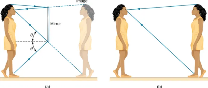
When you see yourself in a mirror, it appears that the image is actually behind the mirror (Figure 1.8). We see the light coming from a direction determined by the law of reflection. The angles are such that the image is exactly the same distance behind the mirror as you stand in front of the mirror. If the mirror is on the wall of a room, the images in it are all behind the mirror, which can make the room seem bigger. Although these mirror images make objects appear to be where they cannot be (like behind a solid wall), the images are not figments of your imagination. Mirror images can be photographed and videotaped by instruments and look just as they do with our eyes (which are optical instruments themselves). The precise manner in which images are formed by mirrors and lenses is discussed in an upcoming chapter onGeometric Optics and Image Formation.
Figure 1.8 (a) Your image in a mirror is behind the mirror. The two rays shown are those that strike the mirror at just the correct angles to be reflected into the eyes of the person. The image appears to be behind the mirror at the same distance away as (b) if you were looking at your twin directly, with no mirror.
Corner Reflectors (Retroreflectors)
A light ray that strikes an object consisting of two mutually perpendicular reflecting surfaces is reflected back exactly parallel to the direction from which it came (Figure 1.9). This is true whenever the reflecting surfaces are perpendicular, and it is independent of the angle of incidence. (For proof, see at the end of this section.) Such an object is called a corner reflector, since the light bounces from its inside corner. Corner reflectors are a subclass of retroreflectors, which all reflect rays back in the directions from which they came. Although the geometry of the proof is much more complex, corner reflectors can also be built with three mutually perpendicular reflecting surfaces and are useful in three-dimensional applications.
Figure 1.9 A light ray that strikes two mutually perpendicular reflecting surfaces is reflected back exactly parallel to the direction from which it came.
Many inexpensive reflector buttons on bicycles, cars, and warning signs have corner reflectors designed to return light in the direction from which it originated. Rather than simply reflecting light over a wide angle, retroreflection ensures high visibility if the observer and the light source are located together, such as a car’s driver and headlights. The Apollo astronauts placed a true corner reflector on the Moon (Figure 1.10). Laser signals from Earth can be bounced from that corner reflector to measure the gradually increasing distance to the Moon of a few centimeters per year.
Figure 1.10 (a) Astronauts placed a corner reflector on the Moon to measure its gradually increasing orbital distance. (b) The bright spots on these bicycle safety reflectors are reflections of the flash of the camera that took this picture on a dark night. (credit a: modification of work by NASA; credit b: modification of work by “Julo”/Wikimedia Commons)
Working on the same principle as these optical reflectors, corner reflectors are routinely used as radar reflectors (Figure 1.11) for radio-frequency applications. Under most circumstances, small boats made of fiberglass or wood do not strongly reflect radio waves emitted by radar systems. To make these boats visible to radar (to avoid collisions, for example), radar reflectors are attached to boats, usually in high places.
Figure 1.11 A radar reflector hoisted on a sailboat is a type of corner reflector. (credit: Tim Sheerman-Chase)
As a counterexample, if you are interested in building a stealth airplane, radar reflections should be minimized to evade detection. One of the design considerations would then be to avoid building 90° corners into the airframe.
1.3
|
Refraction
Learning Objectives
By the end of this section, you will be able to:
• Describe how rays change direction upon entering a medium • Apply the law of refraction in problem solving
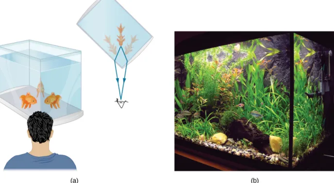
You may often notice some odd things when looking into a fish tank. For example, you may see the same fish appearing to be in two different places (Figure 1.12). This happens because light coming from the fish to you changes direction when it
leaves the tank, and in this case, it can travel two different paths to get to your eyes. The changing of a light ray’s direction (loosely called bending) when it passes through substances of different refractive indices is called refraction and is related to changes in the speed of light, v = c/n. Refraction is responsible for a tremendous range of optical phenomena, from the action of lenses to data transmission through optical fibers.
Figure 1.12 (a) Looking at the fish tank as shown, we can see the same fish in two different locations, because light changes directions when it passes from water to air. In this case, the light can reach the observer by two different paths, so the fish seems to be in two different places. This bending of light is called refraction and is responsible for many optical phenomena. (b) This image shows refraction of light from a fish near the top of a fish tank.
Figure 1.13shows how a ray of light changes direction when it passes from one medium to another. As before, the angles are measured relative to a perpendicular to the surface at the point where the light ray crosses it. (Some of the incident light is reflected from the surface, but for now we concentrate on the light that is transmitted.) The change in direction of the light ray depends on the relative values of the indices of refraction (The Propagation of Light) of the two media involved. In the situations shown, medium 2 has a greater index of refraction than medium 1. Note that as shown inFigure 1.13(a), the direction of the ray moves closer to the perpendicular when it progresses from a medium with a lower index of refraction to one with a higher index of refraction. Conversely, as shown inFigure 1.13(b), the direction of the ray moves away from the perpendicular when it progresses from a medium with a higher index of refraction to one with a lower index of refraction. The path is exactly reversible.
Figure 1.13 The change in direction of a light ray depends on how the index of refraction changes when it crosses from one medium to another. In the situations shown here, the index of refraction is greater in medium 2 than in medium 1. (a) A ray of light moves closer to the perpendicular when entering a medium with a higher index of refraction. (b) A ray of light moves away from the perpendicular when entering a medium with a lower index of refraction.
The amount that a light ray changes its direction depends both on the incident angle and the amount that the speed changes. For a ray at a given incident angle, a large change in speed causes a large change in direction and thus a large change in angle. The exact mathematical relationship is the law of refraction, or Snell’s law, after the Dutch mathematician Willebrord Snell (1591–1626), who discovered it in 1621. The law of refraction is stated in equation form as
(1.4)
n1 sin θ1= n2 sin θ2.
Here n1 and n2 are the indices of refraction for media 1 and 2, and θ1 and θ2 are the angles between the rays and the perpendicular in media 1 and 2. The incoming ray is called the incident ray, the outgoing ray is called the refracted ray, and the associated angles are the incident angle and the refracted angle, respectively.
Snell’s experiments showed that the law of refraction is obeyed and that a characteristic index of refraction n could be assigned to a given medium and its value measured. Snell was not aware that the speed of light varied in different media, a key fact used when we derive the law of refraction theoretically using Huygens’s principle inHuygens’s Principle.
Example 1.2
Determining the Index of Refraction
Find the index of refraction for medium 2 inFigure 1.13(a), assuming medium 1 is air and given that the incident angle is 30.0° and the angle of refraction is 22.0°.
Strategy
The index of refraction for air is taken to be 1 in most cases (and up to four significant figures, it is 1.000). Thus, n1= 1.00 here. From the given information, θ1= 30.0° and θ2= 22.0°. With this information, the only unknown in Snell’s law is n2, so we can use Snell’s law to find it.
Solution
From Snell’s law we have
n1 sin θ1 = n2 sin θ2
n2 = n1sin θ1 sin θ2.
1.2
Entering known values,
n2= 1.00sin 30.0°sin 22.0° = 0.5000.375 = 1.33.
Significance
This is the index of refraction for water, and Snell could have determined it by measuring the angles and performing this calculation. He would then have found 1.33 to be the appropriate index of refraction for water in all other situations, such as when a ray passes from water to glass. Today, we can verify that the index of refraction is related to the speed of light in a medium by measuring that speed directly.
Explorebending of light (https://openstaxcollege.org/l/21bendoflight)between two media with different indices of refraction. Use the “Intro” simulation and see how changing from air to water to glass changes the bending angle. Use the protractor tool to measure the angles and see if you can recreate the configuration in
Example 1.2. Also by measurement, confirm that the angle of reflection equals the angle of incidence.
Example 1.3
A Larger Change in Direction
Suppose that in a situation like that inExample 1.2, light goes from air to diamond and that the incident angle is 30.0°. Calculate the angle of refraction θ2 in the diamond.
Strategy
Again, the index of refraction for air is taken to be n1= 1.00, and we are given θ1= 30.0°. We can look up the index of refraction for diamond inTable 1.1, finding n2= 2.419. The only unknown in Snell’s law is θ2, which we wish to determine.
Solution
Solving Snell’s law for sin θ2 yields
sin θ2=nn1 2sin θ1.
Entering known values,
sin θ2= 1.002.419 sin 30.0° = (0.413)(0.500) = 0.207.
The angle is thus
θ2= sin−1(0.207) = 11.9°.
Significance
For the same 30.0° angle of incidence, the angle of refraction in diamond is significantly smaller than in water
(11.9° rather than 22.0°—seeExample 1.2). This means there is a larger change in direction in diamond. The cause of a large change in direction is a large change in the index of refraction (or speed). In general, the larger the change in speed, the greater the effect on the direction of the ray.
Check Your Understanding InTable 1.1, the solid with the next highest index of refraction after diamond is zircon. If the diamond inExample 1.3were replaced with a piece of zircon, what would be the new angle of refraction?
1.4
|
Total Internal Reflection
Learning Objectives
By the end of this section, you will be able to:
• Explain the phenomenon of total internal reflection • Describe the workings and uses of optical fibers • Analyze the reason for the sparkle of diamonds
A good-quality mirror may reflect more than 90% of the light that falls on it, absorbing the rest. But it would be useful to have a mirror that reflects all of the light that falls on it. Interestingly, we can produce total reflection using an aspect of refraction.
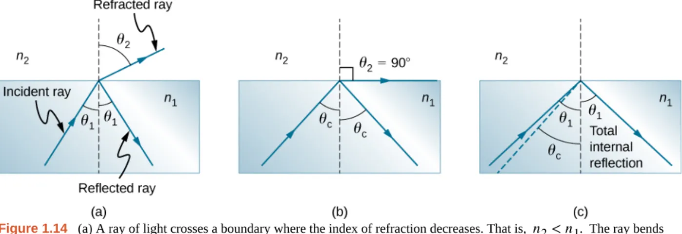
Consider what happens when a ray of light strikes the surface between two materials, as shown inFigure 1.14(a). Part of the light crosses the boundary and is refracted; the rest is reflected. If, as shown in the figure, the index of refraction for the second medium is less than for the first, the ray bends away from the perpendicular. (Since n1> n2, the angle of refraction is greater than the angle of incidence—that is, θ2> θ1.) Now imagine what happens as the incident angle increases. This causes θ2 to increase also. The largest the angle of refraction θ2 can be is 90°, as shown in part (b). The critical angle θc for a combination of materials is defined to be the incident angle θ1 that produces an angle of refraction of 90°. That is, θc is the incident angle for which θ2= 90°. If the incident angle θ1 is greater than the critical angle, as
shown inFigure 1.14(c), then all of the light is reflected back into medium 1, a condition called total internal reflection. (As the figure shows, the reflected rays obey the law of reflection so that the angle of reflection is equal to the angle of incidence in all three cases.)
Figure 1.14 (a) A ray of light crosses a boundary where the index of refraction decreases. That is, n2< n1. The ray bends away from the perpendicular. (b) The critical angle θc is the angle of incidence for which the angle of refraction is 90°. (c) Total internal reflection occurs when the incident angle is greater than the critical angle.
Snell’s law states the relationship between angles and indices of refraction. It is given by
n1sin θ1= n2sin θ2.
When the incident angle equals the critical angle ⎛
⎝θ1= θc⎞⎠, the angle of refraction is 90° ⎛⎝θ2= 90°⎞⎠. Noting that
sin 90° = 1, Snell’s law in this case becomes
n1sin θ1= n2.
1.3
(1.5)
θc= sin−1⎛⎝nn21⎞⎠ for n1> n2.
Total internal reflection occurs for any incident angle greater than the critical angle θc, and it can only occur when the second medium has an index of refraction less than the first. Note that this equation is written for a light ray that travels in medium 1 and reflects from medium 2, as shown inFigure 1.14.
Example 1.4
Determining a Critical Angle
What is the critical angle for light traveling in a polystyrene (a type of plastic) pipe surrounded by air? The index of refraction for polystyrene is 1.49.
Strategy
The index of refraction of air can be taken to be 1.00, as before. Thus, the condition that the second medium (air) has an index of refraction less than the first (plastic) is satisfied, and we can use the equation
θc= sin−1⎛⎝nn2 1⎞⎠
to find the critical angle θc, where n2= 1.00 and n1= 1.49.
Solution
Substituting the identified values gives
θc= sin−1⎛⎝1.001.49⎞⎠= sin−1(0.671) = 42.2°.
Significance
This result means that any ray of light inside the plastic that strikes the surface at an angle greater than 42.2° is totally reflected. This makes the inside surface of the clear plastic a perfect mirror for such rays, without any need for the silvering used on common mirrors. Different combinations of materials have different critical angles, but any combination with n1> n2 can produce total internal reflection. The same calculation as made here shows that the critical angle for a ray going from water to air is 48.6°, whereas that from diamond to air is 24.4°, and that from flint glass to crown glass is 66.3°.
Check Your Understanding At the surface between air and water, light rays can go from air to water and from water to air. For which ray is there no possibility of total internal reflection?
In the photo that opens this chapter, the image of a swimmer underwater is captured by a camera that is also underwater. The swimmer in the upper half of the photograph, apparently facing upward, is, in fact, a reflected image of the swimmer below. The circular ripple near the photograph’s center is actually on the water surface. The undisturbed water surrounding it makes a good reflecting surface when viewed from below, thanks to total internal reflection. However, at the very top edge of this photograph, rays from below strike the surface with incident angles less than the critical angle, allowing the camera to capture a view of activities on the pool deck above water.
Fiber Optics: Endoscopes to Telephones
Fiber optics is one application of total internal reflection that is in wide use. In communications, it is used to transmit telephone, internet, and cable TV signals. Fiber optics employs the transmission of light down fibers of plastic or glass. Because the fibers are thin, light entering one is likely to strike the inside surface at an angle greater than the critical angle and, thus, be totally reflected (Figure 1.15). The index of refraction outside the fiber must be smaller than inside. In fact,
Figure 1.15 Light entering a thin optic fiber may strike the inside surface at large or grazing angles and is completely reflected if these angles exceed the critical angle. Such rays continue down the fiber, even following it around corners, since the angles of reflection and incidence remain large.
Bundles of fibers can be used to transmit an image without a lens, as illustrated inFigure 1.16. The output of a device called an endoscope is shown inFigure 1.16(b). Endoscopes are used to explore the interior of the body through its natural orifices or minor incisions. Light is transmitted down one fiber bundle to illuminate internal parts, and the reflected light is transmitted back out through another bundle to be observed.
Figure 1.16 (a) An image “A” is transmitted by a bundle of optical fibers. (b) An endoscope is used to probe the body, both transmitting light to the interior and returning an image such as the one shown of a human epiglottis (a structure at the base of the tongue). (credit b: modification of work by “Med_Chaos”/Wikimedia Commons)
Fiber optics has revolutionized surgical techniques and observations within the body, with a host of medical diagnostic and therapeutic uses. Surgery can be performed, such as arthroscopic surgery on a knee or shoulder joint, employing cutting tools attached to and observed with the endoscope. Samples can also be obtained, such as by lassoing an intestinal polyp for external examination. The flexibility of the fiber optic bundle allows doctors to navigate it around small and difficult-to-reach regions in the body, such as the intestines, the heart, blood vessels, and joints. Transmission of an intense laser beam to burn away obstructing plaques in major arteries, as well as delivering light to activate chemotherapy drugs, are becoming commonplace. Optical fibers have in fact enabled microsurgery and remote surgery where the incisions are small and the
surgeon’s fingers do not need to touch the diseased tissue.
Optical fibers in bundles are surrounded by a cladding material that has a lower index of refraction than the core (Figure 1.17). The cladding prevents light from being transmitted between fibers in a bundle. Without cladding, light could pass between fibers in contact, since their indices of refraction are identical. Since no light gets into the cladding (there is total internal reflection back into the core), none can be transmitted between clad fibers that are in contact with one another. Instead, the light is propagated along the length of the fiber, minimizing the loss of signal and ensuring that a quality image is formed at the other end. The cladding and an additional protective layer make optical fibers durable as well as flexible.
Figure 1.17 Fibers in bundles are clad by a material that has a lower index of refraction than the core to ensure total internal reflection, even when fibers are in contact with one another.
Special tiny lenses that can be attached to the ends of bundles of fibers have been designed and fabricated. Light emerging from a fiber bundle can be focused through such a lens, imaging a tiny spot. In some cases, the spot can be scanned, allowing quality imaging of a region inside the body. Special minute optical filters inserted at the end of the fiber bundle have the capacity to image the interior of organs located tens of microns below the surface without cutting the surface—an area known as nonintrusive diagnostics. This is particularly useful for determining the extent of cancers in the stomach and bowel.
In another type of application, optical fibers are commonly used to carry signals for telephone conversations and internet communications. Extensive optical fiber cables have been placed on the ocean floor and underground to enable optical communications. Optical fiber communication systems offer several advantages over electrical (copper)-based systems, particularly for long distances. The fibers can be made so transparent that light can travel many kilometers before it becomes dim enough to require amplification—much superior to copper conductors. This property of optical fibers is called low loss. Lasers emit light with characteristics that allow far more conversations in one fiber than are possible with electric signals on a single conductor. This property of optical fibers is called high bandwidth. Optical signals in one fiber do not produce undesirable effects in other adjacent fibers. This property of optical fibers is called reduced crosstalk. We shall explore the unique characteristics of laser radiation in a later chapter.
Corner Reflectors and Diamonds
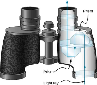
Corner reflectors (The Law of Reflection) are perfectly efficient when the conditions for total internal reflection are satisfied. With common materials, it is easy to obtain a critical angle that is less than 45°. One use of these perfect mirrors is in binoculars, as shown inFigure 1.18. Another use is in periscopes found in submarines.
Figure 1.18 These binoculars employ corner reflectors (prisms) with total internal reflection to get light to the observer’s eyes.
Total internal reflection, coupled with a large index of refraction, explains why diamonds sparkle more than other materials. The critical angle for a diamond-to-air surface is only 24.4°, so when light enters a diamond, it has trouble getting back out (Figure 1.19). Although light freely enters the diamond, it can exit only if it makes an angle less than 24.4°. Facets on diamonds are specifically intended to make this unlikely. Good diamonds are very clear, so that the light makes many internal reflections and is concentrated before exiting—hence the bright sparkle. (Zircon is a natural gemstone that has an exceptionally large index of refraction, but it is not as large as diamond, so it is not as highly prized. Cubic zirconia is manufactured and has an even higher index of refraction (≈2.17), but it is still less than that of diamond.) The colors you see emerging from a clear diamond are not due to the diamond’s color, which is usually nearly colorless. The colors result from dispersion, which we discuss inDispersion. Colored diamonds get their color from structural defects of the crystal lattice and the inclusion of minute quantities of graphite and other materials. The Argyle Mine in Western Australia produces around 90% of the world’s pink, red, champagne, and cognac diamonds, whereas around 50% of the world’s clear diamonds come from central and southern Africa.
Figure 1.19 Light cannot easily escape a diamond, because its critical angle with air is so small. Most reflections are total, and the facets are placed so that light can exit only in particular ways—thus concentrating the light and making the diamond sparkle brightly.
Explorerefraction and reflection of light (https://openstaxcollege.org/l/21bendoflight)between two media with different indices of refraction. Try to make the refracted ray disappear with total internal reflection. Use the protractor tool to measure the critical angle and compare with the prediction fromEquation 1.5.
1.5
|
Dispersion
Learning Objectives
By the end of this section, you will be able to: • Explain the cause of dispersion in a prism
• Describe the effects of dispersion in producing rainbows • Summarize the advantages and disadvantages of dispersion
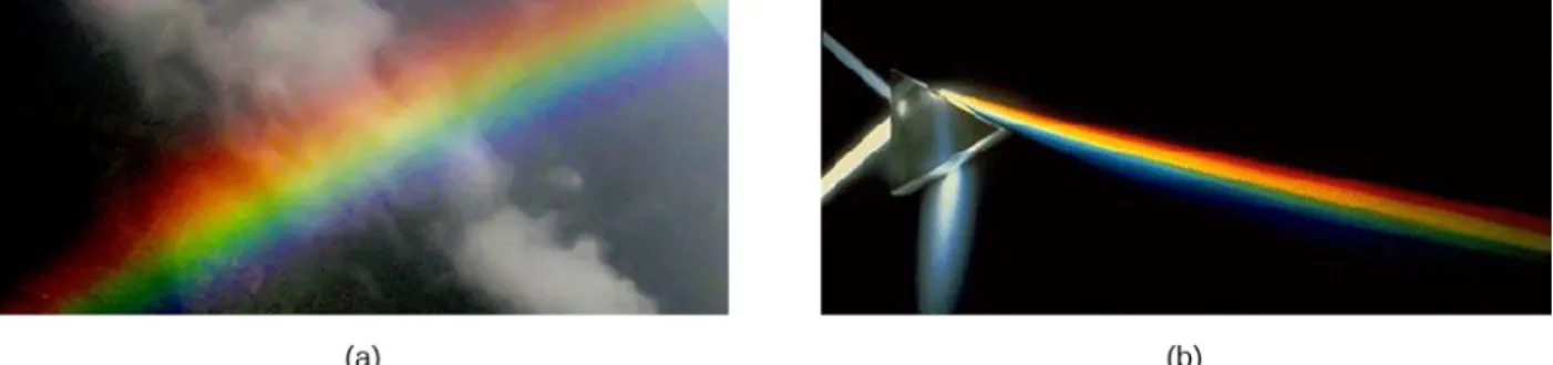
Everyone enjoys the spectacle of a rainbow glimmering against a dark stormy sky. How does sunlight falling on clear drops of rain get broken into the rainbow of colors we see? The same process causes white light to be broken into colors by a clear glass prism or a diamond (Figure 1.20).
Figure 1.20 The colors of the rainbow (a) and those produced by a prism (b) are identical. (credit a: modification of work by “Alfredo55”/Wikimedia Commons; credit b: modification of work by NASA)
We see about six colors in a rainbow—red, orange, yellow, green, blue, and violet; sometimes indigo is listed, too. These colors are associated with different wavelengths of light, as shown inFigure 1.21. When our eye receives pure-wavelength light, we tend to see only one of the six colors, depending on wavelength. The thousands of other hues we can sense in other situations are our eye’s response to various mixtures of wavelengths. White light, in particular, is a fairly uniform mixture of all visible wavelengths. Sunlight, considered to be white, actually appears to be a bit yellow, because of its mixture of wavelengths, but it does contain all visible wavelengths. The sequence of colors in rainbows is the same sequence as the colors shown in the figure. This implies that white light is spread out in a rainbow according to wavelength. Dispersion is defined as the spreading of white light into its full spectrum of wavelengths. More technically, dispersion occurs whenever the propagation of light depends on wavelength.
Figure 1.21 Even though rainbows are associated with six colors, the rainbow is a continuous distribution of colors according to wavelengths.
interaction with the tube. Dispersion, in fact, can reveal a great deal about what the wave has encountered that disperses its wavelengths. The dispersion of electromagnetic radiation from outer space, for example, has revealed much about what exists between the stars—the so-called interstellar medium.
Nick Moore’svideo (https://openstaxcollege.org/l/21nickmoorevid)discusses dispersion of a pulse as he taps a long spring. Follow his explanation as Moore replays the high-speed footage showing high frequency waves outrunning the lower frequency waves.
Refraction is responsible for dispersion in rainbows and many other situations. The angle of refraction depends on the index of refraction, as we know from Snell’s law. We know that the index of refraction n depends on the medium. But for a given medium, n also depends on wavelength (Table 1.2). Note that for a given medium, n increases as wavelength decreases and is greatest for violet light. Thus, violet light is bent more than red light, as shown for a prism inFigure 1.22(b). White light is dispersed into the same sequence of wavelengths as seen inFigure 1.20andFigure 1.21.
Medium Red (660 nm) Orange (610 nm) Yellow (580 nm) Green (550 nm) Blue (470 nm) Violet (410 nm) Water 1.331 1.332 1.333 1.335 1.338 1.342 Diamond 2.410 2.415 2.417 2.426 2.444 2.458 Glass, crown 1.512 1.514 1.518 1.519 1.524 1.530 Glass, flint 1.662 1.665 1.667 1.674 1.684 1.698 Polystyrene 1.488 1.490 1.492 1.493 1.499 1.506 Quartz, fused 1.455 1.456 1.458 1.459 1.462 1.468
Table 1.2 Index of Refraction n in Selected Media at Various Wavelengths
Figure 1.22 (a) A pure wavelength of light falls onto a prism and is refracted at both surfaces. (b) White light is dispersed by the prism (shown exaggerated). Since the index of refraction varies with wavelength, the angles of refraction vary with wavelength. A sequence of red to violet is produced, because the index of refraction increases steadily with decreasing wavelength.
Example 1.5
Dispersion of White Light by Flint Glass
A beam of white light goes from air into flint glass at an incidence angle of 43.2°. What is the angle between the red (660 nm) and violet (410 nm) parts of the refracted light?
1.4
Strategy
Values for the indices of refraction for flint glass at various wavelengths are listed inTable 1.2. Use these values for calculate the angle of refraction for each color and then take the difference to find the dispersion angle.
Solution
Applying the law of refraction for the red part of the beam
nairsin θair= nred sin θred,
we can solve for the angle of refraction as
θred= sin−1
⎛
⎝
nairsin θairnred
⎞
⎠
= sin−1⎡⎣(1.000) sin 43.2°(1.662) ⎤⎦ = 27.0°.Similarly, the angle of incidence for the violet part of the beam is
θviolet= sin−1
⎛
⎝
nairsin θairnviolet
⎞
⎠
= sin−1⎡⎣(1.000) sin 43.2°(1.698) ⎤⎦ = 26.4°.The difference between these two angles is
θred− θviolet= 27.0° − 26.4° = 0.6°.
Significance
Although 0.6° may seem like a negligibly small angle, if this beam is allowed to propagate a long enough distance, the dispersion of colors becomes quite noticeable.
Check Your Understanding In the preceding example, how much distance inside the block of flint glass would the red and the violet rays have to progress before they are separated by 1.0 mm?
Rainbows are produced by a combination of refraction and reflection. You may have noticed that you see a rainbow only when you look away from the Sun. Light enters a drop of water and is reflected from the back of the drop (Figure 1.23). The light is refracted both as it enters and as it leaves the drop. Since the index of refraction of water varies with wavelength, the light is dispersed, and a rainbow is observed (Figure 1.24(a)). (No dispersion occurs at the back surface, because the