Protein Amyloid Fibrils as Template for the Synthesis of Silica
Nanofibers, and Their Use to Prepare Superhydrophobic,
Lotus-Like Surfaces
Simonetta Rima and Marco Lattuada*
Dr. S. Rima
Adolphe Merkle Institute University of Fribourg
Chemin des Verdiers 4, CH-1700 Fribourg, Switzerland Prof. M. Lattuada
Department of Chemistry University of Fribourg
Chemin du Musée 9, CH-1700 Fribourg, Switzerland E-mail: marco.lattuada@unifr.ch
1. Introduction
Multifunctional silica nanotubes and nanofibers have been the focus of a large amount of research over the last decades, since they have the potential to provide important contributions to several fields, such as biomedicine, where they have been investigated as drug delivery vehicles, for gene delivery, in imaging and screening, in targeting and cell sorting, in molecular separations and bio-sensing, bioseparation, and biocatalysis.[1] Numerous challenges have still to be overcome to provide well-defined silica nanotubes. It is especially crucial to provide a large-scale synthesis of high-quality silica nanotubes with a facile and reproducible process.
In this work, amyloid fibrils are used as a template for the preparation of long silica fibers, with a variety of aspect ratios and surface roughness. Starting with β-lactoglobulin fibrils with typical diameters of about 20 nm and a length of several micrometers, two different strategies are followed to grow silica: either in water at acidic pH values, or in ethanol–water mixtures under Stöber conditions and an excellent control of both the thickness and the rough-ness of the silica layer has been achieved. Silica nanofibers with a thickrough-ness ranging from a few nanometers to hundreds of nanometers are prepared. As an application, the rough silica nanotubes are used to create superhydro-phobic surfaces by mimicking the structure of the lotus leaf. The papillary structure of the lotus leaf is replicated by depositing 10 μm colloidal parti-cles in either a single colloidal crystal, or in a binary colloidal crystal made with smaller sub-micrometer particles. Then, silica nanofibers are deposited on the binary colloidal crystal surfaces through a layer-by-layer deposition procedure to replicate the nanoscale roughness provided by wax nanotubes. Upon hydrophobization of the silica nanotubes, the final surfaces are highly superhydrophobic, with a water contact angle of 165.5°.
Silica nanotubes were first prepared by Nakamura and Matsui[2] and since then several studies have been published focusing on preparation strategies, on the characterization of their properties and on the development of further function-alization procedures. From that point on, different methods, most of them starting from a template, have been used for the synthesis of silica nanotubes. One of the most important aspects of template-directed synthesis is the selection of a template that ensures the formation of the desired nanostructure and can be easily removed by post-treatment (e.g., extrac-tion, chemical reacextrac-tion, or calcination). The coating of the templates with silica can be performed through the use of sol-gel processes,[3] hydrothermal synthesis,[4] and microemulsion templating.[5] Tem-plates can be classified into three main categories: organic templates, inorganic templates, and biomolecular templates. The first group of templates are inorganic templates, which have been divided in two main subgroups: porous inorganic membranes and inorganic nanomaterials. The first exam-ples of inorganic membranes template have been intro-duced by Martin,[6] who prepared nanofibers starting from porous alumina membranes with a sol-gel coating technique. Nanorods, nanowires, or hollow nanotubes of different mate-rials have been obtained by dissolving the alumina template. More recently, the same approach has been used by He et al., using inorganic anodic aluminum oxide (AAO), producing silica nanotubes with well-defined cylindrical pores by a mul-tistep anodization template synthesis.[7] Examples of inorganic nanomaterials, on the other hand, are multi or single-walled carbon nanotubes,[8] hyperbranched PbSe nanowires,[9] silicon nanowires,[10] ZnO nanowires,[11] Gd(OH)
3 nanorods,[12] or gold nanorods.[13] Only a small spectrum of materials is suitable to act as templates, although most inorganic templates are ther-mally and chemically stable with respect to the specific reaction conditions. Their versatility is however limited.
The second group of templates, that is, organic templates, have received an increased interest in the last decades in com-parison with their inorganic counterparts. They are character-ized by a broad structural variety, are easily removed, have good solubility and dispersibility in solution. A variety of organic templates have been successfully used for the sol-gel synthesis
http://doc.rero.ch
of hollow silica nanotubes, such as surfactants,[14] acids,[15] block copolymers,[16] and gelling systems.[17] An important class of compounds that has been used as templates is chiral gelators, which allow the preparation of chiral or helical silica nanotubes. Wan et al.[18] showed the preparation of helical silica nanotubes using different chiral cationic gelators, reporting the formation of long-range order nanostructured silica, in which the diam-eters of the nanotubes retain the length of gelators. Twisted silica nanoribbons were also obtained by Okazaki et al.[19] via acidification of tetraethoxysilane (TEOS) solution in the pres-ence of chiral acid (tartaric acid), using organic self-assembly as a template. Organic templates offer a broad range of dif-ferent and tunable structure, but they often require synthetic chemistry where multiple-step reactions and the use of organic solvents or toxic substances are involved.
In the last decade several biomolecules that display mor-phologically complex architectures have also attracted interest as biotemplates. Since nature is a great source of inspiration for the formation of well-defined structured silica, it seems straightforward to use biomolecules to fabricate silica materials. A large variety of biomolecules have been used as a template, such as tobacco mosaic virus (TMV),[20] DNA,[21] lipids,[22] or peptides.[23,24] The tobacco mosaic virus (TMV) is a remarkable stable virus, made of several identical protein subunits covered with positively charged amino acid residues, which make it par-ticularly suitable for silica anions templating.[20] On the other end, DNA itself is an anionic polymer, which requires to be transformed in cationic form.[21]
The use of peptides as templates has been deemed particu-larly promising. Meegan et al. first reported the sol-gel hydrol-ysis and condensation of TEOS using self-assembled β-sheet peptide fibril templates.[24] The template was removed by extrac-tion, producing hollow silica nanotubes with an outer diameter of 20 nm and an inner diameter of about 3.5 nm. The central pore has been showed to reflect the dimension of the peptide fibril and is expected to be chiral. The diameter and length of silica nanotubes are primarily determined by the self-assembled fibril template. Tuning the synthesis conditions, such as pH values, peptides chemistry, and catalysts, led to the formation of silica nanotubes with different morphologies. More recently, Wang et al. reported an effective approach for preparing 1D silica nanostructures by using anionic–organic matrices made of self-assembled short peptides. By using aminopropyl-trieth-oxysilane (APTES) and TEOS as silica precursors, silica nano-tubes with controlled sizes were fabricated. The size of such silica nanotubes could be tuned by changing the interactions among the peptide templates and the silica precursor.[23a,25]
In the present work, we introduce a new class of templates, that is, amyloid fibrils obtained from proteins. Amyloid protein fibrils in the last years have gained an increased interest in nanotechnology, and their use has been pioneered by the Mez-zenga group, who already adopted them for the preparation of many advanced materials, such as bone biomimetic compos-ites, shape memory and enzyme-sensing properties, magnetic responsive gels, water purification, and many more.[26] When choosing the right protein, such as β-lactoglobulin, amyloid fibrils can be easily prepared in large quantities and are char-acterized by a positive surface charge at low pH values, thus offering a large and prone surface for the condensation and
hydrolysis of silica precursors, such as TEOS or tetramethy-lorthosilicate (TMOS). In a recent work, the Serpel group also used amyloid fibrils as templates for the growth of silica nanotubes, but these fibrils were prepared from short pep-tides with a defined sequence, which had already been used as templates for silica growth.[25] The first objective of this work is the investigation of the hydrolysis and condensation of TMOS under aqueous acidic environments as well as the hydrolysis and condensation of TEOS under Stöber condition using β-lactoglobulin amyloid fibrils as templates. The forma-tion of silica nanotubes or nanofibers with tunable thickness and roughness has been investigated, and their further surface hydrophobization and subsequent use to prepare superhydro-phobic surfaces is also demonstrated.
Exploiting the strong resemblance of some of the rough silica nanotubes prepared and the wax nanotubules found on the surface of a lotus leaf, we decided then to mimic its structure to prepare more effective bioinspired superhydro-phobic surfaces. The lotus leaf surface presents a unique hierarchical structure, with roughness at two different length scales.[27] On the microscale, there are papillae, with a typical size of 10–20 μm and a surface density of about 3400 mm−2, which are the basis for the reduced contact area between the leaf surface and water droplets. On top of the papillae there is a dense layer of very small epicuticular wax tubules, unique in chemical composition (C29-diols, with a melting point of 90°–95°).[28] The contact angle of water droplets on the surface of lotus leaves exceeds 150°, which is typical of superhydro-phobic surfaces, and the roll-off angle is lower than 10°. These features give rise to the so-called self-cleaning lotus effect. It is well established that surface roughness strongly affects hydrophobicity.[29] It is because of the large papillae been sufficiently densely packed on the surface to prevent water droplet to wet the space among the papillae that the superhydrophobic effect is reached.[29b]
An ample research work on the preparation and characteri-zation of bioinspired superhydrophobic surfaces is available in the literature.[29b,30] To prepare surfaces with hierarchical structure, we combined particles lithography to prepare either single binary colloidal crystal structure using monodisperse polystyrene (PS) colloids to reproduce large-scale papillary structure of the lotus leaf. To create the nanoscale epicuticular roughness provided by the wax nanotubes on the lotus leaf structure, a layer-by-layer (LbL) deposition of silica nanofibers has been carried out on the colloidal crystals, and then hydro-phobically modified to attach long alkyl chains to their surface. The structure of the surfaces has been characterized by scan-ning electron microscopy (SEM), and the wetting behavior of the surfaces obtained throughout the various stages has been quantified by water contact angle (WCA) measurements.
2. Results and Discussion
The work has been divided in two parts. In the first part of this work, we have developed a simple strategy for the prepa-ration of silica nanotubes using amyloid fibrils as templates. In the second part of the work, some of the silica nanotubes prepared in the first part of the work have been used to create
superhydrophobic surfaces, with a structure mimicking the structure of the lotus leaf. Figure 1 shows a schematic of the entire process.
2.1. Preparation of Silica Nanotubes
2.1.1. TMOS Hydrolysis under Acid Conditions
Two sol-gel approaches have been utilized for the preparation of silica nanotubes: hydrolysis of TMOS in acidic aqueous solu-tions, and hydrolysis of TEOS in Stöber process in ethanol (EtOH)–water mixtures under basic conditions. The former approach has been used because amyloid fibrils are prepared under acidic conditions, and at low pH values they possess a positive charge, as confirmed by ζ-potential measurements, reported in Figure S2 (Supporting Information), where the ζ-potential of naked β-lactoglobulin fibrils has been measured as a function of pH. One can observe that the amyloid fibrils maintain a positive charge below pH 4.5. It is well known that the combination of negatively charged silicate anions and positively charged templates can be successfully used for tem-plating under acidic aqueous conditions.[23b] Therefore, we have begun by considering hydrolysis–condensation of TMOS with positively charged protein fibrils. The formation of a silica layer on the surface of amyloid fibrils has been performed under acidic conditions (pH 3.0), using a concentration of fibrils of 1 g L−1, and different amounts of TMOS.
The pH and cosolvent conditions are well known to affect the morphology of silica nucleation both in the presence and in the absence of a template. After 12 h incubation of amyloid fibrils with TMOS at pH 3.0, the system was completely gelled, indicating a homogenous condensation of TMOS in water in the form of small spherical particles, in addition to a coating of amyloid fibrils. This was confirmed by looking at the behavior of TMOS in water at pH 3.0 without fibrils, in which case a gel
was formed after 24 h, while in the presence of the fibrils we observed the formation of a gel already after 12 h. We analyzed the samples TMOS/fibrils incubated for 12 h, before centrifu-gation, via SEM imaging (reported in Figure S3, Supporting Information) and we observed the formation of a large amount of small spherical particles, making it difficult to recognize the coated fibrils.
We therefore decided to stop the reaction after only 4 h of incubation time, before the gel formation, to minimize sec-ondary nucleation. We separated the fibrils from the excess of TMOS by means of five centrifugation–redispersion cycles. The coated fibrils have then been analyzed via atomic force microscopy (AFM) and transmission electron microscopy (TEM). The operating conditions for this study are reported in
Table 1. Figure 2 shows the AFM pictures of TEOS/fibrils
sam-ples, incubated for 4 h with four different amounts of TEOS: Figure 2a, 3 μL, Figure 2b, 5 μL, Figure 2c, 100 μL, and Figure 2d, 300 μL. The cross-sectional diameters of the coated fibrils were measured in a semiautomatic manner using the image processing toolbox of Fiji (part of ImageJ software) and the average values were calculated from the combination of ten sets of measurements. By increasing the content of TMOS we observed an increase in the thickness of the final fibrils, in the range of 3–10 nm in thickness, in comparison with the original
Figure 1. Schematic of the process used to obtain silica fibers, and of the method used to prepare superhydrophobic surfaces using silica fibers,
mimicking the structure of lotus leaf.
Table 1. Details of the recipe and thickness of the fibrils coated with a
silica layer, obtained using TMOS as a silica precursor, and performing the hydrolysis–condensation under acidic conditions.
Sample name
[mL] of fibril solution
(concentration: 10 g L−1)H2O [mL] pH value TMOS [μL] Thickness after coating [nm]
SFw-1 1 9 3.0 30 25 ± 2
SFw-2 1 9 3.0 50 27 ± 2
SFw-3 1 9 3.0 100 31 ± 3
SFw-4 1 9 3.0 300 34 ± 3
fibrils. With this approach, increasing the silica precursor con-centration does not lead to a proportional increase in thickness of the silica layer on the amyloid fibrils. In all cases, only layers with a thickness of a few nanometers have been observed, indi-cating that the hydrolysis and condensation kinetics of TMOS under the investigated conditions is rather slow.
The template, that is, the amyloid fibrils, is made by single proteins that build the long filaments, which subsequently self-assemble side by side to form ribbon-like twisted fibers. From the AFM picture, reported in Figure 2, it is worth noticing that it is still possible to resolve the twisting of the fibrils coated with silica, especially for the case SFw-1 reported in Figure 2a. TEM analysis revealed fibers slightly coated with a layer of silica, but the estimation of the silica layer thickness from the measurement of inner and outer diameters could not be per-formed. To remove the fibril templates and obtain pure silica nanotubes, the coated fibrils of sample SFw-4 were calcined in an oven (Nabertherm P330) at 550 °C for 12 h, to ensure the full removal of the organic part (i.e., the β-lactoglobulin fibrils). This was verified by thermogravimetric analysis of naked amyloid fibrils, shown in Figure S3 (Supporting Infor-mation), which clearly indicates that at a temperature of 550 °C
the organic part of the fibril is reduced to 20%. The so-obtained silica nanofibers were transferred to water, redispersed under sonication (2 h, 0.5 s cycle, 60% amplitude) and analyzed via TEM. The images of the silica tubes are reported in Figure 3 at two different magnifications. This experiment confirmed the formation of the silica layer on the amyloid fibrils, in agree-ment with the AFM information. We can conclude that this procedure leads to the formation of very thin and uniform silica coating on the amyloid fibrils, leaving their ribbon-like struc-ture unaltered. Upon calcination, silica nanotubes can thus be prepared.
2.1.2. TEOS Hydrolysis under Stöber Conditions
The second approach used to coat the fibrils with a silica layer is based on sol-gel process in ethanol–water mixtures. A sche-matic of the reactions is reported in Figure 1. A silica layer has been grown on the amyloid fibrils following a Stöber method, which consists of an ammonia-catalyzed hydrolysis and con-densation of silica precursor, TEOS. Several conditions have been analyzed. Under the first conditions probed, the original
Figure 2. AFM images of amyloid fibrils coated with silica layer. Silica precursor: TMOS, hydrolysis–condensation performed in acidic environment.
Operating conditions reported in Table 1: a) 30 μL-TMOS SFw-1; b) 50 μL-TMOS SFw-2; c) 100 μL-TMOS SFw-3; d) 300 μL-TMOS SFw-4. Images size: 3 μm × 3 μm.
fibrils solution at the concentration of 10 g L−1 in water has been diluted ten times in EtOH with various amounts of TEOS/ ammonia. Different concentrations of silica precursor have been examined. A set of SEM images of the obtained silica-coated fibrils is shown in Figure 4. By increasing the TEOS/ fibril ratio an increase in silica layer thickness is obtained. As shown in Figure 4, for 500 μL TEOS (Figure 4a) the final diameter of the fibrils is around 210 ± 30 nm, for 100 μL TEOS (Figure 4b), 135 ± 40 nm, for 50 μL TEOS (Figure 4c), 93 ± 25 nm, and for 30 μL TEOS (Figure 4d) and 60 ± 15 nm. The hydrolysis and condensation of TEOS occurred consider-ably faster than with TMOS, and already in the first hour of reaction we observed precipitation and change in turbidity of the solution. In no case gelation has been observed, and the formation of clearly templated silica structures was observed.
At lower amounts of TEOS some of the nanofibers seem to aggregate, which may be either due to their polymeriza-tion together during the synthesis, or simply due to the drying process during the sample preparation for electron microscopy analysis. The diameter of the original protein fibrils is in the range of 20 nm (as it can be seen in the AFM picture in Figure S1, Supporting Information), while the coated fibrils have a thick-ness that ranges from around 60 to 250 nm. For low concen-trations of TEOS the silica coating is quite rough, and some secondary nucleation occurs. As the concentration of TEOS increases, the surface of the nanofibers becomes considerably smoother. Almost in every samples, the formation of spherical nanoparticles was observed, which can however be separated from the coated fibrils by centrifugation (15 min at 30 000G, Beckmann Coulter Centrifuge Avanti J-26 XP). The formation of spherical particles can be either due to a homogeneous secondary nucleation process or to the growth of silica layer around small protein-oligomers or very short fibrils.
To minimize the unwanted secondary nucleation and achieve a better control and uniformity of the silica shell, a different procedure has been investigated. The TEOS has been fed to the system in a semibatch mode, by means of a syringe pump, at a flow rate of 0.5 mL h−1. At the same time, the effect of several parameters has been investigated: the TEOS/ammonia amount at fixed equal volume ratio, the concentration of fibrils in the system (reduced ten times), and the effect of TEOS/ammonia ratio, by decreasing the ammonia content with respect to the TEOS. The fibrils prepared with this different approach
have been analyzed using SEM as reported in Figure 4e–g. Additional images of the silica nanotubes can be found in Figures S4–S6 (Supporting Information). By using a semibatch feeding the formed fibrils became longer as compared to the batch reaction case. The coated fibrils are clearly separated whenever higher amount of TEOS has been used (SFp-5 of Table 2). This can be seen in Figure 4e. These fibrils are
charac-terized by a remarkable homogeneous and smooth layer when compared to the other operating conditions (as can also be observed in Figure S6, Supporting Information). On the other hand, for lower concentration of TEOS the surface of the silica layer is rougher, as can be seen in Figure 4f,g and in Figure S6 (Supporting Information). However, the formation of some spherical nanoparticles has still been observed. By decreasing the amount of ammonia in the system the final layer of silica became less smooth, and secondary nucleation has been clearly reduced. SEM images for the samples with varied amount of ammonia have been reported in Figure 4h,i,l, which refer to the conditions SFp-11, SFp-9, and SFp-10, respectively. The results of these experiments clearly show that by changing the amount of ammonia or the overall amount of TEOS it is possible to tune the roughness of the fibrils coated surface as well as their final thickness. In Figure S5 (Supporting Information), an overview of SEM pictures at high magnifications for the fibril prepared at different amount of TEOS or ammonia/TEOS ratio is reported. It shows the tunability of roughness of the formed silica fibrils by changing the TEOS/ammonia ratio or the overall amount of TEOS. Very rough surface is observed for the sample SFp-6, representative of low amount of TEOS (Figure S5a, Supporting Information). The condition of high TEOS amount and lower TEOS/ammonia ratio represents the intermediate condition and is shown for sample SFp-11 in Figure S5b (Supporting Information). Very smooth fibrils were instead observed in the sample SFp-5 for the higher amount of TEOS and TEOS/ ammonia ratio, as reported in Figure S5c (Supporting Infor-mation). The results suggest the following mechanism for the growth of silica on the surface of the amyloid fibrils. First, the TEOS first nucleates in the form of spherical particles on the fibrils surface as can be seen in Figure S5a (Supporting Information). When the amount of TEOS is sufficiently high, silica keeps on growing on the surface creating a smooth layer, which cannot be achieved for low amount of TEOS or for low amount of catalyst. We also investigated the effect of the overall
Figure 3. TEM images of amyloid fibrils coated with silica layer after calcination at 550 °C. The calcined sample corresponds to sample SFw-4, reported in Table 1.
concentration of amyloid fibrils in the system, by performing the coating reaction for a fibril concentration ten times smaller. As it can be seen in Figure 4m, reducing the concentration of fibrils as well as the one of all the reagents leads to a more entangled fibrillar network, suggesting that all the fibrils poly-merize together during the hydrolysis and condensation of TEOS. This can be attributed to the drastic slowing down of the process, caused by the low amount of catalyst, that allows the fibrils to interconnect to each other during the silica growth.
2.2. Use of Silica Nanofibers for the Preparation of Superhydrophobic Surfaces
2.2.1. Simple Surfaces with Nanoscale Roughness Created by Silica Nanofibers
By looking at Figure S7 (Supporting Information), showing a direct comparison of an SEM image of wax nanotubes found on the surface of lotus leaves and that of silica nanotubes SFp-5, one
Figure 4. SEM images of silica-coated fibrils for fibril/TEOS for all samples reported in Table 2: a) SF-4 (500 μL TEOS, 500 μL ammonia, batch process), b) SF-3 (100 μL TEOS, 100 μL ammonia, batch process), c) SF-2 (50 μL TEOS, 50 μL ammonia, batch process), d) SF-1 (30 μL TEOS, 30 μL ammonia, batch process), e) SFp-5 (500 μL TEOS, 500 μL ammonia, semibatch process), f) SFp-6 (100 μL TEOS, 100 μL ammonia, semibatch process), g) SFp-7
(30 μL TEOS, 30 μL ammonia, semibatch process), h) SFp-11 (500 μL TEOS, 200 μL ammonia, semibatch process), i) SFp-9 (500 μL TEOS, 100 μL
ammonia, semibatch process), l) SFp-10 (500 μL TEOS, 50 μL ammonia, semibatch process), m) SFp-8 (diluted system, concentration of amyloid fibrils
0.1 g L−1, 50 μL TEOS, 50 μL ammonia), and n) summary of all relative diameters for the different samples reported in Table 2.
cannot miss the strong visual similarity between the two types of nanostructures. This motivated us to use some of the silica nanotubes for the preparation of superhydrophobic surfaces. To verify our hypothesis, we performed some preliminary tests. Decyl trimethoxysilane (DTS) has been grafted to the surface of silica fibrils under Stöber conditions, and the choice has fallen on fibrils SFp-5 and SFp-10 of Table 2, reported in Figure 4e,l, respectively, since they are representative of two main types of fibrils, the first ones characterized by smooth surface and the
second ones by a very rough surface. The two kinds of fibrils have been prepared with same amount of silica precursor but different amounts of ammonia. The first batch of fibrils are particularly smooth, and covered by a uniform layer of silica, while those obtained by decreasing the amount of ammonia by ten times, have a very rough surface. The two kinds of fibrils, hydrophobized by grafting DTS on their surface, have then been deposited on a silicon substrate, covering its entire sur-face (as shown in Figure 5a,b,d,e), and WCA measurements have been performed (as shown in Figure 5c,f).
Both fibrils are initially very hydrophilic, but after hydrophobiza-tion they become strongly hydrophobic. However, a significant dif-ference between the contact angles of the two substrates coated with silica fibrils is observed. In the case of the smooth fibrils (SFp-5), a contact angle of 125° has been measured, while for the rough fibrils (SFp-10) a contact angle of 160° has been measured, which can be classified as superhydrophobic.[31] It is well known that most of the natural superhydrophobic surfaces possess nanostruc-tural roughness.[31] It is however also true that superhydropho-bicity can be achieved by creating surfaces patterned with strongly hydrophobic pillars that trap pockets of air below the pillars.[27,29a] Nevertheless, it has been shown that nanoscale roughness enhances superhydrophobicity and stabilizes composite inter-face.[32] Since our objective was the mimicking of lotus surfaces, we used the second type of fibrils, characterized by multiple levels of roughness, a smaller diameter, and a high degree of packing to create superhydrophobic surfaces. As a control experiment, the WCA of nonhydrophobized silica nanotubes has been measured and shown in Figure S12 (Supporting Information). The water droplet assumes a flat shape, which proves the highly hydrophilic nature of surfaces coated by such nanotubes.
Table 2. Details of the recipe and thickness of the fibrils coated with a
silica layer, obtained using TEOS as a silica precursor, and performing the hydrolysis–condensation under Stöber conditions. Samples with a subscript p indicate that the addition of TEOS has been done in a semi-batch mode using a syringe pump.
Sample name
[mL] of fibril solution
(concentration: 10 g L−1) Ethanol [mL] Ammonia [μL] TMOS [μL] Thickness after coating [nm]
SF-1 1 9 30 30 60 ± 15 SF-2 1 9 50 50 93 ± 25 SF-3 1 9 100 100 135 ± 40 SF-4 1 9 500 500 210 ± 30 SFp-5 1 9 500 500 180 ± 30 SFp-6 1 9 100 100 110 ± 30 SFp-7 1 9 30 30 75 ± 10 SFp-8 0.1 9 50 50 – SFp-9 1 9 500 100 73 ± 20 SFp-10 1 9 500 50 65 ± 22 SFp-11 1 9 500 200 77 ± 10
Figure 5. a,b) SEM images of silica nanofibers, sample SFp-5 of Table 2, d,e) sample SFp-10 of Table 2, functionalized with DTS and deposited on a
silicon substrate. c,f) Images used to measure the corresponding water contact angles.
2.2.2. Preparation of Superhydrophobic Surfaces Mimicking the Structure of a Lotus Leaf
We decided to pursue a more thorough study to prepare surfaces with a multiscale roughness with a few simple steps, as schematically shown in Figure 1. The objective is to closely imitate the structure of a lotus leaf. The large-scale papillary structure of the leaf has been mimicked using either single or binary colloidal crystals. The hydrophobic epicuticular wax tubular structure is then replicated by using silica-coated amy-loid fibrils, which have eventually been hydrophobized by means of a silanization reaction.
As a first step, we prepared particles substrates by using two populations of micrometer and sub-micrometer-sized polymer particles, creating either single or binary colloidal crystals sub-strates on a silicon wafer. In the second step, we deposited the silica fibers on the substrate via layer-by-layer deposition, alternating negatively charged silica-coated fibers and positively charged silica nanoparticles. In the final step, the surface of the silica-coated fibrils was functionalized with the hydrophobic silane DTS.
To explore the relationship between the size of structures on the surface and their wetting behavior, we have measured the apparent water contact angle for the different polystyrene arrays. To compare the properties of the polymeric pattern with the one of the original lotus leaves, we measured the WCA of a natural leaf, previously dipped in ethanol, to remove the wax tubular structure, and coated with 20 nm gold. By dipping the leaf in eth-anol, we removed completely the wax from the surface as it can be seen in Figure S8d–f (Supporting Information). We observed that the final contact angle given by the papillae cells, without the wax tubules is around 115.5 °C. We then started by comparing the performance of a surface with a density of 10 μm NPs closer to the one of the papillae cells of the original leaf, as shown in
Figure 6f. We observed a final WCA of about 110°, quite close to
that of the original lotus leaf depleted of the wax nanotubes. A large difference compared to a flat surface is observed, since the value of contact angle is almost double, indicative that roughness is crucial in affecting the surface wettability.
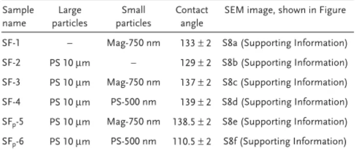
We then moved to investigate the performance of substrates with a higher packing density of polystyrene beads. In this case, the substrates have an ordered structure due to a colloidal crys-talline arrangement of the particles. The measured apparent water contact angles show values in the range of 125°–140°. Increasing the levels of roughness shows an increase in the final contact angles, as expected. Binary colloidal crystals (BCCs)-coated surfaces have a higher hydrophobicity than that of single colloidal crystals (SCCs)-coated surfaces. The different BCCs surfaces, within our experimental error, do not pre-sent significant differences, with respect to the large particles being covered or not by the smaller particles. All contact angle values fall in the range of 137° ± 3. This finding suggests that the BCCs and SCCs surfaces with contact angle values in the range of 125°–140° offer a good base for a bottom-up design of superhydrophobic surfaces, even better than that of the surface with the low density of colloidal beads, shown in Figure 6f. We therefore selected the surface made of 750 nm magnetic parti-cles and 10 μm polystyrene micropartiparti-cles, with NS/L equal to 500, as one of the BCCs providing the best results.
To reproduce the epicuticular structure of lotus,[33] the selected BCCs surface patterns were combined with silica nanofibers. We then performed the deposition of the fibrils on the BCCs surface, using LbL approach. We dipped the substrate first in a solution of positively charged silica nanoparticles of 20 nm, and then in a solution of negatively charged silica nanofibers. After one dipping cycle, the surface was not com-pletely covered by fibrils (as shown in Figure S10, Supporting Information). After three LbL deposition cycles, alternating 20 nm positively charged silica nanoparticles and negatively charged silica fibers, we obtained the complete coverage of the BCCs, as it can be seen in Figure 7. The substrate, completely coated with the silica nanofibers, was functionalized with a silane bearing an alkyl chain, DTS, by dipping the surface in a DTS/NH3/butanol solution. The contact angle of the final sub-strate, with the two level of roughness, has been measured and found to be equal to 165.5°, as shown in Figure 7e. With the presented four steps approach we prepared a complex structure inspired by the lotus leaf with superhydrophobic characteris-tics. The final WCA is comparable, and possibly even higher than that of the natural lotus leaf (which corresponding WCA values are somehow difficult to measure, and a range of values are reported in literature[34]), suggesting that the proposed approach can be used to further enhance the final superhydro-phobicity of the surface.
3. Conclusions
In this work, we have elaborated a simple and versatile approach to synthesize silica fibrils/nanotubes by condensa-tion of either TMOS or TEOS, on the surface of amyloid fibers. First, the hydrolysis–condensation of TMOS in aqueous acidic environment has been investigated. In this case, very thin silica layer, in the range of few nanometers, has been formed on the amyloid fibrils and has been characterized via AFM and TEM. The TMOS condenses not only heterogeneously on the sur-face of the fibrils but also homogeneously in the water. There-fore, even by increasing the amount of silica precursor only a thin silica layer is formed on the surface of the fibrils, and the formation of small colloidal silica particles has been observed. In the second case, TEOS has been used as silica precursor and the reaction has been performed using Stöber method. With this second approach the hydrolysis and condensation of the silica precursor occurred faster. The TEOS preferentially condenses on the surface of the fibrils forming silica layers of tunable thickness, depending on the amount of TEOS in the system, and the final fibrils produced have a diameter in the range 60–250 nm.
Secondary nucleation of TEOS, forming spherical nanoparti-cles, has been observed in some of the investigated condition. This phenomenon has been reduced by a semibatch feeding of the reagents in the system, or by decreasing the amount of ammonia used to catalyze the decomposition of TEOS. With the semibatch approach, the overall length of the fibrils is maintained, and for the highest concentration of silica pre-cursor a very smooth layer of silica has been formed. However, long fibrils still coexist together with spherical nanoparticles. By decreasing the amount of ammonia, on the other hand, the
formation of spherical nanoparticles is considerably reduced, but the silica layer formed on fibrils is quite rough.
Once prepared, these fibrils are very stable, and can offer a large surface area for further functionalization. As an example, silica-coated fibrils were chemically hydrophobized
by condensing DTS on their surface. Two kinds of synthe-sized fibrils were modified: the first one characterized by a larger diameter and smoother surface, while the second one by a thinner a very rough surface. The functionalized fibrils have then been deposited on a surface, and the contact angles
Figure 6. SEM images of SCCs and BCCs substrates at two different magnifications and the relative water contact angles. a) SCCs of 10 μm PS particles, Sub-1; b) SCCs of 750 nm magnetic particles, Sub-2; c) BCCs of 10 μm PS particles and 750 nm magnetic particles coated with 20 nm silica particles, Sub-3; d) BCCs of 10 μm and 500 nm PS particles Sub-4; e) BCCs of 10 μm PS particles and 750 nm magnetic particles, Sub-5; f) BCCs of 10 μm and 500 nm PS, low coverage, Sub-6; reported in Table 3.
of water droplets deposited on these surfaces have been meas-ured. From the contact angle measurements, it was clear that the fibrils have been successfully functionalized by DTS, since both were initially very hydrophilic and after functionalization both turned hydrophobic. In the two cases, there was a strong difference in terms of hydrophobicity. A higher water repel-lency for the fibrils characterized by the rough surface has been observed. The rough fibrils functionalized with DTS clearly showed superhydrophobicity, with a water contact angle of around 160°.
In the second part of the study, the fabrication of superhy-drophobic surfaces inspired by the lotus leaf has been shown. The surfaces have been engineered by a combination of single or binary colloidal crystals, with the objective to mimic the large-scale papillary structure of the lotus leaf, and of hydropho-bized silica nanotubes to mimic the epicuticular wax tubular structure of the leaf. The preparation of the surface consists of three main steps. First, the preparation of particles substrates has been carried out by using both single and binary colloidal crystal made of 10 μm polystyrene particles. The spacing among the particles has been controlled by using smaller sub-micrometer particles, either simple polystyrene colloids, or magnetic colloids, to generate structures with a wide range of micrometer roughness patterns. The different surfaces, coated with a 20 nm thin layer of gold, show that the roughness of the surfaces, given by the nanoparticles colloidal crystals, provides water contact angles in the range of 125°–140°, with a value that is more than double compared to that of flat surface. The con-tact angles of SCCs and BCCs are higher than the one of a lotus leaf deprived of the wax nanotubes. The latter is comparable in terms of WCA to a surface prepared with a low density of particles, like that of papillae on the surface of a lotus leaf. The best binary colloidal crystal structures have then been coated with silica nanotubes using a layer-by-layer process, alternating them with positively charged silica nanoparticles. The nano-tubes deposited on the surface have finally been functionalized
with alkyl chains to render them chemically hydrophobic. The surface completely covered with fibrils via layer-by-layer deposi-tion gives a final contact angle of 165.5°, showing superhydro-phobicity properties at least equal—or even superior—to that of the original lotus leaf. The proposed approach is very simple and can be easily scaled up, without requiring any expensive lithographic method.
4. Experimental Section
Materials: β-Lactoglobulin from bovine milk, lyophilized powder, was purchased from Sigma Aldrich. TEOS (98%) and DTS were purchased from Acros Organics. Ammonium hydroxide solution (25%) was purchased from Sigma-Aldrich. EtOH (Absolute Reagent) was purchased from HoneyWell. TMOS was purchased from Fluka. Throughout the study, either Milli-Q (Millipore) water or distilled water stripped with nitrogen (for at least 40 min) were used. Monodisperse micro and sub-micrometer polystyrene colloids, with a size of 10 μm and 0.5 μm, respectively, were purchased from Sigma Aldrich. AllMag PM3-050 superparamagnetic polymer nanoparticles, with a size of 0.75 μm, were purchased from Allrun Nano, Shanghai, China. Silica nanoparticles with a diameter of 20 nm, positively charged (Ludox CL), with a weight fraction of 30% were purchased from Sigma Aldrich. DTS was purchased from Gelest.
Preparation of Amyloid Fibrils: Stock solutions of β-lactoglobulin at a concentration of 10 wt% in Milli-Q water were prepared by shaking the protein solution at room temperature for half an hour and were then filtered through a 0.2 μm syringe filter to remove the nondissolved material. Protein fibers were prepared by incubating β-lactoglobulin in HCl solution at 80 °C and pH 2.0 with a protein concentration of 10 mg mL−1 for 12 h in 30 mL snap-claps glass vials (supplied by VWR).
Fibril formation from β-lactoglobulin was confirmed and characterized using AFM, TEM, and zeta potential measurements. A typical AFM picture of β-lactoglobulin fibrils is shown in Figure S1 (Supporting Information).
Silica Coating of Amyloid Fibrils: Hydrolysis–Condensation of TMOS in Aqueous Acidic Environment: Silica growth on amyloid fibrils was
performed under aqueous acidic conditions using TMOS as silica precursor. In a typical procedure, 1 mL of the original solution of
Figure 7. SEM images of the BCCs surface (Sub-5, Table 3), coated with silica nanofibers via LbL deposition, at different magnifications, as indicated
by the scale bars: a) 10 μm, b) 5 μm, c) 2 μm, d) 1 μm; and e) the corresponding water contact angle (165.5 ± 2°).
protein fibril (at a concentration of 10 g L−1 and a pH = 2.0) was diluted
ten times by adding 9 mL of water, to reach a final pH = 3.0. Then, a defined amount of TMOS was then added to the system, depending on the targeted thickness of the silica layer (the amounts are reported in Table 1), dissolved by ultrasonication (using a Hielsher UP 400S horn sonicator for a duration of 6 min, with cycles of 0.5 s, and 60% of the maximum amplitude) and left reacting under strong magnetic mixing (250 rpm) for 4 h. The fibrils were then separated from the excess of TMOS through five centrifugation–redispersion cycles. The final fibrils were then analyzed via atomic force microscopy and transmission electron microscopy.
Silica Coating of Amyloid Fibrils: Hydrolysis–Condensation of TEOS under Stöber Conditions: Silica condensation with amyloid fibrils was
also performed under Stöber conditions in EtOH/water mixtures using ammonia as catalyst and TEOS as silica precursor. Several different parameters affecting the thickness and roughness of the final fibrils were varied: the concentration of silica precursor, the concentration of catalyst (ammonia), the feeding process (batch or semibatch), and the overall concentration of amyloid fibrils in the system. All the operating conditions are reported in Table 1. In a typical procedure, used for samples SF-1, SF-2, SF-3, and SF-4, 1 mL of β-lactoglobulin fibril solution at the concentration of 10 mg mL−1 was added to 9 mL
of ethanol solution. Different aliquots, reported in Table 2, of a mixture at 1/1 volume ratio of TEOS/ammonia aqueous solutions (the latter at 25 w%) were added dropwise and let to react 24 h at room temperature under magnetic stirring at 250 rpm, resulting in silica-coated fibrils with tunable thickness. In samples SFp-5, SFp-6, and SFp-7 (see Table 2),
the same conditions were used as in samples SF-4, SF-3, and SF-1, respectively, but with a semibatch feeding of the TEOS in the system. To minimize secondary nucleation of silica nanoparticle during the condensation reaction, TEOS was mixed with a portion of the EtOH (5 mL) and added to the fibrils/ammonia/ethanol mixture with a syringe pump, at a flow rate of 0.5 mL h−1. In sample SF
p-8, the overall effect
of the concentration of fibrils was varied, as well as that of TEOS/ ammonia. Compared to sample SF_4, only 100 μL of fibrils was added to 9 mL of ethanol, and the amount of TEOS/ammonia mixture added was only 100 μL. Finally, as reported in Table 1, for samples SFp-9, SFp-10,
and SFp-11, 1 mL of β-lactoglobulin fibril solution at the concentration
of 10 mg mL−1 was added to 9 mL of ethanol solution, but the ratio of
TEOS/ammonia solution added was varied, as reported in Table 2.
Silica Nanofibers Functionalization: To chemically hydrophobize the
surface of silica-modified fibrils, these were further functionalized by grafting DTS, under Stöber conditions. All silica-coated fibrils prepared in a single batch, as described in the previous section (in the case of sample SFp-5 and SFp-10 in Table 2) were purified by means of three
centrifugation (15 min at 30 000G, Beckmann Coulter Centrifuge Avanti J-26 XP) and redispersion (20 min ultrasonication, 0.5 s cycles, 60% amplitude) cycles, and finally transferred into 9 mL of 1-butanol. 1 mL of Milli-Q water and 1 mL of NH3 (25%) were then added. Under strong
magnetic stirring (250 rpm) 100 μL of DTS was finally added to the system. The mixture was stirred at room temperature for 24 h and the final dispersion was washed five times with 1-butanol.
Preparation of the Polymeric Patterned Surfaces: SCCs and BCCs films
were prepared on a silicon substrate (chosen for imaging purposes). The physical dimensions of the substrates were 0.5 cm2, and after deposition
of the particle suspensions the entire substrate surface was covered. Well-ordered single colloidal crystals of 10 μm particles were prepared by depositing on a silicon substrate 3 μL of particles suspension at 10 wt% (Sub-2, Table 3). Multilayer magnetic particles substrates, 750 nm in size, were created by depositing on a silica substrate 30 μL of particle suspension 4% in weight (Sub-1, Table 3). Well-ordered BCCs (of 10 μm and 500 nm), in which the 500 nm nanoparticles positioned themselves around and on top of the 10 μm particles, were fabricated based on an improved self-assembly method. PS aqueous colloidal suspensions of both populations of particles were mixed together in a vial. The final colloidal suspension was then deposited on the substrate. The solvent was evaporated slowly over a period of 10 h under sonication using a sonication bath. The number ratio of small to large colloidal spheres,
denoted as NS/L, and the particles size ratio were varied producing a
variety of different patterns (Sub-4).
For the preparation of well-ordered BCCs (of 10 μm and 750 nm magnetic nanoparticles), in which the smaller particles deposit only around and not on top of the bigger one, the drying process was carried under a magnetic field. The binary mixture of particles was deposited on top of the silica surface and placed under a customized plastic support, on top of which a small magnet (disc magnets, 10 mm × 5 mm) was attached, parallel to the sample (Sub-5, Table 3).
BCCs surfaces of polymer particles covered with 20 nm silica nanoparticles were prepared via LbL deposition. The Sub-5 sample was dipped in a solution (at 10 wt%) of positively charged silica nanoparticles (Ludox CL), and subsequently washed with 1 mL Milli-Q water (Sub-3, Table 3). Then several LbL deposition cycles with negatively charged silica nanofibers and positively charged silica nanoparticles were performed in order to obtain the final desired superhydrophobic surfaces.
All the substrates were coated before imaging with SEM with a 20-nm-thick gold film, using an Au-target (Sputter Target, Au, Gold, 57 × 0.2 mm, from Elektronen-Optik-Service GmbH, Dortmund, Germany) by means of a Cressington-Sputter-Target. The samples not covered with silica nanoparticles and with silica nanofibers were also coated with a 20-nm-thick gold film before WCA measurements. In Table 3, the compositions of all substrates fabricated in this study are reported.
Characterizations: AFM images were collected with a JPK NanoWizard
II device. All images shown in this work were obtained in height mode. TEM images were acquired with a FEI Tecnai Spirit microscope, while SEM images were acquired with a TESCAN Mira 3 LM field emission microscope. Zeta potential measurements were performed with a Brookhaven Instrument 90 Plus particle size analyzer.
Supporting Information
Supporting Information is available from the Wiley Online Library or from the author.
Acknowledgements
The authors would like to acknowledge financial support from the Swiss National Science Foundation (Grant No. PP00P2126483/1), the National Center of Competence for Research “bioinspired materials,” and the Adolphe Merkle Foundation.
Conflict of Interest
The authors declare no conflict of interest.
Table 3. Compositions of BCCs and SCCs substrates made with large
and small particles, and their relative contact angles measurements after coating them with gold.
Sample name Large particles Small particles Contact angle
SEM image, shown in Figure
SF-1 – Mag-750 nm 133 ± 2 S8a (Supporting Information) SF-2 PS 10 μm – 129 ± 2 S8b (Supporting Information) SF-3 PS 10 μm Mag-750 nm 137 ± 2 S8c (Supporting Information) SF-4 PS 10 μm PS-500 nm 139 ± 2 S8d (Supporting Information) SFp-5 PS 10 μm Mag-750 nm 138.5 ± 2 S8e (Supporting Information)
SFp-6 PS 10 μm PS-500 nm 110.5 ± 2 S8f (Supporting Information)
Keywords
amyloid fibrils, binary colloidal crystals, layer-by-layer deposition, silica nanotubes, superhydrophobic surfaces
[1] a) J.-T. Sun, C.-Y. Hong, C.-Y. Pan, J. Phys. Chem. C 2010, 114, 12481; b) S. B. Lee, D. T. Mitchell, L. Trofin, T. K. Nevanen, H. Söderlund, C. R. Martin, Science 2002, 296, 2198; c) C. R. Martin, P. Kohli, Nat.
Rev. Drug Discovery 2003, 2, 29; d) Y. Xia, P. Yang, Y. Sun, Y. Wu,
B. Mayers, B. Gates, Y. Yin, F. Kim, H. Yan, Adv. Mater. 2003, 15, 353; e) W. Liu, Z. Zhu, K. Deng, Z. Li, Y. Zhou, H. Qiu, Y. Gao, S. Che, Z. Tang, J. Am. Chem. Soc. 2013, 135, 9659.
[2] H. Nakamura, Y. Matsui, J. Am. Chem. Soc. 1995, 117, 2651. [3] a) S.-S. Choi, S. G. Lee, S. S. Im, S. H. Kim, Y. L. Joo, J. Mater. Sci.
Lett. 2003, 22, 891; b) N. I. Kovtyukhova, T. E. Mallouk, T. S. Mayer, Adv. Mater. 2003, 15, 780.
[4] a) H.-P. Lin, C.-Y. Mou, S.-B. Liu, Adv. Mater. 2000, 12, 103; b) Y. Tang, L. Pei, Y. Chen, C. Guo, Phys. Rev. Lett. 2005, 95, 116102. [5] a) J. Jang, H. Yoon, Adv. Mater. 2004, 16, 799; b) M. Harada,
M. Adachi, Adv. Mater. 2000, 12, 839.
[6] a) C. R. Martin, DTIC Document, 1994; b) C. R. Martin, Chem.
Mater. 1996, 8, 1739.
[7] B. He, S. J. Son, S. B. Lee, Anal. Chem. 2007, 79, 5257.
[8] a) M. Kim, J. Hong, J. Lee, C. K. Hong, S. E. Shim, J. Colloid
Inter-face Sci. 2008, 322, 321; b) T.-W. Lin, H.-H. Shen, Nanotechnology
2010, 21, 365604.
[9] J. Zhu, H. Peng, S. T. Connor, Y. Cui, Small 2009, 5, 437.
[10] R. Fan, Y. Wu, D. Li, M. Yue, A. Majumdar, P. Yang, J. Am. Chem.
Soc. 2003, 125, 5254.
[11] Y. Chen, X. Xue, T. Wang, Nanotechnology 2005, 16, 1978. [12] K.-W. Hu, K.-C. Hsu, C.-S. Yeh, Biomaterials 2010, 31, 6843. [13] S. O. Obare, N. R. Jana, C. J. Murphy, Nano Lett. 2001, 1, 601. [14] a) S. Banerjee, A. Datta, Langmuir 2010, 26, 1172; b) T. Fukamachi,
T. Endo, Y. Yabuki, T. Ogura, T. Misono, K. Torigoe, K. Sakai, M. Abe, H. Sakai, J. Oleo Sci. 2015, 64, 663; c) D. Xu, Z. Huang, R. Miao, Y. Bie, J. Yang, Y. Yao, S. Che, J. Mater. Chem. A 2014, 2, 19855. [15] J. Yang, W. Chen, X. Ran, W. Wang, J. Fan, W.-x. Zhang, RSC Adv.
2014, 4, 20069.
[16] a) W.-J. Zhang, C.-Y. Hong, C.-Y. Pan, J. Mater. Chem. A 2014, 2, 7819; b) M. Zhang, W. Zhang, S. Wang, J. Phys. Chem. C 2010,
114, 15640; c) J. M. Zhao, W. Huang, P. C. Si, J. Ulstrup, F. Y. Diao,
J. D. Zhang, Macromol. Rapid Commun. 2018, 39, 1870028; d) M. Mandal, G. Farid, M. Kruk, J. Colloid Interface Sci. 2018, 524, 445. [17] a) M. Yamanaka, Y. Miyake, S. Akita, K. Nakano, Chem. Mater. 2008,
20, 2072; b) C. Lin, Y. Song, F. Gao, H. Zhang, Y. Sheng, K. Zheng,
Z. Shi, X. Xu, H. Zou, J. Sol-Gel Sci. Technol. 2014, 69, 536.
[18] X. Wan, X. Pei, H. Zhao, Y. Chen, Y. Guo, B. Li, K. Hanabusa, Y. Yang, Nanotechnology 2008, 19, 315602.
[19] Y. Okazaki, J. Cheng, D. Dedovets, G. Kemper, M.-H. Delville, M.-C. Durrieu, H. Ihara, M. Takafuji, E. Pouget, R. Oda, ACS Nano
2014, 8, 6863.
[20] a) W. Liu, K. Alim, A. Balandin, D. Mathews, J. Dodds, Appl.
Phys. Lett. 2005, 86, 253108; b) E. Royston, S.-Y. Lee, J. N. Culver,
M. T. Harris, J. Colloid Interface Sci. 2006, 298, 706.
[21] a) R. Fan, R. Karnik, M. Yue, D. Li, A. Majumdar, P. Yang, Nano
Lett. 2005, 5, 1633; b) S. J. Son, X. Bai, A. Nan, H. Ghandehari,
S. B. Lee, J. Controlled Release 2006, 114, 143; c) H. Hillebrenner, F. Buyukserin, M. Kang, M. O. Mota, J. D. Stewart, C. R. Martin,
J. Am. Chem. Soc. 2006, 128, 4236.
[22] Q. Ji, S. Kamiya, J.-H. Jung, T. Shimizu, J. Mater. Chem. 2005, 15, 743.
[23] a) S. Wang, Q. Cai, M. Du, J. Xue, H. Xu, J. Phys. Chem. B 2015; b) S. Wang, J. Xue, Y. Zhao, M. Du, L. Deng, H. Xu, J. R. Lu, Soft
Matter 2014, 10, 7623; c) B. Liu, Y. Cao, Z. Huang, Y. Duan, S. Che, Adv. Mater. 2015, 27, 479; d) S. Ahmed, J. H. Mondal, N. Behera,
D. Das, Langmuir 2013, 29, 14274; e) H. Choi, J. J. Kim, Y. H. Mo, B. M. Reddy, S. E. Park, Langmuir 2017, 33, 10707; f) I. W. Song, H. Park, J. H. Park, H. Kim, S. H. Kim, S. Yi, J. Jaworski, B. I. Sang,
Sci. Rep. 2017, 7, 16212; g) S. Xu, Y. F. Wang, W. Qi, R. X. Su,
Z. M. He, ChemistrySelect 2018, 3, 4939;
[24] J. E. Meegan, A. Aggeli, N. Boden, R. Brydson, A. P. Brown, L. Carrick, A. R. Brough, A. Hussain, R. J. Ansell, Adv. Funct. Mater.
2004, 14, 31.
[25] Z. S. Al-Garawi, J. R. Thorpe, L. C. Serpell, Angew. Chem., Int. Ed.
2015, 54, 13327.
[26] a) C. Li, J. Adamcik, R. Mezzenga, Nat. Nanotechnol. 2012, 7, 421; b) C. Li, S. Bolisetty, R. Mezzenga, Adv. Mater. 2013, 25, 3694; c) C. Li, A. K. Born, T. Schweizer, M. Zenobi-Wong, M. Cerruti, R. Mezzenga, Adv. Mater. 2014, 26, 3207; d) S. Bolisetty, J. J. Vallooran, J. Adamcik, R. Mezzenga, ACS Nano 2013, 7, 6146; e) S. Bolisetty, R. Mezzenga, Nat. Nanotechnol. 2016, 11, 365. [27] J. Wang, H. Chen, T. Sui, A. Li, D. Chen, Plant Sci. 2009, 176, 687. [28] H. J. Ensikat, P. Ditsche-Kuru, C. Neinhuis, W. Barthlott, Beilstein J.
Nanotechnol. 2011, 2, 152.
[29] a) N. A. Patankar, Langmuir 2003, 19, 1249; b) B. Bhushan, E. K. Her, Langmuir 2010, 26, 8207.
[30] a) T. Limongi, F. Cesca, F. Gentile, R. Marotta, R. Ruffilli, A. Barberis, M. Dal Maschio, E. M. Petrini, S. Santoriello, F. Benfenati, E. Di Fabrizio, Small 2013, 9, 402; b) A. Accardo, E. Di Fabrizio, T. Limongi, G. Marinaro, C. Riekel, J. Synchrotron Radiat.
2014, 21, 643; c) G. Marinaro, A. Accardo, F. De Angelis, T. Dane,
B. Weinhausen, M. Burghammer, C. Riekel, Lab Chip 2014, 14, 3705; d) L. Ye, J. Guan, Z. Li, J. Zhao, C. Ye, J. You, Y. Li, Langmuir
2017, 33, 1368.
[31] P. Zhang, F. Lv, Energy 2015, 82, 1068.
[32] M. Nosonovsky, B. Bhushan, Microelectron. Eng. 2007, 84, 382. [33] L. Gao, T. J. McCarthy, Langmuir 2006, 22, 2966.
[34] C. W. Extrand, S. I. Moon, Langmuir 2014, 30, 8791.